

RAY
RESIDENTIAL GATE OPERATOR
& CONTROLLER
USER MANUAL
Gear Motor for Hinged Gates
v.5.1.17
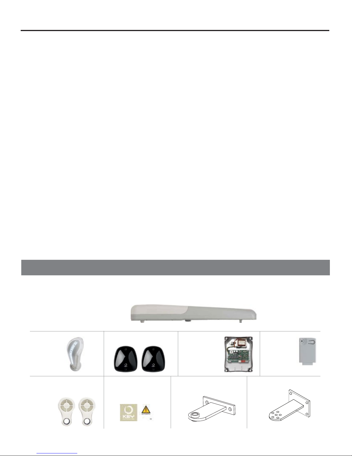
TABLE OF CONTENTS
GATE ARM
Product Overview........................................................1
Preliminary Checks.......................................................1
Quick Start Installation.....................................................2
Installation Guideline......................................................4
Testing and Commissioning the Automation....................................8
Safety Warnings.........................................................9
Instructions and Warnings for the End User....................................10
CONTROLLER
About the Controller......................................................12
Technical Specifications..................................................13
Preliminary Checks................................... ...................13
Installing the Controller...................................................14
Quick Programmming Guide...............................................16
Full Programmming Guide.................................................19
Testing and Commissioning the Automation..................................25
Further Details..........................................................26
Controller Safety Warnings................................................30
Instructions and Warnings for the End User....................................31
WHAT’S IN THE BOX
Before proceeding with the installation, check the integrity of the product and that all the components are present in
the package.
RAY GATE OPERATOR
(1) for SINGLE SWING GATE OR
(2) for DOUBLE SWING GATE
(1) ECLIPSE
LIGHT
(1) FT32 PHOTOCELL
(1) 14A
CONTROLLER
(1) RX4X
RECEIVER
(2) CHAMELEON
TRANSMITTERS
(1) STICKER WITH
WARNING TAG
(1) FRONT MOUNTING
BRACKET
(1) REAR MOUNTING
BRACKET
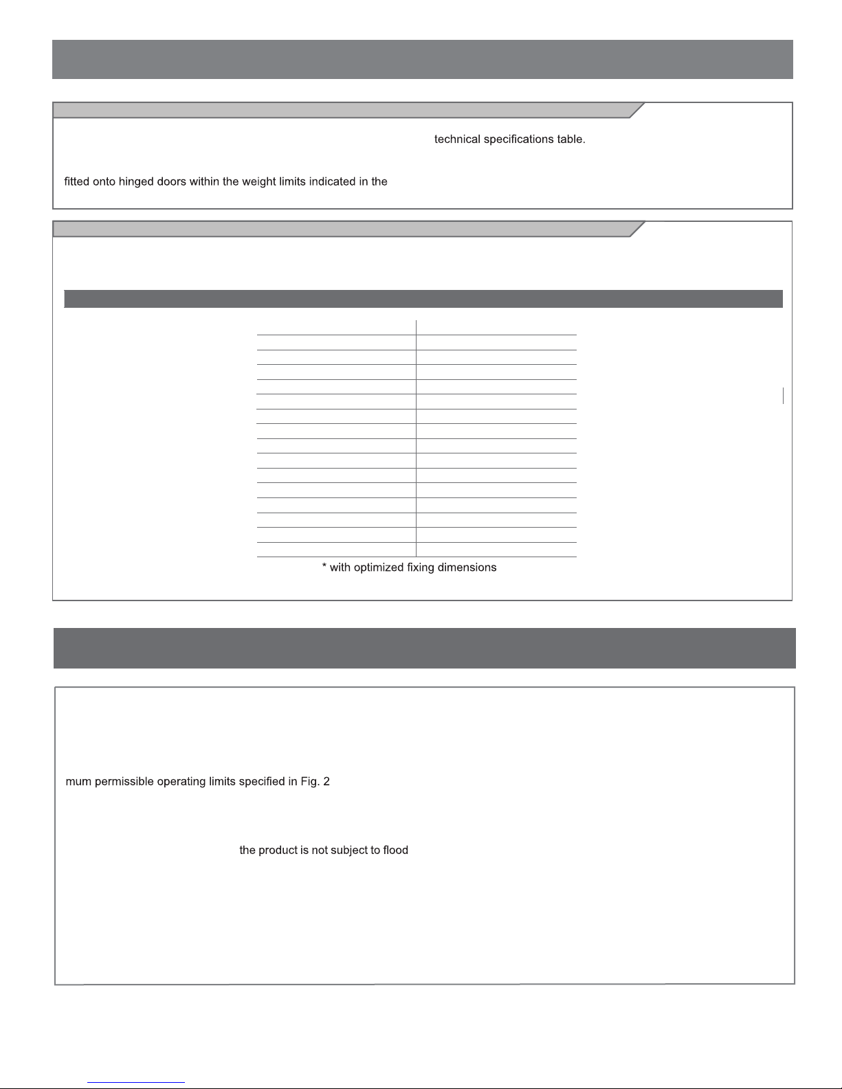
PRODUCT OVERVIEW
Description of the product
The RAY gear motors are destined to be installed in systems for the
automation of gates with hinged doors.
The RAY gear motors have been designed and constructed to be
Model and technical characteristics
RAY4024E: Gear motor for hinged gate with max length of 13 feet and 500 lbs or 6 1/2 feet and 1320 lbs.
(Refer to chart in Fig 2 for limit use.)
TECHNICAL SPECIFICATIONS
Thrust force 2000 N
Working cycle 80%
Opening time at 90° (sec) 20-25*
Working stroke 415 mm
Control board 14AB2
Primary Power 110 Vac
Secondary Power 24 Vdc
Absorption 5 A
Engine power 120 W
Integrated lights yes
Degree of protection NEMA 3R (IP44)
Dimensions (L - P - H) 33 7/32” x 3 15/16” x 4 3/32”
Weight 18 lbs
Operating temperature -4°to 133°F
Leaves maximum weight 1320 lbs
The use of gear motors for applications which differ from those
indicated above is prohibited.
RAY4024E
PRELIMINARY CHECKS
Before installing this product, verify and check the following steps:
- Check that the gate or door are suitable for automation
- The weight and size of the gate or door must be within the maxi-
- Check the presence and strength of the security mechanical stops
of the gate or door
- Check that the mounting area of
ing
- Conditions of high acidity or salinity or proximity to heat sources
could cause malfunction of the product
- Extreme weather conditions (for example the presence of snow,
ice, high temperature range, high temperatures) may increase the
friction and therefore the force required for the handling and initial
starting point may be higher than under normal conditions.
- Check that the manual operation of gate or door is smooth and
friction-free and there is no risk of derailment of the same
- Check that the gate or door are in equilibrium and stationary if left
in any position
- Check that the power line to supply the product is equipped with
proper grounding safety and protected by a magnetothermal and
differential security device
-
- Provide the power system with a disconnecting device with a gap
of contacts enabling full disconnection under the conditions dictated
by the overvoltage category III.
- Ensure that all materials used for the installation comply with current regulations
1
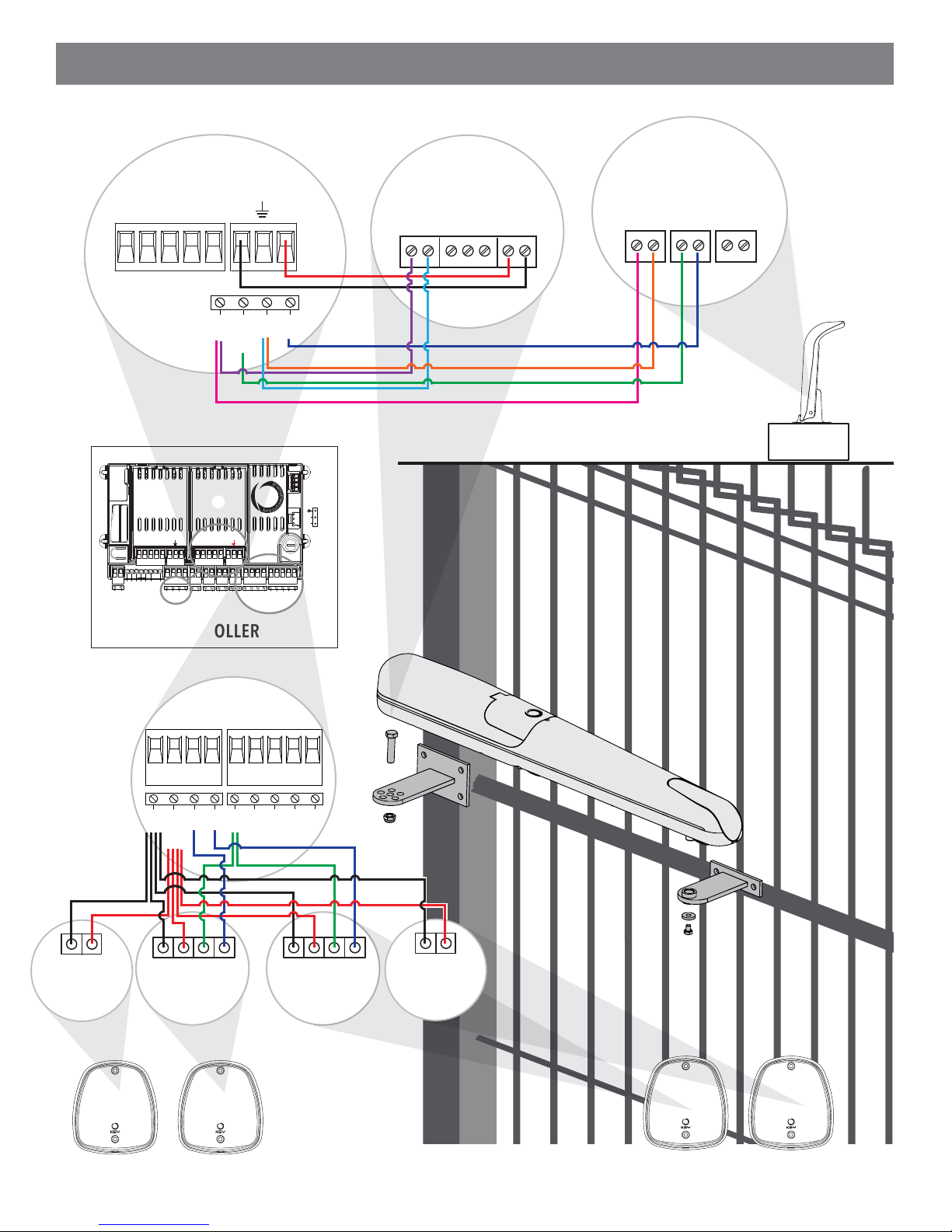
QUICK START INSTALLATION
CONTROLLER
WARNING LIGHT
GATE ARM
CS1
CS2
V+ENC
NEG
COM
M-M
LED
FLASH
+
SEN
COM
LED
NEG
-
M+
M
COM
LED
FLASH
SENSOR
+
V
ENC
WARNING
LIGHT
M2
CS1
CS2
V+ENC
SBS
SHIELD
NEG
PH1
PH2
PED
SBS
STOP
EDGE
OPEN
CLOSE
ANT
M-M+LS1
LED
COM
FLASH
M1
+
LS2
V+ENC
NEG
M-M
IND
SEN
COM
COM
PH1
PH2
NEG
COM
ELEC
STOP
EDGE
EDGE
PH-POW
BATTERIES
(ACCESSORY)
POWER
SUPPLY
PED
SBS
COM
OPEN
CLOSE
CONTROLLER
-
12/24
GND
AC/DC
PHOTO EYE
1 TX
TX
CONTROLLER
PH1
NEG
PH-POW
-
12/24
GND
AC/DC
PHOTO EYE
1 RX
COM
RX
PH2
OUT
COM
PED
OPEN
CLOSE
-
GND
PHOTO EYE
SBS
12/24
AC/DC
2 RX
COM
OUT
-
12/24
GND
AC/DC
PHOTO EYE
2 TX
RX
TX
PHOTO EYE 1
2
PHOTO EYE 2
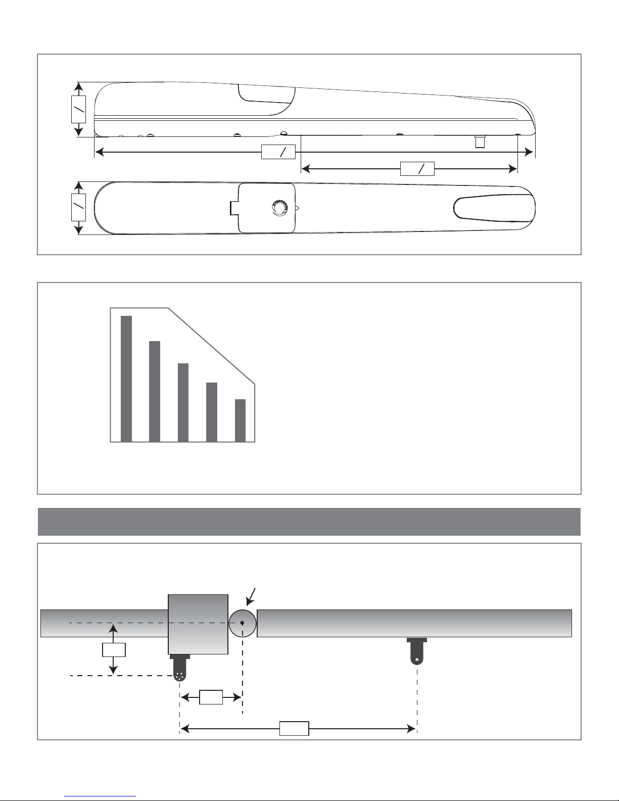
SPACE DIMENSIONS
Ensure that the mounting area of the gear motor is compatible with the dimensions in Fig 1.
”
32
3
4
”
16
15
3
USE LIMITATIONS
7
33
”
32
11
”
16
32
Fig. 1
LIMIT USE
1320
1100
880
660
440
MAX GATE WEIGHT (lbs)
220
MAXIMUM GATE LENGTH (ft)
OPTIMAL INSTALLATION
OUTSIDE
PROPERTY
Steel Square
Tubing
Ensure that the gate weight and length is compatible with
the table in Fig 2.
LBS
Maximum weight of the gate
FT
Maximum length of the gate
1311.51086.5
Gate Rotation Center (Hinge)
Gate Closed
Fig. 2
Fig. 3
6¾”
6¾”
GATE
INSIDE
PROPERTY
29½”
3
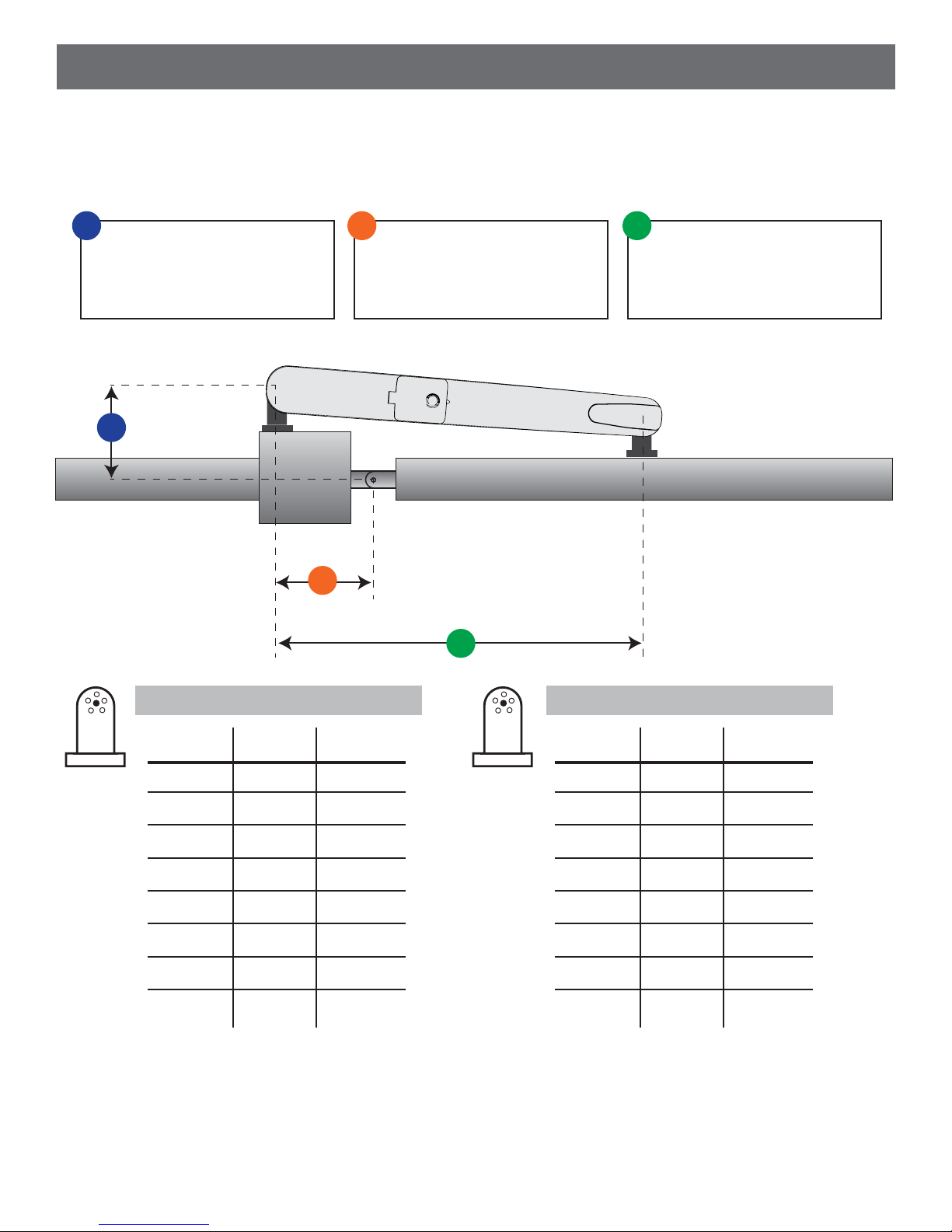
INSTALLATION GUIDELINE
1. Measure the distance “A” from the center point of the hinge to the rear bracket hole.
2. Use the table to determine the optimum measurement for “B” and attach the rear bracket to the post.
3. Mount the front bracket so that the hole of the front bracket is 29 1/2” from the hole on the rear bracket “C”.
A
Measurement between the
center of the gate plane and
the rear bracket hole
A
B
B
Measurement between the
center of the gate hinge and
the rear bracket hole plane
C
C
Measurement between the
front and rear brackets
Fig. 4
90°-100° OPENING
A (in)
4”
4 1/4”
4 1/2”
4 3/4”
7”
7 1/4”
7 1/2”
7 3/4”
Check the permitted opening angle based on the mounting points of the brackets in the charts in Fig 4.
B (in)
4”
4 1/4”
4 1/2”
4 3/4”
7”
7 1/4”
7 1/2”
7 3/4”
C (in)
29 1/2”
29 1/2”
29 1/2”
29 1/2”
29 1/2”
29 1/2”
29 1/2”
29 1/2”
100°-110° OPENING
A (in)
5”
5 1/4”
5 1/2”
5 3/4”
6”
6 1/4”
6 1/2”
6 3/4”
B (in)
5”
5 1/4”
5 1/2”
5 3/4”
6”
6 1/4”
6 1/2”
6 3/4”
29 1/2”
29 1/2”
29 1/2”
29 1/2”
29 1/2”
29 1/2”
29 1/2”
29 1/2”
C (in)
4
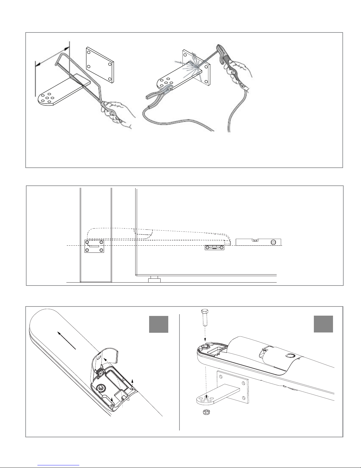
CUTTING & INSTALLING THE REAR BRACKET
The fixing position
of the rear bracket
is determined
according to the
graphic and measurement table
listed in Fig 4.
IMPORTANT:
Optimal installations occur when the values of “A” and “B” are as close to each other as possible.*
If necessary, cut the rear bracket then weld the bracket to the post as shown in Fig 5.
ATTACHING THE FRONT BRACKET
Fig. 5
The front bracket must be fixed to the door according to the dimension “C” in Fig 4. The front bracket
must be fixed at the same height as the rear bracket
as shown in Fig 6.
SECURING THE GEAR MOTOR AND REAR BRACKET
Fig. 7
3
1
a
2
Fig. 6
b
Open the
release door and
remove the 2 screws
that secure the rear
cover as shown in Fig. 7a. Next, remove the top
cover by sliding it slightly backwards.
2
2
Place the gear motor against the bracket and insert
the fixing screw as shown in Fig. 7b.
5
1
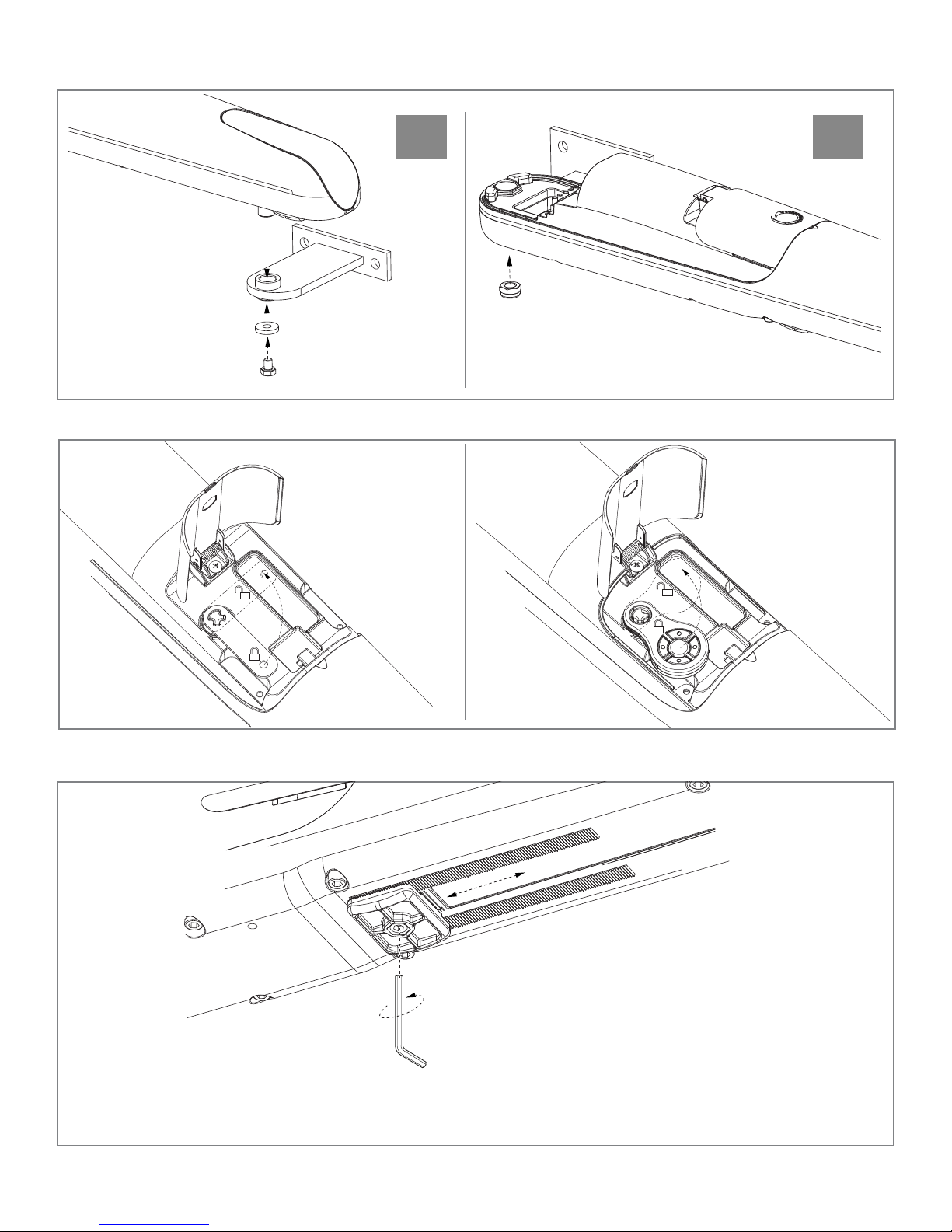
SECURING THE GEAR MOTOR AND REAR BRACKET (continued)
c d
Fig. 7
Insert the pin of
the sliding bracket
into the bushing of
the front bracket and
secure it with the
screw and washer
as shown in Fig. 7c.
GEARMOTOR RELEASE
1
2
3
Fig. 8
Release the gear
motor as shown
in Fig. 8.
Tighten the screw on the
rear bracket previously mounted
with the nut as shown in Fig 7d.
SETTING OF THE MECHANICAL LIMIT SWITCH
Fig. 9
Loosen the screw on the mechanical limit switch until
it is able to slide. Open the gate manually to the
desired opening position. Bring the mechanical limit
switch up to the pin of the slide bracket and secure it
with the screw as shown in Fig. 9. If you need to
adjust the mechanical limit switch for the closing
position repeat the same procedure, this time manually bringing the gate to the desired point of closure.
6
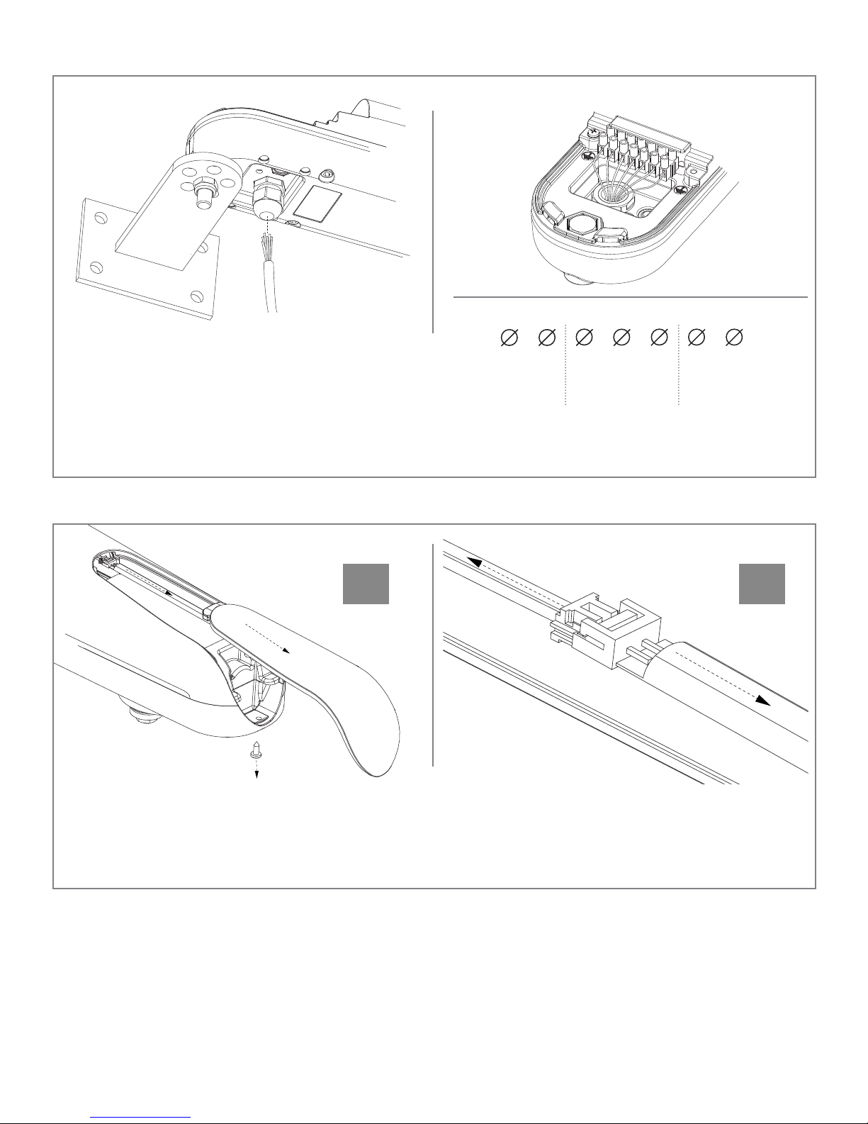
POWER CONNECTIONS
LED
ENC
NEG
Loosen the cable and insert the power cord as
shown in Fig. 10. Connect the wires of the power
cable to the terminal block according to the wiring
diagram in Fig. 10. Screw the cable gland tight to
secure the wires. Replace the top cover - first sliding
it slightly backward, open the door and tighten the 2
screws that secure the rear cover.
24 Vdc
RAY4024E
COM
LED ENCODER MOTOR
V+
M+
Fig. 10
M-
REPLACEMENT OF THE LEDS
3
Turn off the power supply. Use a screwdriver to remove the lower screw as shown in Fig. 11a. Remove
the cover and LED strip as shown in Fig. 11a. Disconnect the connector as shown in Fig. 11b. Connect
the new LEDs and insert them into the mask. Connect the mask by first inserting the side of the seal
and then securing it with the screw.
Only 24 Vdc
a
2
1
Fig. 11
b
7

TESTING AND COMMISSIONING THE AUTOMATION
cians who must perform the tests required by relevant legislation
-
related to risks, ensuring compliance with the provisions of the
5.1 Testing
All system components must be tested following the procedures
outlined in the respective instruction manuals.
Check that they meet the guidelines in Safety warnings. Check that
the gate or door can move freely once the automation is unlocked,
and that they are in equilibrium and stationary if left in any
position.
5.2 Commissioning
Following the successful testing of all (and not just some) devices in
the system you can proceed with the commissioning.
system with the wiring diagram, drawing or photo of the system,
risks analysis and solutions adopted, manufacturer declaration of
conformity of all devices connected, instruction manual of each device and maintenance schedule of the system.
Fix on the gate or door a plaque indicating the automation data, the
name of the person responsible for the commissioning, the serial
number and year of construction, the CE mark.
testing methods for the automation of doors and gates.
Check the correct operation of all connected devices (photocells,
sensitive edges, emergency buttons, etc.), testing the opening,
closing and stopping of the gate or door via the connected control
devices (transmitters, buttons, switches).
Carry out measurements of the impact force, as prescribed by
standard EN12445 adjusting the functions of speed, motor force
and deceleration of the unit if the measurements do not give the
Attach a plaque indicating the steps required to manually unlock
the system.
Implement and deliver to the end user the declaration of conformity, the instructions and warnings for use for the end user and the
maintenance schedule of the system.
Make sure the user understands proper automatic, manual and
emergency operation of the automation.
Inform the end user in writing of the dangers and risks still present.
8

SAFETY WARNINGS
WARNING - for the safety of people, it is important to
adhere to these instructions and save them for future
use.
Read the instructions carefully before starting installation.
The design and manufacture of the devices making
up the product and the information contained in this
manual comply with safety regulations. However,
wrong installation and programming may cause seri-
ous physical injury to those who perform the work
and those who will use the device. For this reason,
during installation, it is important to carefully follow
all instructions in this manual.
Do not proceed with the installation if you have doubts of any kind
By the European legislation, the creation of a door or
gate must comply with the rules laid down in Direc-
tive 2006/42/EC (Machinery Directive) and in particular, EN 12445; EN 12453; EN 12635 and EN 13241-1
standards, which allow you to declare the compliance
of the automation.
mation, the system tests, its commissioning and maintenance must
the instructions in "Testing and commissioning of the automation".
- If liquid falls into any part of the automation components, immediately disconnect the power supply and contact the Key Automation
Customer Service. The use of the automation under these condi-
tions can be dangerous;
- Do not place the various components near sources of heat and do
- All operations requiring the opening of the protective shell of vari
ous automation components, must be performed with the power unit
disconnected from the supply. If the disconnection device is not vis
ible, place a "MAINTENANCE IN PROGRESS" sign;
- The Power unit must be connected to a power supply line provided
with grounding safety;
- The product cannot be considered an effective system of protec
need to integrate the automation with other devices;
- The product can be used only after the "commissioning" of au
tomation has been made, as provided in paragraph "Testing and
commissioning of the automation";
- Provide the power system with a disconnecting device with a gap
of contacts enabling full disconnection under the conditions dictated
by the overvoltage category III;
-
-
-
-
Moreover, the personnel shall also take responsibility to establish
the tests related to the risks involved and verify compliance with
the provisions of laws, rules and regulations: in particular, compliance with all requirements of standard EN 12445, which establishes
IMPORTANT - Before starting the installation, perform
the following analysis and tests:
- Ensure that the individual automation devices are suitable for the
system to be built. In this regard, check with particular attention the
data contained in the "Technical data" section. Do not install if even
one of the devices is not suitable for use.
safety and functionality.
- Perform risk analysis, which must also include the list of essential
safety requirements set out in Annex I of the Machinery Directive,
indicating the solutions adopted. Risk analysis is one of the docu-
completed by a professional installer.
Considering the hazards that may occur during in-
stallation and use of the product you need to install
the automation observing the following precautions:
- Do not make changes to any part of the automation, other than
with IP55 degree of protection or higher;
- The electric system upstream of the automation shall comply with
current regulations and must be made in a workmanlike manner;
- It is recommended to use an emergency button to be installed near
the automation (connected to the STOP input of the control card) so
that you can immediately stop the gate or door in case of danger;
This device is not intended for use by persons (including children)
whose physical, sensory or mental abilities are reduced, or who
have lack of experience or knowledge, unless they have been able
safety, from supervision or instruction concerning use of the device.
Children should be supervised to make sure they do not play with
the device.
WARNING - The packaging material of all components must be disposed of in compliance with local
regulations.
WARNING - The data and information provided in this
manual are subject to change at any time without notice by Key Automation S.r.l.
to malfunction. The manufacturer disclaims any liability for damage
- Keep the parts of the components from being immersed in water or
other liquids. During the installation, ensure that no liquid penetrates
into the devices;
9

INSTRUCTIONS AND WARNINGS FOR THE END USER
Key Automation S.r.l. produces systems for the automation of gates,
garage doors, automatic doors, shutters, parking lots and road barriers. However, Key Automation is not the manufacturer of your automation system, which is rather the result of a process of analysis,
evaluation, selection of materials, and installation performed by
your own installer. Each automated system is unique and only your
installer has the experience and professionalism required to create
a system to suit your needs, safe and reliable over time, and carried
out in a workmanlike manner, i.e. compliant with the current regulations. Even if your automation system meets the security level required by law, this does not exclude the existence of "residual risks",
i.e. the possibility that it may cause dangerous situations, usually as
a result of improper or irresponsible use; for this reason we would
like to give you some suggestions:
explain the origin of residual risks.
• Keep this manual for future use and deliver it to any new owner of
the automation.
• Inappropriate or improper use of the automation can make it dangerous: do not command the movement of the automation if people,
animals or things are in its range.
• Children: If properly designed, an automation system ensures a
high degree of security, preventing movement in the presence of
people or things with its detection systems, and ensuring always
predictable and safe activation. It is prudent to prevent children from
playing near the automation and keep remote controls out of their
reach to prevent accidental activation.
• Maintenance: Like any machine, your automation needs periodic
maintenance to ensure its long life and total safety. Agree with your
installer on a maintenance plan on a periodic basis; Key Automation
recommends a frequency of 6 months for normal domestic use, but
this period may vary depending on the intensity of use. All inspec-
personnel.
• Do not change the system and control or programming parameters
of the automation: the responsibility lies with your installer.
• The testing, routine maintenance and any repairs must be documented by the person who performs them, and related documents
must kept by the owner.
The only interventions that are possible for the user and should be
carried out periodically are the cleaning of the slides and photocells, as well as the removal of any leaves or rocks that could hinder
the automation. To prevent anyone from activating the gate or door,
before proceeding, remember to release the automation and clean
only with a cloth slightly dampened with water.
• Disposal: At the end of the automation useful life, make sure that
rials are recycled or disposed of according to local regulations in
force.
• Operate the gate or door (with remote control, key switch, etc..);
if everything is working properly, the gate or the door will open and
ver does not start.
• Malfunctions: As soon as you notice any malfunctions, disconnect
the system from the power supply and operate the manual release.
Do not attempt any repairs by yourself, but require the assistance
of your installer: meanwhile, the system can operate like a non-automated opening device after releasing the motor reducer with the
release key supplied with the system.
• In case of failures or power failures: While awaiting the arrival of
your installer or the restore of the electricity, if the system is not
equipped with backup batteries, the automation can be operated as
any normal non-automated opening device. To do this, you must run
the manual release.
Release and manual movement: before performing this operation
pay attention that the device can be released only when the door is
stationary.
With the safeties out of use, the automation must be repaired as
soon as possible.
Replacing the remote control battery: if your remote control seems
to work worse or not work at all after a while, this may simply depend on the exhaustion of the battery (depending on use, it may
take several months to over a year). In that case, you will see that
The batteries contain polluting substances: do not throw them in the
garbage but use the methods prescribed by local regulations.
Thank you for choosing keyautomation; for more information feel
free to visit our website www.keyautomation.it.
10

RAY
CONTROLLER
Installation and Programming
11

ABOUT THE CONTROLLER
Description of the control unit
The 14A control unit is a modular system for the control of Key
Automation motors for the electric opening and closure of swing and
sliding gates, barriers and garage doors.
The 14A has a programmer with display (optional) allowing easy
programming and constant monitoring of the control unit’s status;
the menu structure also allows easy setting of working times and
operating modes. The display menu is multilingual.
All other, improper, use of the control unit is forbidden.
4
M2
M1
BATTERIES
(ACCESSORY)
11
23
5
CS1
CS2
V+ENC
NEG
6
SBS
SHIELD
7
ANT
STOP
EDGE
PH1
PH2
PED
SBS
OPEN
CLOSE
8
M-M
COM
FLASH
LED
+
LS1
LS2
V+ENC
NEG
IND
SEN
COM
COM
ELEC
EDGE
M-M
COM
EDGE
+
STOP
NEG
PH1
PH-POW
PH2
COM
PED
OPEN
CLOSE
SBS
POWER
SUPPLY
10
1
9
WARNING:
the PO24 power
module must always
be connected/disconnected
with the control
unit not powered up!
Description of the connections
1- Control unit power supply connection 24 Vac
2- M1 power module socket
3- M2 power module socket
4- Display programmer connector
5- Receiver compartment RX4X/RX4U
Models and technical characteristics
900MA24
- Power supply with protection against short-circuits inside the
control unit, on motors and on the connected accessories.
- Obstacle detection by means of current sensor.
- Anti-crush safety device.
Logic module for combination with 1 or 2 PO24 power modules for the control of 1 or 2 24V motors for swing and
sliding gates, barriers and garage doors
6- Integrated STEP BY STEP control button
7- External antenna connections
8- Input status indicator LEDs
9- Accessory/input connection terminal board
10- Protective fuse, 2.5AT
11 - Battery connection
- Automatic learning of working times.
- Programmable deceleration during opening and closure.
- Safety input deactivation by means of software.
- Control panel with microprocessor logic.
12

TECHNICAL SPECIFICATIONS
Power supply (L-N) 230Vac (+10% - 15%) 50/60 Hz 230Vac (+10% - 15%) 50/60 Hz
Rated power maximum 210W maximum 300W
Photocell power supply output 24Vdc (without regulation) maximum 250mA 24Vdc (without regulation) maximum 250mA
Flashing light output 24Vdc (without regulation) 25W 24Vdc (without regulation) 25W
Courtesy light output 24Vdc (without regulation) 15W 24Vdc (without regulation) 15W
Electric lock output 12Vac maximum 15VA 12Vac maximum 15VA
Gate open warning light output 24Vdc (without regulation) 5W 24Vdc (without regulation) 5W
Antenna input 50Ω RG58 type cable 50Ω RG58 type cable
Operating temperature -4°F to 131°F -4°F to 131°F
Accessory fuses 2.5AT 2.5AT
Power supply line fuses 2AT 2AT
Use in particularly acid,
saline or explosive atmospheres
Protection class IP54 (inside protective casing) IP54 (inside protective casing)
Control unit dimensions 7.2 x 4 x 2.3 H inches 7.2 x 4 x 2.3 H inches
Weight 9.5 lbs 9.5 lbs
* Compulsory for motors: RAY4024, SN-50-24 and INT-24
NO NO
List of cables required
The cables required for connection of the various devices in a
standard system are listed in the cables list table.
The cables used must be suitable for the type of installation; for
example, an H03VV-F type cable is recommended for indoor
applications, while H07RN-F is suitable for outdoor applications.
ELECTRIC CABLE TECHNICAL SPECIFICATIONS
Connection cable maximum permitted limit
Power line (110 Vac) (1) 3 conductor wire 15 AWG 65 feet *
Flashing light, Courtesy light, ambient light sensor
Antenna
Electric lock (1) 2 conductor wire 18 AWG 32 feet
Transmitter photocells (1) 2 conductor wire 24 AWG 65 feet
Receiver photocells (1) 4 conductor wire 24 AWG 65 feet
Sensitive edge (1) 4 conductor wire 24 AWG 65 feet
Key-operated selector switch (1) 4 conductor wire 24 AWG** 65 feet
Motor power supply line (1) 2 conductor wire 15 AWG 32 feet
Encoder power supply line (1) 3 conductor wire 24 AWG 32 feet
* If the power supply cable is more than 65 feet long, it must be of larger gauge (10 AWG) and a safety grounding system must be installed
near the automation unit.
** Two cables of 2 conductor (24 AWG) can be used as an alternative
(4) 24 AWG**
(1) RG58 type cable
65 feet
65 feet (< 16 ft recommended)
PRELIMINARY CHECKS
Before installing the product, perform the following checks and
inspections:
check that the gate is suitable for automation;
the weight and size of the gate must be within the operating limits
high acidity or salinity or proximity to heat sources might cause the
product to malfunction;
in case of extreme weather conditions (e.g. snow, ice, wide
temperature variations or high temperatures), friction may increase,
causing a corresponding rise in the force needed to operate the
system; the starting torque may therefore exceed that required in
normal conditions;
check that, when operated by hand, the gate moves smoothly
without any areas of greater friction or derailment risk;
check that the gate is well balanced and will therefore remain
stationery when released in any position;
check that the electricity supply line to which the product is to be
differential protection;
the system power supply line must include a circuit breaker
device with a contact gap allowing complete disconnection in the
ensure that all the material used for installation complies with the
relevant regulatory standards.
13

INSTALLING THE PRODUCT
COM
PED
OPEN
CLOSE
SBS
NEG
PH-POW
PH1
PH2
COM
FLASH
LED
SEN
SHIELD
ANT
COM
STOP
EDGE
EDGE
COM
ELEC
COM
IND
POWER
SUPPLY
N
T2A
L
230Vac
50/60Hz
PHOTOTEST
LIGHT
TWILIGHT SENSOR
OUTPUT LED
STOP
OPEN
PHOTOCELL 1
PHOTOCELL 2
CLOSE
PEDESTRIAN
STEP BY STEP
+ COMMON
+ COMMON
SAFETY EDGE
ELECTRIC LOCK
NEGATIVE
SBS
M1
M2
BATTERIES
(ACCESSORY)
COM
LED
FLASH SEN
2
3
4
1
1
2
TX
RX
NC
PH1
2
3
4
1
1
2
TX
RX
PH2
GND_12/24
AC/DC
GND
_
12/24
AC/DC
COM
OUT
GND_12/24
AC/DC
GND
_
12/24
AC/DC
COM
OUT
NC
LS1
LS2
V +
ENC
NEG
M -
M +
M
ENCODER POWER
SUPPLY +
ENCODER POWER
SUPPLY -
ENCODER
Electrical connections
WARNING - Before making the connections, ensure that the control unit is not powered up
PO24 POWER MODULE
PO24 CONNECTIONS
LS1 Limit switch 1 input (only for SUN)
LS2 Limit switch 2 input (only for SUN)
V+
ENC Encoder S signal input
NEG Encoder power supply negative
M- Motor output
M+ Motor output
Limit switch / encoder power supply positive common
(12 Vdc 50 mA MAX)
Earth
M1M2
POWER SUPPLY CONNECTIONS
L Power supply 230 Vac 50-60 Hz
Earth
M2M1
CS1
CS2
V+ENC
NEG
M-M
+
N Power supply neutral 230 Vac 50-60 Hz
LS1
LS2
V+ENC
NEG
M-M
+
TRANSFORMER
ECLIPSE
14

MA24 ELECTRIC CONNECTIONS
SHIELD Antenna - shield -
ANT Antenna - signal -
COM Common for FLASH, LED, SEN inputs / outputs
FLASH Flashing light output 24Vdc (without regulation) maximum 25W
LED
SEN Ambient light sensor input
COM IND output common
IND Gate open warning light output, 24Vdc (without regulation) maximum 4W
COM ELEC output common
ELEC Electric lock output 12Vac, maximum 15VA
EDGE/EDGE Sensitive edge output, NC contact or resistive 8k2
COM STOP output common
STOP
NEG Photocell power supply negative output
PH-POW Photocell power supply positive output, 24Vdc (without regulation, maximum 250mA
PH1
PH2
COM Common for PED, OPEN, CLOSE and SBS outputs
PED
OPEN
CLOSE
SBS
Courtesy light output 24Vdc (without regulation) maximum 15W (radio channel 4 selecting
COURTESY LIGHT TIME = 0 )
2,
Safety STOP NC contact between STOP and COM. This input is considered as a safety device; the contact may be
broken at any time, cutting out the automation at once and disabling all functions, including automatic closure
Photocells (closure), NC contact between PH1 and COM. The photocell is tripped at any time during closure of the
automation, stopping movement at once and reversing the travel direction
Photocells (opening), NC contact between PH2 and COM. The photocell is tripped at any time during opening and
closure of the automation, stopping movement at once; the automation will continue opening when the contact is
restored if it was opening, or continue closing if it was closing (see parameter “PHOTO 2”)
PEDESTRIAN opening command, NO contact between PED and COM.
Used to open the gate partially, depending on
the software setting
OPEN command, NO contact between OPEN and COM. Contact for the opening function
CLOSE command, NO contact between CLOSE and COM. Contact for the closing function
STEPPING command, NO contact between SBS and COM.
Open/Stop/Close/Stop command, or as set in the software
COURTESY LIGHT START =
Using customize the display programmer
To customize the programmer’s language and contrast, proceed as follows:
OPTIONS
DISPLAY
prompted to select the language. Press or to select the
If no language is selected (X key pressed), the control unit will
use the default language (ENGLISH) until the next time it is
switched on.
EVENT DESCRIPTION
opening Gate opening
closure Gate closing
automatic closure Gate open with timed reclosure active
stop during closure Gate stopped during closure
stop during opening Gate stopped during opening
open Gate completely open without automatic reclosure
closed Gate completely closed
programmation during the programming phase
M1 obstacle Motor 1 obstacle detected
M2 obstacle Motor 2 obstacle detected
photo 1! Photocell 1 tripped
photo 2! Photocell 2 tripped
sensitive edge! Sensitive edge tripped
pedestrian opening Pedestrian opening in progress
automatic pedestrian closure Gate opening to pedestrian position with timed reclosure activated
realignment Realignment after a manual release
FLASH/NLS error Night Light System line overload
ELEC/IND error Electric lock / gate open light line overload
Phototest error Phototest error detected
Limit switches error! Limit switch/mechanical end stop error detected
SELECT
LANGUAGE
In normal mode, i.e. when
the system is powered up
normally and the display
programmer is connected,
press X until the name KEY
AUTOMATION appears. This
will display the following
status messages.
SCROLL UP
CANCEL
SCROLL DOWN
KEY TO MAIN CONTROL FLASHING
LIGHT AND LEDS
CONFIRM
15

Auto-learning of the travel stroke
procedure must be carried out to acquire fundamental parameters
such as the travel stroke length and deceleration points.
QUICK PROGRAMMING WITH DISPLAY PROGRAMMER
Note: If this programming mode is used, the slow down length will reset to the default values shown in the “Basic
Settings” table parameter 10, with the same percentage during both opening and closing.
STEP 1: Connect display programmer
to the connection port of the 14A
Controller as shown.
SBS
M2
CS1
CS2
V+ENC
NEG
M-M+LS1
M1
V+ENC
+
NEG
M-M
LS2
STEP 2: Select the type of installation and the type of motor to be installed by taking the following steps:
14A
Press to select the
14A Controller
select motor type
ray 2545
Press to scroll to
motor type ‘4024’
Quick programming
= OK
Press to select
“Quick Programming”
select motor type
4024
Press to select
motor type ‘4024’
Installation:
swing gate
Press to select
“Swing Gate” installation
warning data will
be deleted. confirm?
Press to confirm
deleting of current data
and to program the gate
WARNING: Selecting a motor type different from
the one connected may damage the system.
16

STEP 3: Check the Connection of the Safety Devices (Photo 1 – Photo 2 – Sensitive Edge – Stop Button):
During programming, you will be asked whether there are any safety devices connected to the system. If additional safety
devices are connected later, they are simply activated in the relative menu (see advanced settings parameter table).
photo 1 connected?
=no =yes
Press either:
if photo eye 1 is NOT
connected
if photo eye 1 IS
connected
Safety device connected
during programming?
=no =yes
photo 2 connected?
=no =yes
Press either:
if photo eye 2 is NOT
connected
if photo eye 2 IS
connected
NOTE: If there are safety devices connected, during travel stroke programming,
the safety devices can be deactivated to prevent accidental interruption of this
operation. At the end of the autolearning procedure, the safety devices selected
sensitive edge connected?
=no =yes
Press either:
if safety edge is NOT
connected
if safety edge IS
connected
earlier will be reactivated.
Press either:
if you DO NOT intend safety devices to be enabled during programming
if you DO intend safety devices to be enabled during programming
STOP BUTTON connected?
=no =yes
Press either:
if stop button is NOT
connected
if stop button IS
connected
STEP 4: Continue through quick auto-learning of gate and slow down lengths (preset values) by taking the
following steps:
UNLOCK MOTOR (S)
Position in the middle of
travel stroke path
Unlock motor(s) with
Key on Transmitter
Manually position
gate(s) in middle of
travel stroke path
Lock motor(s) back in
place with Key on
Transmitter
17

unlock motor (s)...
= OK
opening m1...
reverses direction
learning...
opening...
opening complete
double leaf?
Press to begin
learning OPEN limit
Press or to
reverse direction of
Opening limit of M1 will
be learned automatically
M1 if gate is not
traveling in the OPEN
direction
NOTE: M1 must always open before M2. If the motors are inverted, stop the procedure
in the control unit by pressing on the display, swap the power supply terminals of the
two motors and start again from the beginning.
SINGLE LEAF CONFIGURATION
learning...
closing m
1
Closing limit of M1 will
be automatically
learned
programming successfully
completed: press button
Press any button to
exit programming
mode
Press either:
if configuring single leaf
if configuring double leaf
DOUBLE LEAF CONFIGURATION
opening m2
to reverse direction
Press or to
reverse direction of M2
if gate is not traveling in
the OPEN direction
learning...
Closing completed
learning...
opening...
Opening limit of M2 will
be learned automatically
learning...
Closing M1
Closing limit of M1 will
be learned automatically
learning...
opening completed
Programming successfully
completed. Press button
Press any button to exit
programming mode
learning...
closing m2
Closing limit of M2 will
be learned automatically
18

FULL PROGRAMMING WITH DISPLAY PROGRAMMER
Note: If this programming mode is used, both the operning and the closing slow down length can be customized. If no
customized settings are made during programming, the control unit will set the default values automatically.
STEP 1: Connect display programmer
to the connection port of the 14A
Controller as shown.
M2
M1
SBS
CS1
CS2
V+ENC
NEG
M-M+LS1
LS2
V+ENC
+
NEG
M-M
STEP 2: Select the type of installation and the type of motor to be installed by taking the following steps:
14A
Press to select the
14A Controller
Warning data will be
deleted confirm?
Quick programming
= OK
Press to scroll to
‘Full Programming’
select motor type
ray 2524
Full programming
= OK
Press to select ‘Full
Programming’
select motor type
4024
installation:
swing gate
Press to select ‘Swing
Gate’ Installation
WARNING: Selecting a
motor type different from
the one connected may
damage the system.
Press to confirm
deleting of current data
Press to scroll to
motor type ‘4024’
Press to select motor
type ‘4024’
and to program gate
STEP 3: Check the Connection of the Safety Devices (Photo 1 – Photo 2 – Sensitive Edge – Stop Button):
During programming, you will be asked whether there are any safety devices connected to the system. If additional safety
devices are connected later, they are simply activated in the relative menu (see advanced settings parameter table).
photo 1 connected?
=no =yes
Press either:
if photo eye 1 is NOT
connected
if photo eye 1 IS
connected
photo 2 connected?
=no =yes
Press either:
if photo eye 2 is NOT
connected
if photo eye 2 IS
connected
sensitive edge connected?
=no =yes
Press either:
if safety edge is NOT
connected
if safety edge IS
connected
STOP BUTTON connected?
=no =yes
Press either:
if stop button is NOT
connected
if stop button IS
connected
19

(STEP 3 continued)
Safety device connected
during programming?
=no =yes
NOTE: If there are safety devices connected, during travel stroke programming,
the safety devices can be deactivated to prevent accidental interruption of this
operation. At the end of the autolearning procedure, the safety devices selected
earlier will be reactivated.
Press either:
if you DO NOT intend safety devices to be enabled during programming
if you DO intend safety devices to be enabled during programming
STEP 4: Continue through COMPLETE auto-learning of gate and configure deceleration points by taking the
following steps:
UNLOCK MOTOR (S)
Position in the middle of
travel stroke path
Unlock motor(s) with
Key on Transmitter
Manually position gate(s)
in middle of travel stroke
path
Lock motor(s) back in
place with Key on
Transmitter
unlock motor (s)...
= OK
Press to begin
learning OPEN limit
opening m1...
reverses direction
Press or to
reverse direction of M1
learning...
opening...
Indicates learning
opening direction of M1
if gate is not traveling in
the OPEN direction
NOTE: M1 must always open before M2. If the motors are inverted, stop the procedure
in the control unit by pressing on the display, swap the power supply terminals of the
two motors and start again from the beginning.
SINGLE LEAF CONFIGURATION
closing m1...
= Slow down start
Learning...
closing m1...
(For double leaf configuration, see next page)
Learning...
closing completed
opening complete
double leaf?
Press either:
if configuring single leaf
(see below)
if configuring double leaf
(see next page)
opening m1...
= Slow down start
Press to set the M1
deceleration point on
the closing direction
Closing limit of the M1
will be automatically
learned
Press to set the M1
deceleration point on
the closing direction
20

(SINGLE LEAF
CONFIGURATION continued)
LEarning...
opening m
1...
Programming successfully
completed. Press button
Opening limit of M1 will be
automatically learned
DOUBLE LEAF CONFIGURATION
NOTE: It is important to
check that the decelerations points allow
enough time for the
leaves of the gate to
slow down before they
reach the limit position.
closing M2...
= Slow down start
opening m2
to reverse direction
Press or to reverse
direction of M2 if gate is
not traveling in the OPEN
direction
learning...
Closing m2...
Press any button to exit
programming mode
learning...
opening...
Indicates learning
opening direction of M2
learning...
Closing completed
learning...
opening completed
closing M1...
= Slow down start
Press to set the M2
deceleration point on
the closing direction
learning...
Closing M1...
Closing limit of M1 will
be learned automatically
learning...
opening completed
Closing limit of M2 will
be learned automatically
learning...
Closing completed
opening m2...
= Slow down start
Press to set the M2
deceleration point on
the opening direction
opening M1...
= Slow down start
Press to set the M1
deceleration point on the
opening direction
learning...
opening m2...
Opening limit of M2 will
be automatically learned
Press to set the M1
deceleration point on
the closing direction
learning...
opening M1...
Opening limit of M1 will
be automatically learned
Programming successfully
completed. Press button
Press any button to exit
programming mode
NOTE: Gates will automatically close after programming is successfully complete.
21

Operating the automation using the display programmer
To operate the gate in manual mode and check the automation after programming of the travel stroke, proceed as follows:
14A
Use for step-by-step operation. Use to switch the night lights on and off. Use V for pedestrian opening and closing to exit the property.
MANUAL CONTROLS
Operating the automation using the receiver
Channel 1: step-by-step
Channel 2: pedestrian
Channel 3: open
Channel 4: lights ON/OFF (note 1)
Note 1: The ON/OFF command switches the lights on or off in
manual mode.
If the Night Light System is active, normal operation of the system
will restart at the next cycle.
If the Night Light System is not active, pressing the switch once
forces switch-on of the lights, while pressing it again resets the
courtesy light operating logic.
Diagnostic
A number of parameters, including the current absorption or motor speed, can be viewed at any time using this function. Proceed as follows:
MOTOR 1 CURRENT (mA)
MOTOR 2 CURRENT (mA)
MOTOR 1 POSITION (%)
MOTOR 2 POSITION (%)
14A
DIAGNOSTIC
MOTOR 1 SPEED (%)
MOTOR 2 SPEED (%)
TOTAL CYCLES (CYCLES)
CYCLES LEFT BEFORE SERVICE
SOFTWARE VERSION

Customizing the system - BASIC SETTINGS
If necessary, users may select the BASIC SETTINGS, which allow
Proceed as follows:
14A
BASIC
SETTINGS
CAUTION: the parameters may vary with respect to those in the
table below, depending on the motor to be installed.
PARAMETERS DESCRIPTION DEFAULT MIN. MAX. UNIT
AUTOMATIC
1
CLOSING TIME
AUTOMATIC
CLOSING AFTER
2
3
4
5
TRANSIT
SENSITIVITY
OPENING
SPEED
SLOW DOWN
OPENING SPEED
Automatic reclosure time (0 = off)
Seconds of delay before the gate recloses automatically
after opening
Reclosing time after transit (0 = off) Seconds of delay
before the gate recloses automatically after excitation of
photocell 1 during opening or with the gate open.
Motor sensitivity, sensitivity when detecting an obstacle.
1 = minimum sensitivity, maximum force on obstacle
10 = maximum sensitivity, minimum force on obstacle
Motor speed during opening
1 = minimum
2 = low
3 = medium
4 = high
5 = maximum
Motor speed during opening deceleration phase.
1 = minimum
2 = low
3 = medium
4 = high
5 = maximum
0 0 900 s
0 0 30 s
3 0 10
4 1 5
1 1 5
Motor speed during closing
1 = minimum
CLOSING SPEED
6
SLOW DOWN
7
CLOSING SPEED
STEP BY STEP
8
2 = low
3 = medium
4 = high
5 = maximum
Motor speed during closing deceleration phase.
1 = minimum
2 = low
3 = medium
4 = high
5 = maximum
0 = Normal (OP-ST-CL-ST-OP-ST…)
1 = Alternate STOP (OP-ST-CL-OP-ST-CL…)
2 = Alternate (OP-CL-OP-CL…)
3 = Apartment block – timer (always opens)
4 = Apartment block with immediate reclosure (always
opens. Closes if gate is open)
4 1 5
1 1 5
0 0 4
23

9
MOTOR 2
DELAY
Leaf 2 opening delay with gate closed
0 - 60 sec.
2 0 60 s
Deceleration distance
SLOW DOWN
10
ENERGY SAVING
11
LENGTH
0 = Programming decelerations
1 to 100 = Motor deceleration percentage during
opening and closure
Energy saving: enables photocell switch-off when gate
is closed
0= disabled
1= enabled
0 0 100
0 0 1
NIGHT LIGHTS
connected appropriately.
To customise, proceed as follows:
14A
NIGHT LIGHTS
PARAMETERS DESCRIPTION DEFAULT MIN. MAX. UNIT
0 = Night Light System deactivated
AUTOMATIC LIGHT
1
LIGHT INTENSIVITY
2
1 = Night Light System active (automatically activated
light connected)
1 to 5 = Brightness at which LEDs switch on during the
night
0 0 1
3 1 5
% (step
of 1)
EXTERNAL LIGHT
3
The Night Light System switches the lights on or of 15 minutes
after the set threshold is exceeded. This delay is to prevent false
LEVEL
1 = Light sensor tripped with low outdoor light
2 = Light sensor tripped with medium outdoor light
3 = Light sensor tripped with bright outdoor light
2 1 3
switch-on or switch-off due to external light sources such as car
headlights.
24

TESTING AND COMMISSIONING THE AUTOMATION SYSTEM
the relevant regulatory requirements, especially the EN12445
perform the tests required by the relevant standards in relation
to the risks present, to check that the installation complies with
Testing
automation systems.
All system components must be tested following the procedures
described in their respective operator’s manuals
ensure that the recommendations in - Safety Warnings - have been
complied with
check that the gate or door is able to move freely once the
automation system has been released and is well balanced,
meaning that it will remain stationary when released in any position;
Commissioning
Once all (and not just some) of the system devices have passed the
testing procedure, the system can be commissioned;
the system’s technical dossier must be produced and kept for 10
years. It must contain the electrical wiring diagram, a drawing or
photograph of the system, the analysis of the risks and the solutions
adopted to deal with them, the manufacturer’s declaration of conformity for all connected devices, the operator’s manual for every
device and the system maintenance plan:
the person who commissioned it, the serial number and year of
construction and the CE marking on the gate or door:
check that all connected devices (photocells, sensitive edges,
emergency buttons, etc.) are operating correctly by performing gate
or door opening, closing and stop tests using the connected control
devices (transmitters, buttons or switches);
perform the impact measurements as required by the EN12445
standard, adjusting the control unit’s speed, motor force and
deceleration functions if the measurements do not give the required
results, until the correct setting is obtained.
draw up the declaration of conformity, the instructions and
precautions for use for the end user and the system maintenance
plan and consign them to the end user;
ensure that the user has fully understood how to operate the system
in automatic, manual and emergency modes;
the end user must also be informed in writing about any risks and
hazards still present;
WARNING - after detecting an obstacle, the gate or door stops
during its opening travel and automatic closure is disabled; to
restart operation, the user must press the control button or use the
transmitter.
hand:
25

FURTHER DETAILS
Customizing the system - ADVANCED SETTINGS
If necessary, users may select the ADVANCED SETTINGS, which
Proceed as follows:
14A
ADVANCED
SETTINGS
PARAMETERS DESCRIPTION DEFAULT MIN. MAX. UNIT
Use of PHOTO1 when starting from closed
1
2
3
4
5
PHOTO 1
PHOTO 2
PHOTOTEST
EDGE TYPE
SAFETY EDGE
0 = PHOTO 1 deactivated
1 = PHOTO1 is checked
2 = the gate starts even with PHOTO1 activated
Use of PHOTO2
0 = PHOTO 2 deactivated
1 = enabled during both opening and closing OP/CL
2 =only enabled during opening OP
Photo-device test
0 = off
1 = PHOTO1 on
2 = PHOTO2 on
3 = PHOTO1 and PHOTO2 on
Sensitive edge type
0 = off
1 = 8k2 sensitive edge
2 = NC contact
Sensitive edge tripping mode
0= only tripped during closure with direction reversal
1 = stops the automation (during both opening and closure) and
retreats from the obstacle (travels short distance in opposite
direction)
CAUTION: the parameters may vary with respect to those in the
table below, depending on the motor to be installed.
2 0 2
1 0 2
0 0 3
2 0 2
0 0 1
PEDESTRIAN OPENING
6
7
8
9
10
11
12
13
LENGTH
AUTOMATIC CLOSING
FROM PEDESTRIAN
OPEN
FLASH LIGHT
PRE-FLASHING
COURTESY LIGHT
START
COURTESY LIGHT
TIME
LIGHT INTENSIVITY AT
END OF MOVEMENT
STOP BUTTON
Pedestrian opening 50 30 100
Time for automatic closure from pedestrian opening (0=off)
1 to 900 Seconds of delay before automatic closure from
pedestrian opening
Flashing light output setup
0 = Fix
1 = Flashing
Courtesy light setup
0 = ON at end of operation for courtesy light time
1 = ON if gate not closed + courtesy light duration time at end of
operation
2 = ON if courtesy light timer has not gone out since start of
operation
Courtesy light duration time (0 = off) 30 0 900 s
0 = light off after operation
5 = maximum brightness with motor stopped
0 = NC stop button not connected
1 = NC stop button connected
0 0 900 s
1 0 1
0 0 20 s
0 0 2
2 0 5
1 0 1
% (step
of 1)
26

14
DEAD MAN
0 = off
1 = on (safety devices disabled)
0 0 1
15
16
17
18
19
20
GATE OPEN
INDICATOR
MAINTENANCE
MAINTENANCE FLASH
ELECTROLOCK
ACTIVATION
WATER HAMMERING
IN OPENING
WATER HAMMERING
IN CLOSING
0 = deactivated
1 = gate open light ON/OFF
0 0 2
2 = gate open light proportional
Service interval cycle threshold 10 1 200
active with gate closed).
0 = off
0 0 1
1 = on
0 = off
Activated for from 1 to 20 seconds when the motors start to open
2 0 20 s
the gate
From motor M1 closed
0 = off
Motor M1 activated for from 1 to 30 seconds in the closing
0 0 30 s
direction to ensure that the electric lock releases
From motor M1 closed
0 = off
Motor M1 activated for from 1 to 30 seconds in the closing
0 0 30 s
direction to ensure that the electric lock engages
x 1000
cycles
MOTOR RELEASE AT
21
22
23
24
25
26
STOP
START UP BOOST
CLOSING DELAY M 1
ENCODER
ENCODER PULSES
DEFAULT
Motor release from limit switch. Useful for lightweight gates
0 = off
1 to 10 release levels (1 = minimum release, 10 = maximum
0 0 10
release)
High-speed motor start-up. Useful for heavy gates in winter
0 = off
0 0 1
1 = on
Leaf 1 closing delay with gate open
0 = Off
1 = 1 to 180 Seconds On
1 0 180 s
1 = Off (use of virtual encoder)
2 = On (use of motor’s physical encoder) 1 1 2
1 to 10 pulses per revolution of the physical encoder (only with 24
set as “2”)
1 1 10
Restoring the default values 0 0 1
27

RX4X RECEIVER
If necessary, users may select the RX4X RECEIVER MENU, used
to manage the parameters relating to the radio unit.
Proceed as follows:
14A RX4X
ADD TX
DELETE TX
DELETE ALL
READ MEMORY
MEMORY LOCK/UNLOCK
Allows a new code to be memorised in the receiver
Allows deletion of a code from the receiver
Clears the receiver’s entire memory
Displays the codes in the memory
Unlocks or locks the receiver’s memory
ADDING A TX USING THE DISPLAY
This procedure allows one or more transmitters to be memorised in the receiver.
1. Access the menu
2. Select the type of channel in which the button is to be saved (CHANNEL 1= step by step; 2= pedestrian opening; 3= open; 4= lights
3. Press the button of the TX to be memorised.
4. After the button is pressed, the display will show: TRANSMITTER MEMORISED.
5. To add another code, start the procedure again from point 2. To quit the menu, press “X”.
The “X” button is effective at any point in the procedure.
If no commands are given for 10 seconds, the receiver automatically quits the memorisation mode.
RX4X
ADD TX
DELETING A TX USING THE DISPLAY
This procedure allows a radio code to be deleted from the memory of the RX4X receiver using the transmitter memorised.
1. Access the menu
2. Press the button of the TX to be deleted when prompted.
3. After the button is pressed, the display will show: TRANSMITTER DELETED.
4. When the code has been deleted, the display will show the memory position it was cleared from.
5. To add another code, start the procedure again from point 2.
To quit the menu, press “X”. The “X” button is effective at any point in the procedure.
If no commands are given for 10 seconds, the receiver automatically quits the memorisation mode.
RX4X
DELETE TX
CLEARING THE MEMORY OF THE RX4X RECEIVER
This procedure is used to clear the entire memory of the receiver.
1. Access the menu
RX4X
CLEAR ALL
READING THE RECEIVER MEMORY
This procedure is used to view the radio codes present in the memory of the RX4X receiver.
1. Access the menu
2. Use and to scroll through the codes in the memory. The number of the transmitter in the memory, the radio
3. To quit the menu, press “X”.
The “X” button is effective at any point in the procedure.
RX4X
READ MEMORY
, while the second line will
MEMORY LOCK/UNLOCK
This procedure is used to lock or unlock the memory of the RX4X receiver.
1. Access the menu
0=OFF memory unlocked
N.B. if the receiver is blocked by means of the XR MANAGER device, refer to the user manual of the latter.
RX4X
1= ON memory locked
MEMORY
LOCK/UNLOCK
28
A
B
D
C
M = PRESET
FUNCTIONS

KEY
AUTOMATION
14A
QUICK
PROGRAMMING
FULL
PROGRAMMING
DIAGNOSTIC
BASIC SETTINGS
ADVANCED
SETTINGS
NIGHT LIGHTS
MOTOR 1 CURRENT (mA)
MOTOR 2 CURRENT (mA)
MOTOR 1 POSITION (%)
MOTOR 2 POSITION (%)
MOTOR 1 SPEED (%)
MOTOR 2 SPEED (%)
TOTAL CYCLES (CYCLES)
CYCLES LEFT BEFORE SERVICE
SOFTWARE VERSION
AUTOMATIC CLOSING TIME
AUTOMATIC CLOSING AFTER TRANSIT
SENSITIVITY
OPENING SPEED
SLOW DOWN OPENING SPEED
CLOSING SPEED
SLOW DOWN CLOSING SPEED
STEP BY STEP
MOTOR 2 DELAY
SLOW DOWN LENGTH
ENERGY SAVING
PHOTO 1
PHOTO 2
PHOTOTEST
EDGE TYPE
SAFETY EDGE
PEDESTRIAN OPENING LENGTH
AUTOMATIC CLOSING PEDESTRIAN OPEN
FLASH LIGHT
PRE-FLASHING
COURTESY LIGHT START
COURTESY LIGHT TIME
LIGHT INTENSIVITY AT END OF MOVEMENT
STOP BUTTON
DEAD MAN
GATE OPEN INDICATOR
MAINTENANCE
MAINTENANCE FLASH
ELECTROLOCK ACTIVATION
WATER HAMMERING IN OPENING
WATER HAMMERING IN CLOSING
MOTOR RELEASE AT STOP
START UP BOOST
CLOSING DELAY M 1
ENCODER
ENCODER PULSES
DEFAULT
AUTOMATIC LIGHT
LIGHT INTENSIVITY
EXTERNAL LIGHT LEVEL
RX4X
DISPLAY
OPTIONS
MANUAL
COMMANDS
ADD TX
DELETE TX
DELETE ALL
READ MEMORY
MEMORY
LOCK/UNLOCK
SELECT
LANGUAGE
29
ENGLISH
CESKY
DEUTSCH
ESPANOL
FRANCAIS
ITALIANO
MAGYAR
NEDERLANDS
POLSKI
PORTUGUES
SLOVENSCINA

CONTROLLER SAFETY WARNINGS
CAUTION – ORIGINAL INSTRUCTIONS - important safety instructions. Compliance with the safety instructions below is
important for personal safety. Save these instructions.
Read the instructions carefully before proceeding with installation.
The design and manufacture of the devices making up the
product and the information in this manual are compliant with
current safety standards. However, incorrect installation or
programming may cause serious injury to those working on or
using the system. Compliance with the instructions provided
here when installing the product is therefore extremely important.
If in any doubt regarding installation, do not proceed and contact the
Under European legislation, an automatic door or gate system
must comply with the standards envisaged in the Directive
2006/42/EC (Machinery Directive) and in particular standards
EN 12445; EN 12453; EN 12635 and EN 13241-1, which enable
declaration of presumed conformity of the automation system.
cal mains, system testing, commissioning and routine maintenance
the instructions in the “Testing and commissioning the automation
system” section.
The aforesaid personnel are also responsible for the tests required
to verify the solutions adopted according to the risks present, and
for ensuring observance of all legal provisions, standards and regulations, with particular reference to all requirements of the EN 12445
standard which establishes the test methods for testing door and
gate automation systems.
do not allow parts of the automation system to be immersed in water
or other liquids. During installation ensure that no liquids are able to
enter the various devices;
should this occur, disconnect the power supply immediately and
contact a Key Automation Service Centre. Use of the automation
system in these conditions may cause hazards;
never place automation system components near to sources of heat
or expose them to naked lights. This may damage system compo-
all operations requiring opening of the protective housings of various automation system components must be performed with the
control unit disconnected from the power supply. If the disconnect
NANCE IN PROGRESS”:
connect all devices to an electric power line equipped with an
earthing system;
the product cannot be considered to provide effective protection
against intrusion. If effective protection is required, the automation
system must be combined with other devices;
-
the product may not be used until the automation system “commis-
mation system testing and commissioning” section;
the system power supply line must include a circuit breaker device
with a contact gap allowing complete disconnection in the condi-
use unions with IP55 or higher protection when connecting hoses,
pipes or cable glands;
-
-
WARNING - Before starting installation, perform the following
checks and assessments:
ensure that every device used to set up the automation system is
suited to the intended system overall. For this purpose, pay special
tion. Do not proceed with installation if any one of these devices is
not suitable for its intended purpose;
safety and functionality;
perform a risk assessment, including a list of the essential safety
requirements as envisaged in Annex I of the Machinery Directive,
specifying the solutions adopted. The risk assessment is one of the
must be compiled by a professional installer.
Considering the risk situations that may arise during installation phases and use of the product, the automation system
must be installed in compliance with the following safety precautions:
can only lead to malfunctions. The manufacturer declines all liability
if the power cable is damaged, it must be replaced by the manufacturer or its after-sales service, or in all cases by a person with similar
the electrical system upstream of the automation system must comply with the relevant regulations and be constructed to good workmanship standards;
users are advised to install an emergency stop button close to the
-
automation system (connected to the control PCB STOP input) to
allow the door to be stopped immediately in case of danger;
this device is not intended for use by persons (including children)
with impaired physical, sensory or mental capacities, or with lack
of experience or skill, unless a person responsible for their safety
provides surveillance or instruction in use of the device;
before starting the automation system, ensure that there is no-one
in the immediate vicinity;
before proceeding with any cleaning or maintenance work on the
automation system, disconnect it from the electrical mains;
special care must be taken to avoid crushing between the part ope-
children must be supervised to ensure that they do not play with the
equipment.
WARNING - The automation system component packaging material must be disposed of in full observance of current local
waste disposal legislation.
WARNING - The data and information in this manual are subject
Key Automation S.r.l. to provide notice.
30

INSTRUCTIONS AND WARNINGS FOR THE END USER
Key Automation S.r.l. produces systems for the automation of gates,
garage doors, automatic doors, roller blinds and car-park and road
barriers. However, Key Automation is not the manufacturer of your
complete automation system, which is the outcome of the analysis,
assessment, choice of materials and installation work of your chosen installer. Every automation system is unique, and only your
installer has the experience and skill required to produce a safe,
reliable, durable system tailored to your needs, and above all that
complies with the relevant regulatory standards. Although your automation system complies with the regulation safety level, this does
not rule out the presence of “residual risk”, meaning the possibility
that hazards may occur, usually due to reckless or even incorrect
use. We would therefore like to give you some advice for the correct
use of the system:
installer explain the potential causes of residual risks to you.
• keep the manual for future reference, and pass it on to any new
owner of the automation system;
• reckless use and misuse of the automation system may make it
dangerous: do not operate the automation system with people, animal or objects within its range of action;
• a properly designed automation system has a high level of safety,
since its sensor systems prevent it from moving with people or obstacles present so that its operation is always predictable and safe.
However, as a precaution children should not be allowed to play close to the automation system, and to prevent involuntary activation,
remote controls must not be left within their reach.
• Maintenance: Like any machine, your automation system needs
regular periodic maintenance to ensure its long life and total safety. Arrange a periodic maintenance schedule with your installation
engineer. Key Automation recommends that maintenance checks
should be carried out every six months for normal domestic use, but
this interval may vary depending on the level of use. Any inspection,
staff.
• Never modify the automation system or its programming and setup
parameters: this is the responsibility of your installation engineer.
• Testing, routine maintenance and any repairs must be recorded by
the person who performs them and the documents must be conserved by the system’s owner.
The only procedures you are capable of, and which you are recommended to perform, are cleaning of the photocell glass and removal
of any leaves or stones that may obstruct the automation system.
To prevent anyone from activating the gate or door, release the automation system before starting. Clean only with a cloth dipped in
a little water.
• At the end of its useful life, the automation system must be dispo-
disposed of in compliance with the legislation locally in force.
If after some time your transmitter seems to have become less ef-
pending on the level of use, this may take from several months up
to more than a year). You will realise this because the transmission
• as soon as any system malfunction is noticed, disconnect the
electricity supply and perform the manual release procedure. Never
attempt repairs on your own; call in your installation engineer. In
the meantime the door or gate can be operated without automation
once the geared motor has been released using the release key
supplied with the system. In the event of safety devices out of service arrange for repairs to the automation immediately;
• in the event of a breakdown or power supply failure: while waiting
for the engineer to come (or for the power to be restored if your
system is not equipped with buffer batteries), the automated system
can be used just
manual release procedure must be carried out;
procedure can only be carried out with the door or gate stationary.
like any non-automated installation. To do this, the
short time.
Batteries contain pollutants: do not dispose of them with normal wa-
Thank you for choosing Key Automation S.r.l.; please visit our Internet site www.keyautomation.it for further information.
31


2480 South 3850 West, Suite B
Salt Lake City, UT 84120
(866) 975-0101 • (866) 975-0404 fax
www.transmittersolutions.com
 Loading...