

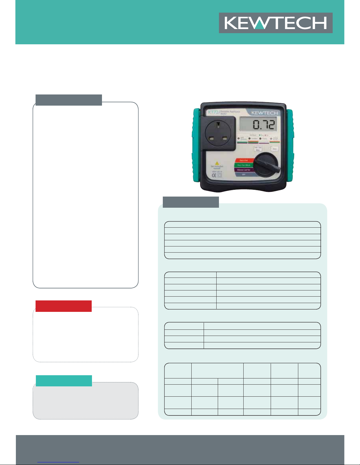
KT72
PAT TESTER WITH AUTO
TEST SEQUENCES
• Performs Earth bond at 200mA at both +ve and -ve
polarities (IT appliance safe)
• 250V / 500V insulation test voltages
• Substitute leakage tests
• Single rotary dial position initiates test sequence
• Class I IT 200mA Earth Bond
• Class II
• Extension lead test – including polarity
• LED indication of pass / fail as well as a result display
• Automatic check if appliance is switched on or not
• Test 110V appliances for earth bond and insulation
(with appropriate test adaptor).
• Tests in accordance with
the IEE Code of Practice
• Powered by batteries
• Earth lead
• Instruction Manual
• Calibration Certificate
• Extension Lead Adaptor
• Pass & Fail labels
• PATLOG1 PAT record log book for multiple sites
• PATLOG2 for single sites, including pass labels
MEASUREMENT OF INSULATION RESISTANCE - R
INS
Rating 250V / 20MΩ and 500V / 20M Ω
Measuring range 0.1~19.99M Ω
Resolution 10kΩ
Rated voltage 250V/500V DC(-0%/+30%) @250k Ω/500kΩ
Short-circuit current 2.5mA DC or less
Accuracy ± (2%rdg+3dgt)
Protective conductor Insulation Substitute Polarity
resistance resistance Leakage
current
LED Colour Green Amber Green Green Green
Extension Lead Rpe < 0.1 Ω Ppe < 0.1 Ω Rins > 1M Ω Cont < 10 Ω
< 0.3 Ω
Class I Rpe < 0.1 Ω Ppe < 0.1 Ω Rins > 1M Ω Leak < 0.75mA
< 0.3 Ω
Class II Rins > 2M Ω Leak < 0.25mA
THRESHOLD AND DISPLAY
Test function Leakage current test
Measuring range 0.1-12.00A rms
Resolution 0.01mA
Accuracy ±(3%rdg ± 5dgt)
SUSTITUTE LEAKAGE CURRENT
Test function IT 200mA continuity test
Measuring range 0 - 19.99 Ω
Resolution 10mΩ
Open-circuit voltage 5V
Measuring current 200mA DC (nominal)
Accuracy ±(3%rdg ± 5dgt)
MEASUREMENT OF PROTECTIVE CONDUCTOR RESISTANCE - R
PE
ACCESSORIES
PRODUCT DATA SHEET
SPECIFICATIONS
OPTIONAL
KT72
PAT Tester with
Auto Test Sequence
t: 01494 792 212
kewtechcorp.com
e: sales@kewtechcorp.com

1
Electricity is dangerous and can cause injury and death. Always treat it
with the greatest of respect and care. If you are not quite sure how to
proceed, then stop, take advice from a qualified person.
This instruction manual contains warning and safety rules which must be
observed by the user to ensure safe operation of the instrument and
maintain it in a safe condition. Therefore, read through t
hese operating
instructions before using the instrument.
IMPORTANT:
This instrument must only be used by a competent and trained person
and operated in strict accordance with these instructions.
KEWTECH will not accept liability for any damage or injury caused
by misuse or non-compliance with the instructions or with the safety
procedures.
It is essential to read and to understand the safety rules con
tained in
these instructions and with the safety procedures.
The symbol # indicated on the instrument means that the user must refer
to the related sections in the manual for safe operation of the instrument.
Be sure to carefully read instructions following each symbol # in this
manual.
#
DANGER is reserved for conditions and actions that are likely
to cause serious or fatal injury.
#
WARNING is re
served for conditions and actions that could
cause serious or fatal injury.
#
CAUTION is reserved for conditions and actions that could
cause minor injury or instrument damage.
Note: This indicates information that is essential for handling the
instruments or should be noted in order to familiarise yourself
with the instruments operating procedures and/or functions.
#
DANGER
● Do not apply any vol
tage to the test socket and test lead of this
instrument.
● For safety reasons, only use the Test Leads designed to be
used with this instrument and recommended by KEWTECH.
● Do not tou c h the device unde r te st whilst test i ng is in
progress.
1.Safe testing
2
#
DANGER
● Sinc e a high voltage of 250V or 500V is be i n g out p u t
continuously, when measuring insulation resistance, the user
may get an electrical shock. Any capacitors in the appliance
under test may become charged during testing and may
contain hazardous voltages do not touch them.
● Do not touch the metal part of the Test Lead with crocodile clip
(M-7242) whilst testing is in progress.
● Do not
touch or disconnect the appliance under test until
testing is completed.
#
WARNING
● Never open the instrument case – because dangerous voltages
are p resent. Only fully trained an d compete nt electrical
engineers should open the case.
● If abnormal conditions of any sort are noted (such as a faulty
display, unexpected readings, broken case, cracked test leads,
etc) do not use the instrument and re
turn it to your distributor
for inspection and repair.
● Never attempt to use the instrument if the instrument or your
hands are wet.
#
CAUTION
● When using Test Leads with the crocodile clip, be sure to
check the crocodile clip is firmly connected to the metal part of
the device under test. Otherwise, inaccurate measurements or
arcing at the contacts may occur.
● The recomended rated measuring vol
tage for the insulation
test is 500V DC.
If this voltage seems too high for the appliance under test
contact the appliance manufacturer for advice. The IEE Code of
Practice allows for a touch current test (substitute leakage) or
a 250V insulation test where a 500V insulation test cannot be
carried out.
● We are not liable for loss of data on PC during testing with this
instrument. The appliance
under test is powered on during
most tests, but please turn it to the OFF position after testing.
● Use a very slightly damp cloth for cleaning the instrument. Do
not use abrasives or solvents.
● Whe n t he measurement fun ction is comp leted, turn th e
function switch back to the OFF position to turn off.
● Thi s i nstru ment wi ll auto matic ally be powere d o ff afte r
approximately 10 minutes if no key oper
ation is carried out.
● If the instrument will not be used for a prolonged period,
remove the batteries.
Safe testing
3
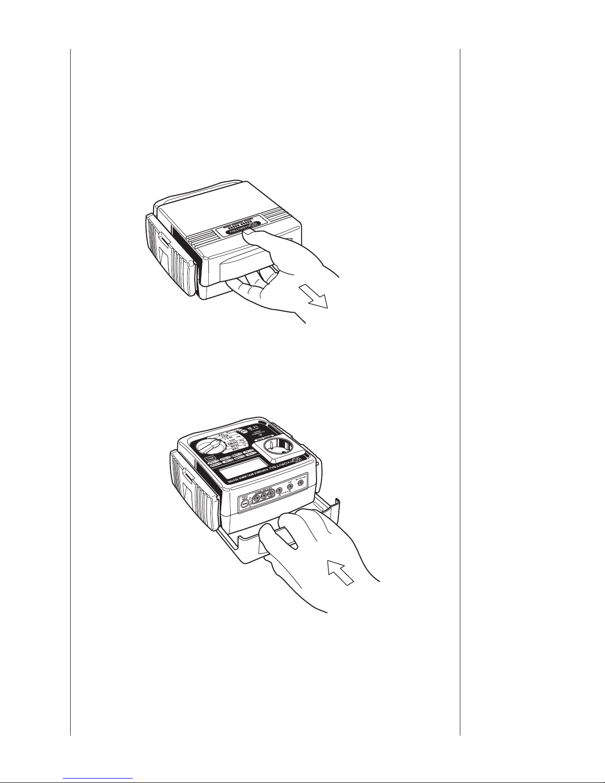
The KT72 has a dedicated cover to protect against an impact from the
outside and to prevent the fascia, the LCD, and the connector socket from
becoming dirty. The cover can be detached and put on the backside of
the main body during measurement.
2.1 Method of removing the cover
2.2 Method of storing the cover
Fig.1
Fig.2
2. Procedure
of removing
cover

4
3.1 Product summary
The KT72 is a hand-held battery powered portable appliance tester,
performing three functions to ensure the Safety of Class I and Class
II appliances. Readings are displayed on a large liquid crystal display
(LCD) below which are four bicolour LEDs, which unambiguously
display a pass or fail indication for results dictated by the IEE Code of
Practice.
This instrument is s
uitable for performing tests as required by the
following standard.
The IEE Code of Practice for In-service Inspection and Testing of
Electrical Equipment: 2007
This instrument is designed to check the electrical safety of appliances
of Class I and Class II categories.
As a guide the two categories are defined as follows:
Class I : Appliances which have functional insulation throughout
and an
earth connected case. These are often described as earthed
appliances.
Class II: Appliances which have both functional and additional insulation
where any metal parts cannot become Live under fault
conditions, often referred to as double insulated.
3. Product
summary and
explanation

5
3.2 Test Functions
KT72 has the following features.
Function Tests of contents
Class I Test 200mA
● Protective conductor resistance (Test current
200mA DC nominal)
● Insulation (Test voltage 250V DC or 500V
DC)
● Substitute leakage current test
Class ll Test
● Insulation (Test voltage 250V DC or 500V
DC)
● Substitute leakage current test
Extension Lead test
● Protective conductor resistance (Test current
200mA DC nominal)
● Insulation L/N-PE (Test voltag
e 250V DC or
500V DC)
● L-N Short
● Polarity
3.3 Features
● Auto-testing
● Checks for whether the appliance is correctly switched ON or not
● Selection for 250V or 500V for the insulation resistance test.
● Null function for the earth bond test lead.
● Over range indication on the LCD.
● Pass / fail indication of tests by LEDS and by a buzzer.
● Auto-power-off function
Product
summary an
d
explanation
6
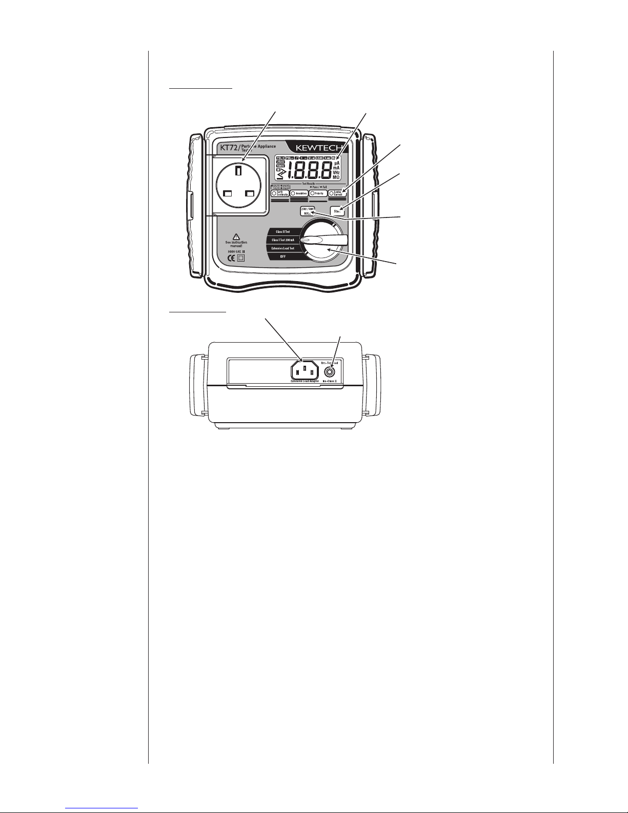
3.4 Instrument layout
Front View
End View
⑴ Test socket
Insert the mains plug of the appliance to be tested in to this socket for
the protective conductor resistance, insulation resistance, substitute
leakage current test and extension lead test.
⑵ LCD
Measured value is displayed
⑶ LED for test result
When the value of protective con ductor res istance, insulation
resistance and substitu
te leakage current exceeds the limit dictated by
applicable standards, LEDs light up in red. When it is within the limit,
the LEDs light up in green. (For protective conductor resistance, the
LED can light orange, for details please refer to the note in section 6.1:
Class I Test.)
⑷ Start switch
A measurement starts by pressing this switch.
(1) Test socket (2) LCD
(3) LEDs for test result
(4) Start switch
(5) NULL /250V-500V
switch
(6) Function switch
(7) Terminal for Extension lead adaptor
(8) Terminal for RPE – Test lead
Fig.3
Product
summary and
explanation

7
⑸ NULL/250V-500V switch
● The rotary dial has to be set to a Class l or Extension Lead test for
this button to be used to zero out the test lead resistance.
● The rotary dial has to be set to Class ll for this button to be used to
select either 250 V or 500V insulation test voltage
⑹ Function switch
Select a function with this switch.
⑺ Terminal for Extension lead adaptor
For use with the KAM
P S (UK) extension lead adaptor.
⑻ PE / Class II insulation probe
Connect the Test Lead with crocodile clip (M-7242) (fig 4) to this
terminal for the measurement of protective conductor resistance and
Class II insulation, and clip the metal parts of the appliance under test
with the crocodile clip.
⑼ Test Lead with crocodile clip M-7242
⑽ Extension leads adaptor KAMP S (UK)
This is for connectin
g the instrument and a mains extension lead.
⑾ Earth pin adapter M-8251
Product
summary and
explanation
Fig.4
IEC Connector
Fig.5
Fig.6

8
3.5 Explanation for indications
LCD Display
Product
summary and
explanation
RPE Continuity indication
(with both polarities)
Appears when the batteries are
becoming low
Leakage current indication
Null indication
Unit indication
Over range display: “ >” is displayed on the LCD.
Insulation measurement voltage
Fig.7

9
List of display message
Disp layed wh en the val ue at prelim inary
measurement for the protective conductor
r e s i s t a n c e e x c e e d s 2 0 Ω, a n d t h e
measurement cannot be carried out.
Displayed when th e protecti ve conductor
resistance exceeds the threshold value. (*1)
Displayed when appliance under test is
switched off.
Displayed when t he insulation resistance
between LN-E is less than the threshold value.
Displayed when the leakage current exceeds
the threshold value.
Displayed when L-N is close to short during an
Extension lead test.
Displayed when the resistance between L-L
exceeds 10Ω during an Extension lead test.
Displayed when the resistance between N-N
exceeds 10Ω during an Extension lead test.
(*1): Extension leads and appliances with long mains leads have a
greater resistance allowance for earth continuity. Please refer to the
table.1 on page 11.
3.6 Applicable standards
Instrument operation
The IEE Code of Practice for In-service Inspection and Testing of
Electrical Equipment: 2007
Safet
y
IEC/EN61010-1 CAT.III 300V-instrument
IEC/EN61010-031 CAT.III 300V-test lead
EMC
EN61326 (EN55022/EN61000-4-2, 4-3)
Product
summary and
explanation

10
4.1 General specification, measuring range and accuracy
Measurement of earth continuity (protective conductor resistance) - RPE
Test function 200mA continuity
Measuring range
0 ~ 19.99Ω
(including pre-set Null values) (*2)
Resolution 10mΩ
Open-circuit voltage 5V DC
Measuring current 200mA DC (nominal)
Accuracy ± (3%rdg+5dgt)
(*2): Test lead resistance of 3Ω or less can be cancelled by NULL
function.
Measurement of insulation resistance - RINS
Output voltage 250V 500V
Measuring range 0.1~19.99MΩ
Resolution 10kΩ
Open-circuit voltage 250V (+30%/-0%) 500V (+30%/-0%)
Nominal current
1mA DC min.
@250kΩ
1mA DC min.
@500kΩ
Short-circuit current 2.5mA DC or less
Accuracy ± (2%rdg+3dgt)
Measurement of substitute leakage current test - LEAK
Test function Leakage current test
Measuring range 0.1~12.00mA rms, 50Hz AC
Resolution 0.01mA
Accuracy ± (3%rdg+5dgt)
4.2 Threshold and display
Function
Earth
Continuity
Insulation
Resistance
Polarity
Leakage
Current
Class I 200mA
RPE ≦ 0.1Ω(*3)
RINS ≧ 1MΩ
−
LEAK ≦ 0.75mA
Class ll
−
RINS ≧ 2MΩ
−
LEAK ≦ 0.25mA
Extension Lead
RPE ≦ 0.1Ω(*3)
RINS ≧ 1MΩ
Cont ≦ 10Ω
−
(*3): Extension leads and appliances with long mains leads have a
greater resistance allowance for earth continuity. Please refer to the
table 1 on next page.
¤ Green (RPE ≦ 0.1Ω) = Pass for all ap
pliances
¤ Orange (0.1Ω< RPE < 0.3Ω) = Pass for appliances with extended
mains leads
¤ Red (RPE ≧ 0.3Ω) = Fail
4.Specification

11
table.1: Summary of flexible table resistance rounded to two decimal places*
Nominal Conductor csa
– should be marked on
flexible cable
(mm2)
Length
(m)
Resistance
(at 20° )
(Ω)
Max. carrying
current
(A)
0.5
1 0.04
3
2 0.08
3 0.12
4 0.16
0.75
1 0.025
6
2 0.05
3 0.08
4 0.10
5 0.13
1.0
1 0.02
10
2 0.04
3 0.06
4 0.08
5 0.10
1.25
1 0.015
13
2 0.03
3 0.05
4 0.06
5 0.08
1.5
1 0.01
15
2 0.03
3 0.04
4 0.05
5 0.06
2.5
1 0.01
20
2 0.01
3 0.02
4 0.03
5 0.04
4
1 0.00
25
2 0.01
3 0.01
4 0.01
5 0.02
*For flexible cables to BS 6500 or BS 6360
Note. For further information on p
rotective conductor resistance and
testing of portable appliances can be found in the Code of Practice
for In-service Inspection and Testing of Electrical Equipment
published by the IEE.
Specification

12
4.3 Reference test condition
Unless otherwise specified, this specification is dependent on the
following conditions.
⑴ Ambient temperature: 23±5˚C
⑵ Relative humidity: 45 ~ 75%
⑶ Attitude: Horizontal
⑷ Altitude: 2000m or less
Operating temperature and humidity range
0ºC ~ +40ºC Relative humidity: 85% or less (no condensation)
Storage temperature and humidity range
-20ºC ~
+60ºC Relative humidity: 85% or less (no condensation)
Power supply
AA-size R6 / LR6 (HR6) 1.5V (1.2V) batteries x 8
Use of alkaline batteries is recommended. (AA-size nickel hydride
rechargeable batteries are also usable.)
Maximum rated power
Approx. 4.5VA
Outer dimension and weight
Outer dimension: 185(L) × 167(W) × 89(D)mm
Weight: Approx. 1.1kg (instrument with batter
ies)
Symbols used on the instrument:
Equipment protected throughout by DOUBLE INSULATION or
REINFORCED INSULATION
#
Caution (Refer to the accompanying instruction manual)
Fuse
This symbol indicates a fuse.
Battery
This symbol indicates a battery.
Ground
This symbol indicates ground (earth).
Specification

13
5.1 Visual inspection
Before starting a measurement, the user should undertake visual
checks on the mains cord, case and that the correct type and rated fuse
is fitted to the appliance under test. There should also be no evidence
of damage of a nature that may impair the electrical safety of the
appliance.
5.2 Battery Voltage Check
If the bat teries fall below the normal operating voltage, the
" "
icon turns on. If the Low battery icon is indicated (Fig.7), replace the
batteries according to 7. for Battery and Fuse Replacement.
5.3 Null setting
The IEE Code of Practice pass level for Protective conductor resistance
is 0.1Ω, which is a low value. So even the resistance of Test Leads will
affect the measurement result.
The KT72 can cancel the resistance of the test lead by pressing t
he
NULL|250V/500V
switch. The procedure of Null setting is shown
below.
The Null function is held in memory even when the instrument is turned
off, so theres no need to Null the lead resistance every time.
However, when replacing fuses or test leads, it is recommended to do a
Null setting again.
Note
● Null setting is possible at both Class l Test and Extension Lead
Test. However, only one Null value can be
held in memory. For
example, when the Null setting is carried out at Class l Test, the set
value will also be used for Extension Lead Test (unless it is reset).
● After the function switch is turned to the OFF position, the set Null
value is still held in the internal memory.
5. Preparation
before a
measurement

14
5.3.1 Null setting for Class I Test
⑴ Set the function switch to Class l Test 200mA function.
⑵ Insert the Earth pin adapter (M-8251) in to the end of the Earth
terminal of the Test socket.
⑶ Connect the Test lead with the crocodile clip (M-7242) to the
Terminal for RPE-Test Lead of the instrument, and attach the
crocodile clip on to the earth pin. (Fig.8)
⑷ Press the
NULL|250V/500V
switch whilst maintaining contact
between the Test Lead and the earth pin adapter, the resistance of
the Test Lead will be displayed on the LCD as shown in Fig.9 for
2sec.
Then, the instrument cancels the resistance value of the Test Lead
and adjusts the displayed value to 0.00 as shown in Fig.9.
At this point the
NULL
icon is displayed in the LCD.
The Null setting cannot be done when the test lead resistance is 3Ω
or more.
A message no appears to indicate that the resistance is exceeding
the Null setting range.
Display at Null setting
⑸ Null setting can be released by pressing
NULL|250V/500V
switch
for 2sec. The
NULL
mark on the LCD will disappear when Null
setting is released.
Preparation
before a
measurement
M-7242
M-8251
Earth pin
Set the Function switch to
“Class I Test 200mA”
Fig.8
Fig.9
15
5.3.2 Null setting for Extension Lead Test
⑴ Set the function switch to Extension Lead Test function.
⑵ Connect the Extension lead adaptor KAMP S (UK) as indicated in
Fig.10, and then follow the procedure described at clause 5.3.1 (4).
⑶ Follow the procedure described at clause 5.3.1 (5) to cancel the Null
setting.
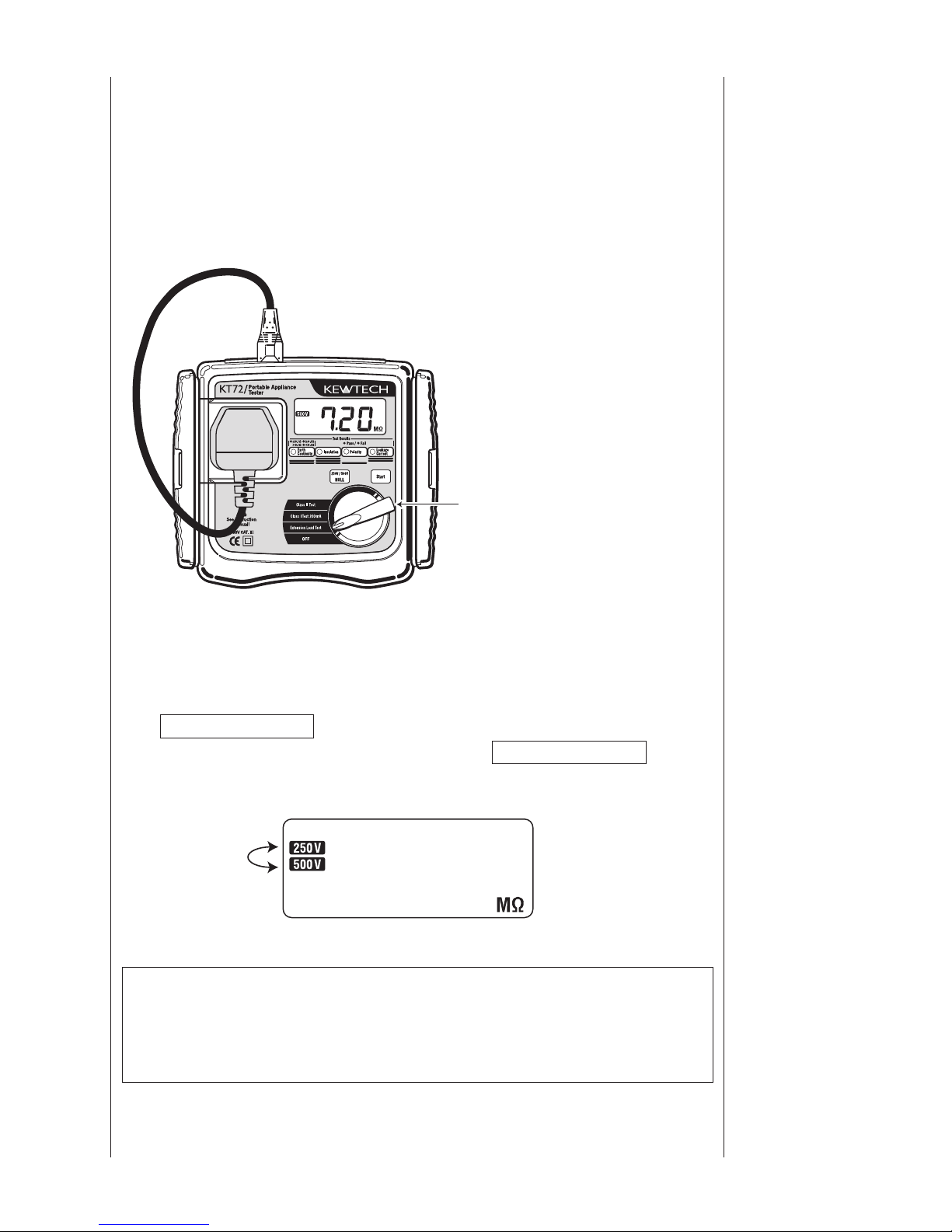
5.4 Voltage setting for insulation resistance measurement
(How to chang
e between 250V and 500V)
⑴ Set the function switch to the Class II Test function, and press the
NULL|250V/500V
switch. The LCD display will change to indicate
the voltage selected. By pressing the
NULL|250V/500V
switch,
250V and 500V can be changed over.
Note
● The Insulation test voltage setting is saved and kept in the internal
memory of the instrument and is maintained even after switching
the instrument off.
Set the Function switch to
“Extension Lead Test”
Fig.10
Preparation
before a
measurement
Fig.11
16
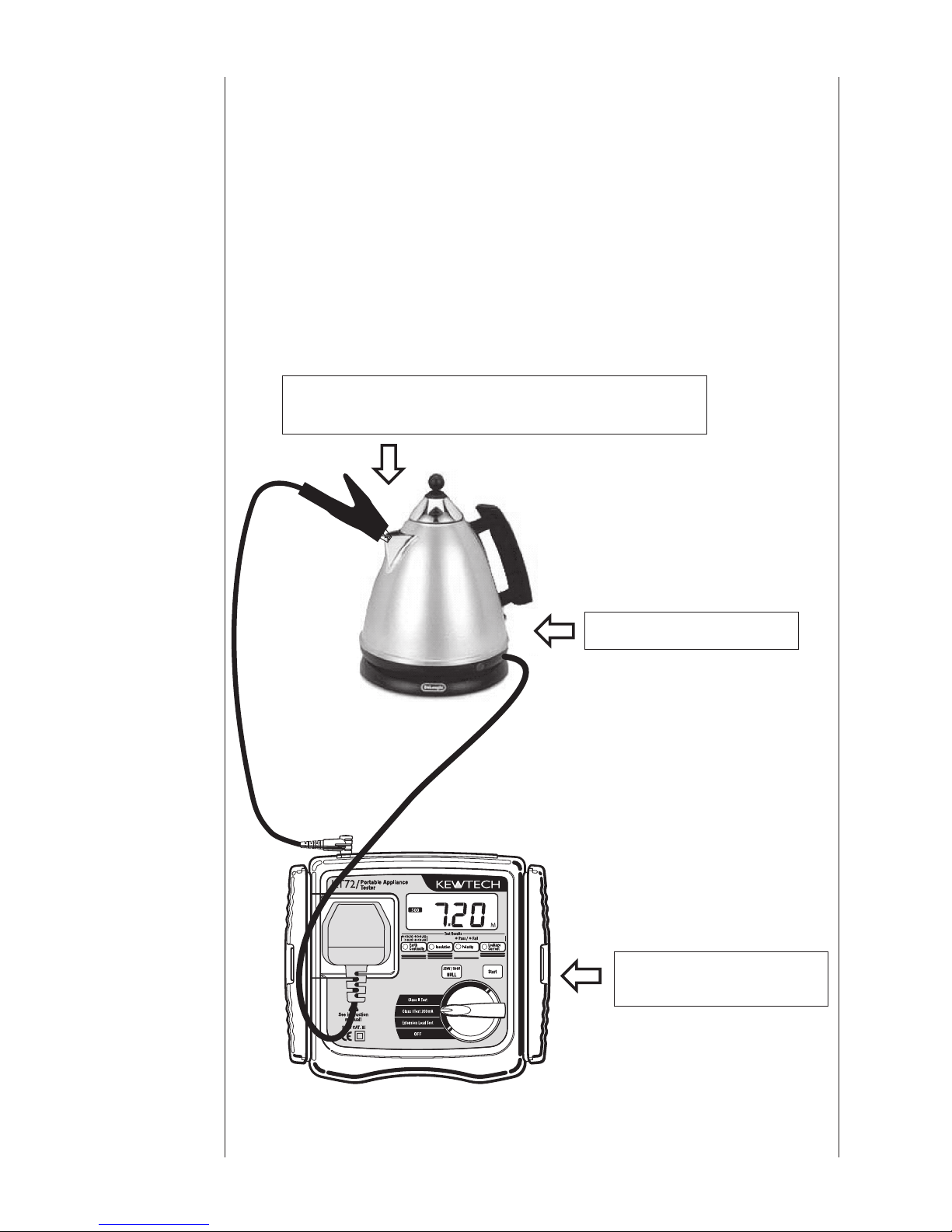
Connect to exposed metal parts but not rotating
parts or heating elements.
Switch ON the power.
Set the function switch to
Class 1 test 200mA
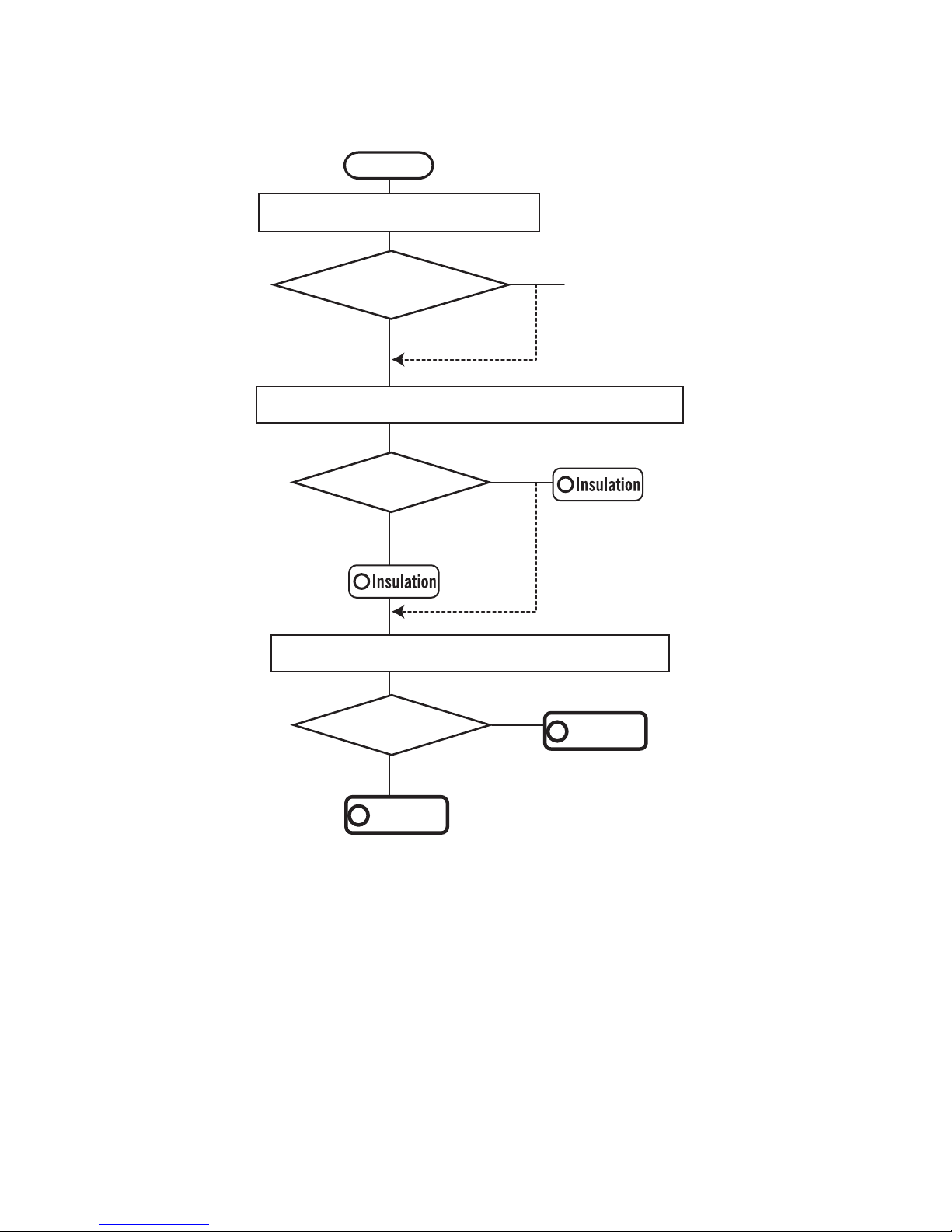
6.1 Class I Test (200mA earth bond test)
The purpose of the test carried out for Class I appliances is to check
the resistance of earth continuity from exposed metal parts and the plug
is below a certain level and the insulation resistance between live and
neutral connected together and earth is above 1MΩ. This test sequence
also conducts a substitute leakage current test on an appliance. To
co
nduct a test, connect the mains plug of the appliance to the test
socket (1) described in clause 3.4. INSTRUMENTS LAYOUT and the
PE probe to terminal (8).
Use the following setups, depending upon the type of appliance.
6. Measuring
method
Fig.12
17
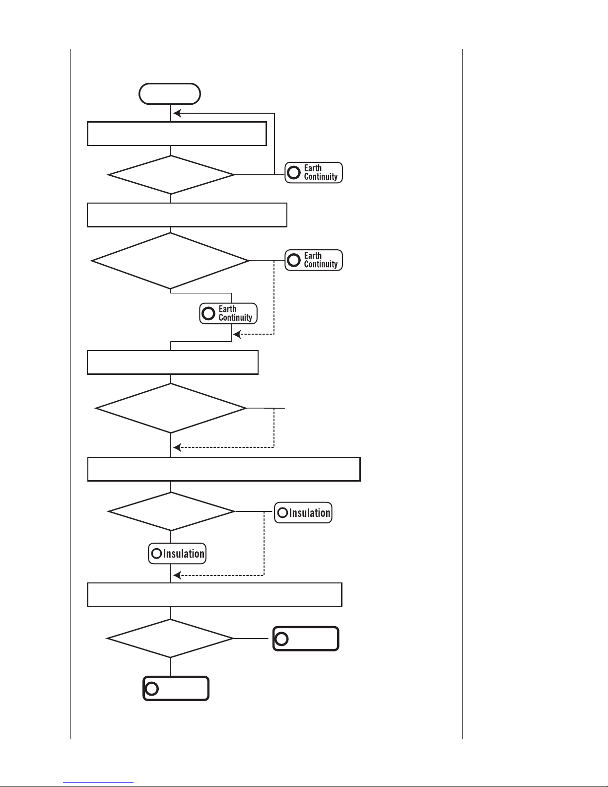
Measuring
method
Check earth connections
and press start again.
(*5)
(*4)
Lights up in red
No
Yes
Yes
Yes
(1). Preliminary measurement
No
(4). Insulation resistance between L/N and PE.
Lights up
in green
Value of (2),(4) and (5) will be alternately displayed on the LCD.
No
Re-start
Can proceed to the next step
by pressing the Start switch
again even if the result was
a fail
Start
Class I Test Flowchart
Lights up in red
Lights up
in green
No
Re-start
(2). Protective conductor resistance.
Lights up in red
Re-start
(*6)
(5). Leakage current between L/N and PE.
No
RPE≦20Ω?
“no”→“Con” is displayed
alternately on the LCD.
RPE≦0.1Ω?
(0.1Ω<RPE<0.3Ω?)
Lights up in green or
if the resistance
is:between >0.1 and
< 0.3Ω it lights orange
“no” →“Con”→“value” will
be repeated on the LCD.
(*7)
(3). Appliance switch test
Is the appliances
switched on?
“oFF”→“ ? ” is displayed
alternately on the LCD.
Yes
Leakage
Current
Leakage
Current
PASS
LEAK≦0.75mA?
Stop the test and
“no”→“LEA”→“value” will be
repeated on the LCD.
LnE
≧
1MΩ ?
Lights up in red
“no”→“LnE”→“value” will be
repeated on the LCD.

18
Note
● (*4) This instrument conducts a Preliminary measurement before
conducting Protective conductor resistance measurement. In
case that the resistance value exceeds 20Ω, no and Con are
alternately displayed on the LCD, and the next measurement in the
sequence will not be conducted.
● Extension leads and appliances with long mains leads have a
greater resistance allowance for earth continui
ty. Please refer to the
table.1 on page 11.
● (*5)This instrument displays the test results of protective conductor
resistance as follows.
Green (RPE≦0.1Ω) = Pass for all appliances
Orange (0.1Ω<RPE<0.3Ω) = Pass for appliances with extended
mains leads
Red (RPE≧0.3Ω) = Fail
● (*6)This instrument has a Re-Start function.
It can proceed to the next step by pressing the Start switch again
ev
en if the result was a fail.
● (*7) When conducting Insulation resistance test and Leakage
current test, the appliance under test must be being switched ON.
This instrument automatically detects the condition of power switch
ON. In case that the condition of power switch ON cannot be
detected, oFF and ? are alternately displayed on the LCD, and
the test will be stopped. In this case, pleas
e make sure the power
switch of the appliance is ON.
● Th i s inst r umen t wi ll aut o mati c a lly be po w ered o f f afte r
approximately 10 minutes if no key operation is carried out.
#
CAUTION
● Follow the procedure described in 5.3, 5.4 and undertake the
NULL and Voltage setting before taking a measurement.
● The crocodile clip must make good contact with the enclosure
of the appliance.
●
When the terminal is open or the resistance value exceeds the
measuring range, or the leakage current exceeds the measuring
range the > mark (over range display) appears on the LCD.
● Do not touch the appliance under test whilst testing is in
progress. Since a high voltage of 250V or 500V will be present
and the user may get an electrical shock.
● Whe n t he measurement fun ction is comp leted , turn th e
function s
witch back to the OFF position to turn off.
Measuring
method
19
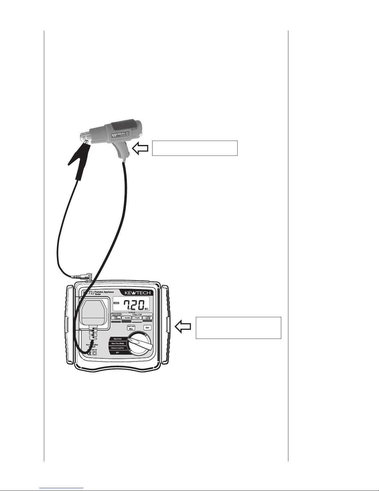
6.2 Class ll Test
The Class ll appliances have the indication of DOUBLE INSULATION
or the symbol. The class ll insulation test is to check the insulation
resistance and leakage current of the appliances is within the range
defined in the standards.
Measuring
method
Switch ON the power.
Set the function switch to
the Class II position.
Fig.13
20
Class Il Test Flowchart
No
Value (2) and (3) will be alternately displayed on the LCD.
Yes
(2). Insulation resistance between L/N and PE.
(1). Appliance switch test
(*7)
Yes
Yes
No
Start
(*6)
Lights up in red
Lights up
in green
No
(3). Leakage current between L/N and PE.
When the resistance
between L-N is about
100kΩ or more
“ oFF”→“ ? ” is displayed
alternately on the LCD.
Is the appliance
switched on?
Re-start
Re-start
LnE ≧2MΩ?
Lights up
in green
Lights up in red
“no”→“LnE”→“value” will
be repeated on the LCD.
PASS
LEAK≦0.25mA?
Stop the test and
“no”→“LEA”→“value” will be
repeated on the LCD.
Leakage
Current
Leakage
Current
Measuring
method

21
Note
● (*6)This instrument has a Re-Start function.
It can proceed to the next step by pressing the Start switch again
even if the result was a fail.
● (*7) When conducting Insulation resistance test and Leakage
current test, the appliance under test must be being switched ON.
This instrument automatically detects the condition of power switch
ON. In case that the condition of power switch O
N cannot be
detected, oFF and ? are alternately displayed on the LCD, and
the test will be stopped. In this case, please make sure the power
switch of the appliance is ON.
● Th i s inst r umen t wi ll aut o mati c a lly be po w ered o f f afte r
approximately 10 minutes if no key operation is carried out.
#
CAUTION
● Follow the procedure described in 5.4 and undertake the
Voltage setting before taking a m
easurement.
● The crocodile clip must make good contact with the enclosure
of the appliance.
● When the terminal is open or the resistance value exceeds
the measuring range, or the leakage current exceeds the
measuring range the > mark (over range display) appears
on the LCD.
● Do not touch the appliance under test whilst testing is in
progress. Since a high voltage of 250V or 500V will be pre
sent
and the user may get an electrical shock.
● Whe n t he measurement fun ction is compl eted, turn th e
function switch back to the OFF position to turn off.
Measuring
method

22
6.3 Extension Leads Test
This test is for extension leads, and checks for;
● Protective conductor resistance.
● Insulation resistance between L/N and PE.
● Short test between L and N.
● Polarity check of the Line and Neutral terminals of the plug and
socket.
Test procedure and the connection are as follows.
Extension leads adaptor
KAMP S (UK)
Set the function switch to
the extension lead test position
Fig.14
Measuring
method

23
Measuring
method
Check earth connections
and press start again
(*5)
(*4)
Lights up in red
No
Yes
Yes
Yes
(1). Preliminary measurement
No
(4). Short test between L and N.
Lights up
in green
Value of (2) and (3) will be alternately displayed on LCD.
No
Re-start
Start
Extension Leads Test Flowchart
Lights up in red
Lights up
in green
No
Re-start
(2). Protective conductor resistance test.
Re-start
(*6)
(5). Polarity test between L-L and N-N.
No
RPE≦20Ω?
RPE≦0.1Ω?
(0.1Ω<RPE<0.3Ω?)
Lights up in green or
if the resistance
is:between >0.1 and
< 0.3Ω it lights orange
(3). Insulation resistance test between L/N and PE.
Yes
PASS
Lights up in red
Lights up in red
“no”→“Con” is displayed
alternately on the LCD.
Lights up in red
“no” →“Con”→“value” will
be repeated on the LCD.
“no”→“LnE”→“value”will
be repeated on the LCD.
“no”→“Sht” is displayed
alternately on the LCD.
“no”→“L-L”→“value”
or “no” →“n-n” →“value”
will be repeated on the LCD
.
LnE
≧
1MΩ?
L-N
≧
100kΩ?
L-L & N-N≦10Ω?
Polarity
Polarity
24
Note
● (*4) This instrument conducts a Preliminary measurement before
conducting the Protective conductor resistance measurement. In
the case that the resistance value exceeds 20Ω, no and Con
are alternately displayed on the LCD, and the next measurement in
the sequence will not be conducted.
● Extension leads and appliances with long mains leads have a
greater resistance allowance for earth
continuity. Please refer to the
table.1 on page 11.
● (*5)This instrument displays the test results of the protective
conductor resistance as follows.
Green (RPE≦0.1Ω) = Pass for all appliances
Orange (0.1Ω<RPE<0.3Ω) = Pass for appliances with extended
mains leads
Red (RPE≧0.3Ω) = Fail
● (*6)This instrument has a Re-Start function.
It can proceed to the next step by pressing the Start switc
h again
even if the result was a fail.
● Th i s inst r umen t wi ll aut o mati c a lly be po w ered o f f afte r
approximately 10 minutes if no key operation is carried out.
#
WARNING
● Do not connect the M-7242 to main power supply. And do not
apply any voltage to the test socket.
#
CAUTION
● Follow the procedure described in 5.3 and undertake the Null
setting before taking a measurement, but use the short KAMP
S
lead instead of the M-7242 test lead, by plugging the KAMP
S.into the Extension Lead Adaptor terminal and the UK socket
on the front of the unit.
● When the terminal is open or the resistance value exceeds the
measuring range, > (over range display) appears on the
LCD.
● Do not tou c h the device unde r te st whilst test i ng is in
progress. Since a high voltage of 250V or 500V will be present,
the
user may get an electrical shock.
● Whe n t he measurement fun ction is compl eted, turn th e
function switch back to the OFF position to turn off.
Measuring
method

25
#
DANGER
● N ev e r a t t e m p t to r e p l ac e b a t te r i e s wh i l e m a k i n g
measurements. When replacing the Fuse, use one with the
same specification.
#
WARNING
● To avoid electrical shock hazard, disconnect the Test Leads
from the instrument before opening the Battery Compartment.
Screw and fasten the cover before using the instrument again.
#
CAUTION
● Do not mix new and old batteries. Install batteries in the
o
rient a tion as shown inside the Bat t ery Co mpartmen t ,
observing correct polarity.
● If the instrument is not to be used for a prolonged period,
remove the batteries.
● When disposing of the old batteries, please follow your local
regulations.
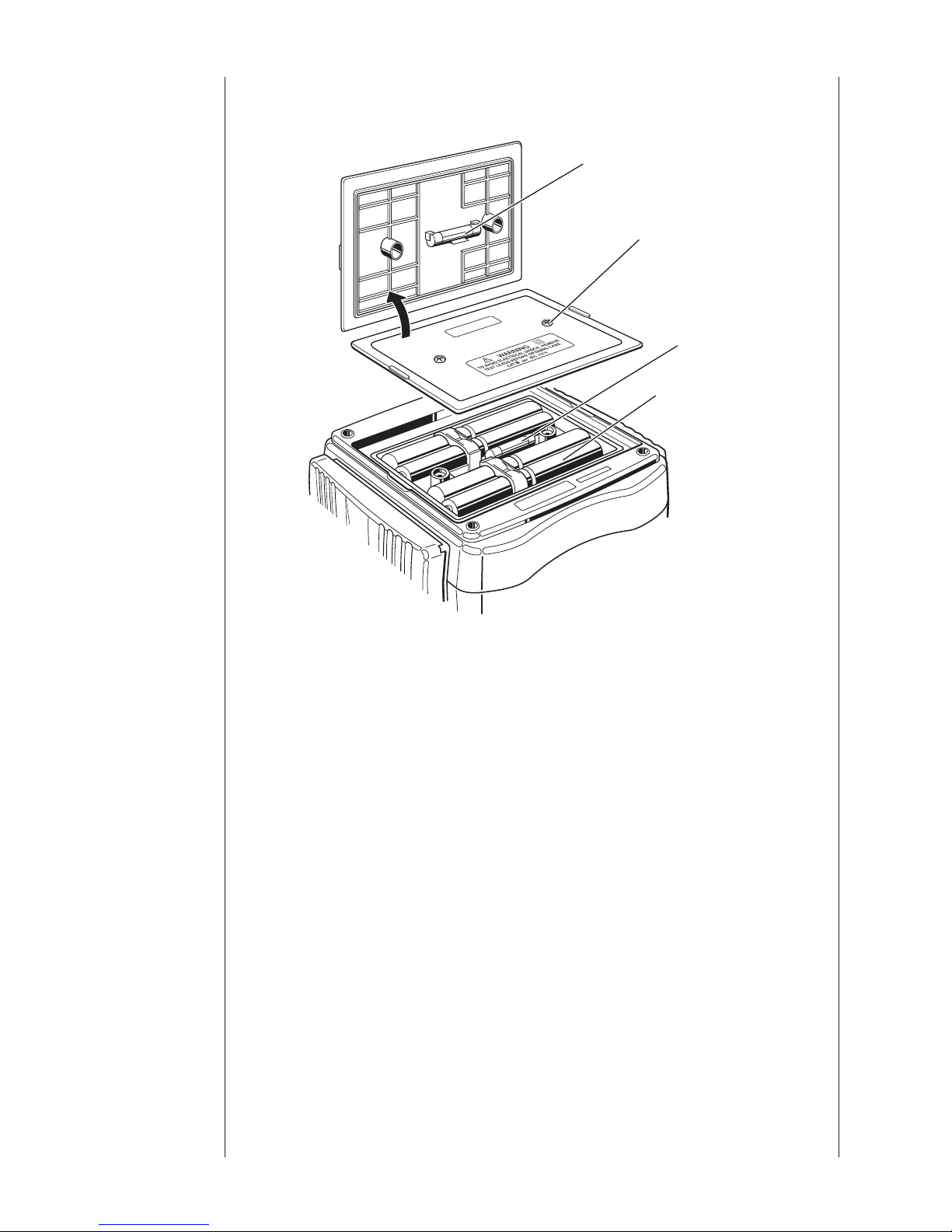
7.1 Battery Replacement
⑴ Set the Range Switch to the OFF position, and disconnect the Test
Leads from the instrument.
⑵ Unscrew the Battery-Compartment
-fixing screws, and remove
the Cover and replace the batteries with new ones. Replace all 8
batteries.
⑶Fix the Cover after replacing batteries and screw up the Cover.
7.2 Fuse Replacement
⑴ Set the Range Switch to the OFF position, and disconnect the Test
Leads from the instrument.
⑵ Unscrew the Battery-Compartment-fixing screws, and remove the
Cover.
Replace the fuse with a new one
. (Fig.15)
Fuse Spec : T 3.15A / 500V, dia. 6.35 x 32mm.
⑶ Fix the Cover after replacing a fuse and screw up the Cover.
7. Battery
and Fuse
Replacement
26
Battery
and Fuse
Replacement
Spare Fuse
Screw
Fuse
Battery
Fig.15

27
The strap and test lead case can be attached to the instrument as
below.
Pass the strap belt down through the side panel of the main body from
the top, and up through the slots of the test lead case from the bottom.
(Fig. 16).
Pass the strap through the buckle, adjust the strap for length and
secure.
Use a very slightly damp cloth for cleaning the instrument. Do not use
abrasives or
solvents.
8. Case and
strap
assembly
9. Maintenance
Fig.16

 Loading...