

Page 1

KT71 /
POWERED BY
Portable Appliance
Tester
Instruction Manual
Page 2

CONTENTS
1. Safe testing ………………………………………………………………… 1
2. Procedure of removing cover …………………………………………….. 3
2.1 Method of removing the cover ………………………………………... 3
2.2 Method of storing the cover …………………………………………... 3
3. Product summary and explanation ……………………………………… 4
3.1 Product summary …………………………………………………….... 4
3.2 Test function ……………………………………………………………. 5
3.3 Features ………………………………………………………………... 6
3.4 Instrument layout …………………………………………………….... 6
3.5 Explanation for indications ………………………………………….... 9
3.6 Applicable standards …………………………………………..…….. 10
4. Specification ………………………………………………………………. 11
4.1
General specification, measuring range and accuracy
4.2 Threshold and display ……………………………………………….. 12
4.3 Reference test condition …………………………………………….. 12
5. Preparation before a measurement …………………………………….. 13
5.1 Visual inspection ……………………………………………………… 13
5.2 Connection to main power supply ………………………………….. 13
5.2.1 Connection of mains cord ………………………………………. 13
5.2.2
5.2.3
5.2.4
Check the warning display of mains power voltage
Null setting (Protective conductor resistance function)
Voltage setting for insulation resistance measurement
………………… 11
………………… 14
………………... 14
………………... 16
6. Measuring method ……………………………………………………….. 17
6.1
Class I Test (Common function for both IT200mA and 20A)
6.2 Class I Test (Select the leakage current test) …………………….. 19
6.3 Class Ⅱ Test ………………………………...……………………….. 21
6.4 Class Ⅱ Test (Select the leakage current test) …………………... 23
6.5 Extension Leads Test ………………………………………………... 25
6.6 Leakage Current Test ………………………………………………... 27
7. Fuse replacement ………………………………………………………… 29
8. Case and strap assembly ………………………………………………... 30
9. Maintenance …………………………………………………..…………... 30
……………..… 17
Page 3

Electricity is dangerous and can cause injury and death. Always treat it
with the greatest of respect and care. If you are not quite sure how to
proceed, then stop, take advice from a qualified person.
This instruction manual contains warning and safety rules which must
be observed by the user to ensure safe operation of the instrument
and retain it in safe condition. Therefore, read through these operating
instructions before using the instrument.
IMPORTANT:
This instrument must only be used by a competent and trained person
and operated in strict accordance with these instructions.
KEWTECH will not accept liability for any damage or injury caused
by misuse or non-compliance with the instructions or with the safety
procedures.
It is essential to read and to understand the safety rules contained in
these instructions and with the safety procedures.
The symbol
to the related sections in the manual for safe operation of the instrument.
Be sure to carefully read instructions following each symbol
manual.
DANGER is reserved for conditions and actions that are likely
to cause serious or fatal injury.
indicated on the instrument means that the user must refer
in this
1 Safe Testing
WARNING is reserved for conditions and action s that can
cause serious or fatal injury.
CAUTION is reserved for conditions and actions that can cause
minor injury or instrument damage.
DANGER
●
This instrument can be connected only to the commercial
power of 230V+10%-10%, 50Hz.
●
For safety reasons, only use the Test Leads designed to be
used with this instrument and recommended by KEWTECH.
●Use only grounded mains outlets to supply the instrument.
Do not touch the devic e under test wh i lst testing is in
progress.
1
Page 4

2
Safe Testing
DANGER
●
Since a high voltage of 500V is being output continuously,
wh en measuri ng insulat ion r esistan ce, t he user m ay get
an electrical shock. Any capacitors in the appliance under
test may become charged during testing and may contain
hazardous voltages do not touch them.
●
When testing, always be sure to keep your fingers behind the
safety barriers on the test leads.
●
Di scon nect the instr umen t from the powe r supp ly whe n
measurement is finished.
●
Do not lea ve t he i nstrument with connected to the power
supply.
WARNING
●Never open the instrument case – because dangerous voltages
are present. Only fully trained and competent electrical engineers
should open the case.
●
If abnormal conditions of any sort are noted (such as a faulty
display, unexpected readings, broken case, cracked test leads,
etc) do not use the instrument and return it to your distributor
for inspection and repair.
●
Never attempt to use the instrument if the instrument or your
hands are wet.
CAUTION
● When using Test Leads with the crocodile clip, be sure to
check the crocodile clip is firmly connected to the metal part of
the device under test. Otherwise, inaccurate measurements or
arcing at the contacts may occur.
● The rated measuring voltage for the insulation test is 500V. DC.
If this voltage seems too high for the appliance under test
contact the appliance manufacturer for advice. The IEE Code
of Practice allows for a touch current test where an insulation
test cannot be carried out.
● When testing a faulty appliance, it may trip the circuit breaker
of main power supply during test and may cause interruption
of service. Be careful when the same main power supply is
used for PCs.
● We are not liable for loss of data on PC during testing with this
instrument. The appliance under test is powered on during
most tests, but please turn it to the OFF position after testing.
● Use a very slightly damp cloth for cleaning the instrument. Do
not use abrasives or solvents.
Page 5

3
The KT71 has a dedicated cover to protect against an impact from the
outside and to prevent the fascia, the LCD, and the connector socket from
becoming dirty. The cover can be detached and put on the back side of
the main body during measurement.
2.1 Method of removing the cover
Fig.1
2.2 Method of storing the cover
2 Procedure
of removing
cover
Fig.2
Page 6

4
3 Product
summary and
explanation
3.1 Product summary
The KT71 is a hand-held portable appliance tester, performing four
functio ns to ensure the Safet y of Class I and Class II app lia nces.
Readings are displayed on a large liquid crystal display (LCD) below
which are four bicolour LEDs, which unambiguously display a pass or fail
indication for results dictated by the IEE Code of Practice.
This ins trument is s uitab le f or performing tes ts a s required b y the
following standard.
The IEE C ode of Practice for In-servi ce Inspection and Testing of
Electrical Equipment : 2003
This instrument is designed to check the electrical safety of appliances of
Class I and Class II categories.
As a guide the IEC standard define these two categories as follows:
Class I: Appliances which have a functional insulation throughout and
an earth connected case. These are often described as earthed
appliances.
Class II: Appliances which have both functional and additional insulation
wh ere any metal part s cann ot becom e Live und er fau lt
conditions.
Page 7

5
3.2 Test Function
KT71 has the following features.
Function Tests of contents
● Pro tect ive cond ucto r res ista nce (Test
current 20A AC nominal)
Extension Lead Test
Class I Test IT200mA
● Insulation P/N-PE (Test voltage 250V DC
or 500V DC)
● Polarity (Test current 200mA DC nominal)
● Pro tect ive cond ucto r res ista nce (Test
current 200mA DC nominal)
● Insulation (Test voltage 250V DC or 500V
DC)
Product
summary and
explanation
Select Switch
+ Class I Test IT200mA
Class I Test 20A
Select Switch
+ Class I Test 20A
Class ll Test
Select Switch
+ Class II Test
Leakage Current Test
● Pro tect ive cond ucto r res ista nce (Test
current 200mA DC nominal)
●
Load current and leakage current test
● Pro tect ive cond ucto r res ista nce (Test
current 20A AC nominal)
● Insulation (Test voltage 250V DC or 500V
DC)
● Pro tect ive cond ucto r res ista nce (Test
current 20A AC nominal)
●
Load current and leakage current test
● Insulation (Test voltage 250V DC or 500V
DC)
Load current and leakage current test
●
● Load cur rent measureme nt (Maximum
appliance cu r r e n t 13A) an d le a k a g e
current test
Page 8

6
Product
summary and
explanation
3.3 Features
● Check for whether the appliance is switched ON.
●
Selection for 250V or 500V on the insulation resistance test.
● Null function for the earth bond test lead.
● Warning for the over range value by the LCD.
● Capable of judging pass/fail of tests by LEDs on the panel and by a
buzzer.
3.4 Instrument layout
Fig.3
⑴ Test socket
Insert the mains plug of the appliance to be tested to this socket for
the protective conductor resistance, insulation resistance, leakage
current test and extension lead test.
⑵ Terminal block
Connect the supplied mains cord and Test Leads to this terminal block.
⑶ Terminal for mains lead
This terminal is connected to a mains supply via M-7209.
Page 9

7
⑷ Terminal for Extension lead adaptor
For use with the KAMP S (UK) extension lead adaptor.
⑸ PE / Class II insulation probe
Connect the Test Lead with crocodile clip (M-7208) (fig 5) to this
terminal for the measurement of protective conductor resistance and
Class II insulation, and clip the metal parts of the appliance under test
with the crocodile clip.
⑹ LCD
Measured value is displayed
⑺ LED for test result
When the value of protective conductor resistance and insulation
resistance exceeds the limit dictated by applicable standards, LED
lights up in red. When it is within the limit, LED lights up in green.
⑻ Start/Stop switch
A measurement starts by pressing this switch.
Pressing the
stops the measurements.
⑼ NULL/250V-500V switch
● The rotary dial has to be set to a Class l test for this button to be
used to zero out the test lead resistance.
Start/Stop
switch again during a Leakage Current Test
Product
summary and
explanation
● The rotary dial has to be set to Class ll for this button to be used to
select either 250 V or 500V test voltage.
⑽ Function switch
Select a function with this switch.
Select switch (Applicable for Class I and Class II function)
⑾
When the function is set at the same time as the Select switch is
being pressed, the leakage test will be conducted the insulation test.
⑿ Fuse
Protected by a 600V/10A ceramic fuse (F type Φ6.3x32mm).
User can replace this fuse.
Page 10

8
Product
summary and
explanation
⒀ Mains cord (UK) M-7209
This mains cord can be connected to the mains supply so that the
instrument can derive power from it. To measure contact current, the
socket of the mains power supply has to have an earth terminal.
Fig.4
⒁ Test Lead with safety crocodile clip(M-7208) and Probe with Blade type
Prod(M-7163). The probe and crocodile clip are interchangeable.
Please use it according to a measurement use.
Probe with Blade Type Prod
Crocodile Clip
Fig.5
⒂ Extension leads adaptor KAMP S (UK)
This is for connecting the instrument and an extension lead (cord
reel).
IEC Connector
Fig.6
Page 11

9
3.5 Explanation for indications
LCD Display
Product
summary and
explanation
Insulation measurement voltage
Power supply voltage
(Live-Neutral) indication
Over range display: > is displayed on the LCD.
Leakage current indication
Load current indication
Null indication
Unit indication
Fig.7
Page 12

10
Product
summary and
explanation
List of display message
Disp layed whe n appliance under test is
switched off.
=> =>Value
=> =>Value
=> =>Value
=> =>Value
=> =>Value
or
(*1) Please note that the IEE Code of Practice states that the maximum
resistance should be no greater than 0.1 Ohms + the resistance of
the mains cable
Displayed when the protective conductor
resistance exceeds the threshold value. (*1)
Displayed when the insulation resistance
between LN-E is less than the threshold
value.
Di s p l ay e d wh e n th e le a k ag e cu rr e nt
exceeds the threshold value.
Displayed when the resistance between L-L
exceeds 10Ω at extension lead test.
Displayed when the resistance between
N-N exceeds 10Ω at extension lead test.
Displayed when the appliance under test is
undergoing the leakage current test.
D i sp la y ed w h en e m er ge n cy s t op is
operated at leakage current test.
Displayed when the mains voltage exceeds
the range of specifications (207V to 260V).
Testing will be diasabled.
3.6 Applicable standards
Instrument operation
The IEE Code of Practice for In-service Inspection and Testing of
Electrical Equipment : 2003
Safety
IEC/EN61010-1 CAT.III 300V-instrument
IEC/EN61010-031 CAT.III 300V(600V)-test lead
EMC
EN61326 (EN55022/EN61000-3,4)
Page 13

11
4.1
General specification, measuring range and accuracy
Measurement of protective conductor resistance - RPE
Test function IT 200mA continuity 20A continuity test
4. Specification
Measuring range 0 ~ 15.00
Resolution 10m
Open-circuit voltage 4 ~ 24V
Measuring current 200mA DC (nominal) 20A AC (nominal)
Accuracy ± (3%rdg+5dgt)
Measurement of insulation resistance - RINS
Output voltage 250V 500V
Measuring range 0.1~19.99M
Resolution 10k
Open-circuit voltage 250V (+30%/-0%) 500V (+30%/-0%)
Nominal current
Short-circuit current 2.5mA DC or less
Accuracy ± (2%rdg+3dgt)
Measurement of leakage current test (With load current test) –LEAK
1mA DC min. @250k
Ω
Ω
Ω
Ω
Ω
1mA DC min. @500k
Ω
Test function Load current test
Measuring range AC0.1~ 13.00Arms
Resolution 10mA 10μA
Accuracy ±(10%rdg ± 5dgt) ±(3%rdg ± 5dgt)
Examination time Max 5 seconds Max 10 seconds
Note: For MOV appliances use leakage current test.
Leakage current test
AC0.1~ 19.99mArms
Page 14

12
Specification
4.2 Threshold and display
Function
Protective
conductor
resistance
Insulation
resistance
Leakage
current
Polarity
Extension Lead
Class I IT200mA
Class I 20A
Class ll
Leakage Current
4.3 Reference test condition
Unless otherwise specified, this specification is dependent on the
following conditions.
(1) Ambient temperature: 23±5˚C
(2) Relative humidity: 45 ~ 75%
(3) Attitude: Horizontal
(4) AC power supply: 230V, 50Hz
(5) Altitude up to 2000m, Indoor use
Operating temperature and humidity range
0
~ +40℃ Relative humidity: 85% or less (no condensation)
℃
Storage temperature and humidity range
-20
~ +60℃ Relative humidity: 85% or less (no condensation)
℃
RPE
0.1Ω
≦
RPE
0.1Ω
≦
RPE
0.1Ω
≦
−
− −
RINS ≧ 1MΩ
RINS ≧ 1MΩ
RINS ≧ 1MΩ
RINS ≧ 2MΩ
−
LEAK
LEAK
LEAK
≦
LEAK
≦
3.5mA
≦
3.5mA
≦
0.25mA
0.75mA
Cont ≦ 10Ω
−
−
−
−
Rate voltage and frequency
Rated voltage: 230V ±10%
Rated frequency: 50Hz ±1%
Maximum rated power
Load current at test socket: 3kVA(15sec.)
Other test function: Approx.9VA
Outer dimension and weight
Outer dimension: 185(L) × 167(W) × 89(D)mm
Weight: Approx. 1.3kg (Only the instrument body)
Page 15

13
Symbols used on the instrument:
Eq uipmen t protec ted throughout by DOU BLE INSULATION o r
REINFORCED INSULATION
Caution (Refer to the accompanying instruction manual)
5.1 Visual inspection
Before starting a measurement, the user should undertake visual
checks on the mains cord, case and that the correct type and rated fuse
is fitted to the appliance under test. There should also be no evidence
of damage of a nature that may impair the electrical safety of the
appliance.
5.2 Connection to main power supply
5.2.1 Connection of mains cord
Connect the mains supply and the instrument with M-7209 mains cord.
Specification
5. Preparation
before a
measurement
M-7209
Fig.8
CAUTION
● Always be sure to check there are no abnormal conditions or
damage to the instrument and leads.
If any evidence of abnormality is found, measurement must be
stopped immediately.
● Th e outlet of t he mains power suppl y must have a n earth
terminal and be earthed.
● This instrument can be only connected to the commercial
power of 230V+10%-10%, 50Hz.
Page 16

14
Preparation
before a
measurement
5.2.2 Check the warning display of mains power voltage
The warning device can work in any position of the function switch
of the instrument. When Lo v or Hi v is displayed on the LCD at
the time of the instrument connected with the mains power source, it
means the measurement can not proceed because the mains voltage
value of the instrument is out of the specific range. Do not connect the
instrument with the mains power until the cause is identified.
WARNING
● When the voltage of mains power supply is 260V or more, Hi
v is displayed on the LCD.
● In that case, disconnect the mains cord of the instrument from
main power supply.
5.2.3 Null setting
The IEE Code of Practice pass level for protective conductor resistance
is 0.1Ω, which is a low value. So even the resistance of Test Leads will
affect the measurement result.
The KT71 ca n ca n c e l th e re s i stance of te s t le a d by pr e s s i n g
|
250V/500V
NULL
The Null function is held in memory even when the instrument is turned
off, so theres no need to Null the lead resistance every time.
However, when replacing fuses or test leads, it is recommended to do a
Null setting again.
. The procedure of Null setting is shown below.
Procedure:
(1) Set the function switch to Class I Test function. (Setting is possible
at both IT200mA and 20A.)
(2) Connect the mains supply and the instrument with the M-7209
mains cord.
Page 17

15
Fig.9
(3)
Insert Test Lead with probe (M-7208) in to the E terminal of the
instrument, and contact the tip of the Test Lead with the earth contacts
of the socket on the instrument.
|
250V/500V
Press the
between the Test Lead and the earth contacts of the socket, the
resistance of the Test Lead will be displayed on the LCD as shown in
fig.10 for 2sec.
Then, the instrument cancels the resistance value of Test Lead and
adjusts the displayed value to 0.00 as shown in fig.10.
The
Null setting cannot be done when the resistance is 3Ω or more.
A message no appears to indicate a resistance is exceeding the
NULL icon is then displayed in the LCD.
Null setting range.
NULL
s witch whil st main tai ning con tact
Preparation
before a
measurement
Display at Null setting
Fig.10
Page 18

16
Preparation
before a
measurement
|
250V/500V
(4) Null setting can be released by pressing
for 2sec. The
setting is released.
The Null setting and release can only be done in a Class I Test
function.
● Null setting can be set only with either Class I Test IT200mA or
Class I Test 20A selected.
● It is possible that there is a different setting value between
Class I Test IT200mA and Class I Test 20A.
5.2.4
Voltage setting for insulation resistance measurement
(How to change between 250V and 500V)
(1) Set the function switch to Class II Test function, and press the
|
250V/500V
NULL
the voltage selected. By pressing the
250V and 500V can be changed over.
NULL icon on the LCD will disappear when Null
CAUTION
switch. The LCD display will change to indicate
NULL
NULL
|
250V/500V
switch
switch,
Fig.11
Page 19
17
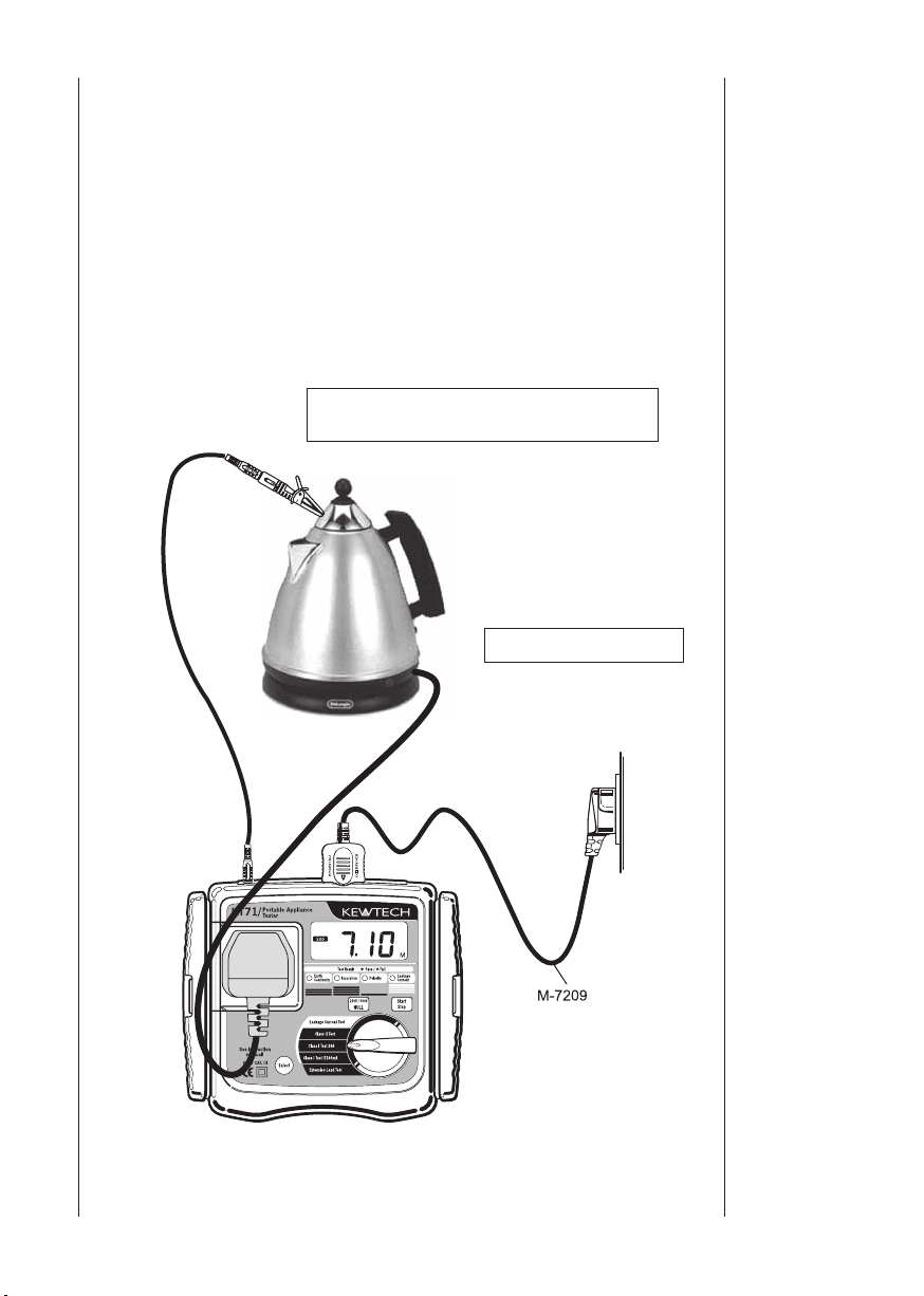
6.1 Class l Test (Common function for both IT200mA and 20A)
The purpose of the test carried out for Class I appliances is to check
the resistance of earth continuity from exposed metal parts and the
plug is below a certain level and the insulation resistance between live
and neutral connected together and earth is below 1M
protective conductor resistance and insulation resistance tests on an
appliance, connect the mains plug of the appliance to the test socket (1)
described in clause 3.4 Instrument layout and the PE probe to terminal
(5).
Use the following setups, depending upon the type of appliance.
Connect to exposed metal parts but not
rotating parts or heating elements.
Ω
. To conduct
Switch ON the power.
6. Measuring
method
Fig.12
Page 20

18
Start
RPE ≦ 0.1Ω ?
LnE ≧ 1MΩ ?
Is the appliance
switched on?
No
Ye
s
Ye
s
Ye
s
No
No
(1). Protective conductor resistance.
Lights up in red
Lights up in red
Lights up in green
Lights up in green
”no” →“Con”→”value”
will be repeated on
the LCD.
(See note 1 below)
”no” →“LnE”→”value”
will be repeated on the
LCD.
”oFF” →“ ? ” is displayed
alternately on the LCD.
Can proceed to the next
step by pressing the Start
switch again even if the
result was a fail
Re-start
Re-start
(2).Appliance switch test
(3). Insulation resistance between L/N and PE.
Value (1). and (3). will be alternately displayed on LCD
PASS
Measuring
Class I Test Flowchart
method
Note 1: The IEE Code of Practice states that the maximum resistance
should be no greater than 0.1 Ohms + the resistance of the mains cable.
Therefore if the appliance has a long mains lead then the allowable
resistance can be higher than the pre-programmed 0.1
Ω
.
Page 21

19
CAUTION
● If the Appliance switch test fails, displayed by OFF and ?
appearing alternately on the LCD, and the appliance is actually
switched on there may be a direct short between L and N.
Suspend testing immediately.
● Follow the procedure described in 5.2.3 and undertake the Null
setting before a measurement.
● The crocodile clip must make good contact with the enclosure
of the appliance.
● When the terminal is open or the resistance value exceeds
measuring range, > mark (over range display) appears on the
LCD.
● Do not touch the appliance under test whilst testing is in
progress. Since a high voltage of 500V will be present and the
user may get an electrical shock.
6.2 Class I Test (Select the leakage current test) – common to both
IT200mA and 20A function
Turning the rotary dial to either Class I Test whilst the
is being pressed down initiates a leakage current test instead of the
Insulation resistance test.
When selecting the leakage current test, exposed metal parts other than
the heating or movable parts must be clipped with Test Lead M-7208
since the appliance will switch on and activate. Pressing the
switch during the leakage current test stops the test immediately. To
restart the test, press the
has been stopped. Then (1) Protective conductor resistance will be
restarted. Fig 12 indicates how to connect the devices.
Refer to item 6.6 on details of Leakage Current Test
Start/Stop
switch again 2 sec after the test
Select switch
Start/Stop
Measuring
method
Page 22

20
Start
RPE ≦ 0.1Ω ?
LEA ≦ 3.5mA ?
No
Ye
s
Ye
s
No
(1). Protective conductor resistance.
Lights up in red
Lights up in red
Lights up in green
Lights up in green
”no” →“Con”→”value”
will be repeated on
the LCD.
(See note 1 below)
Stop the test and
”no” →“LEA”→”value”
will be repeated on the
LCD.
Standby until Start switch is pressed
again whilst indicating on the LCD.
Re-start
(2). Wait
(4). Power-on leakage current test.
(3). Appliance load current test.
Value of (1),(3) and (4) will be alternately displayed on the LCD.
5sec Measures load current of the instrument.
10sec Measures leakage current of the appliance.
LCD indicates during the measurement.
PASS
Measuring
Class I Test (Select the Leakage Current Test) Flowchart
method
Note 1: The IEE Code of Practice states that the maximum resistance
should be no greater than 0.1 Ohms + the resistance of the mains cable.
Therefore if the appliance has a long mains lead then the allowable
resistance can be higher than the pre-programmed 0.1
Ω
.
Page 23

21
CAUTION
● When the terminal is open or the resistance value, load current
and leakage current exceeds the measuring range, > (over
range display) appears on the LCD.
● If the test is stopped, a message StP appears on the LCD and
values of leakage current are not displayed.
WARNING
● W h en co nd u ct i ng a lea k ag e t e s t t h e ap p li a n ce wi l l
automatically power on and will operate in its normal manner.
It is imperative that the appliance is secured safely before the
test is carried out. Extra care needs to taken with appliances
which have heating elements and rotating parts.
● Firmly insert the plug of the appliance to the socket of the
KT71. Plugs may get hot if leakage current test is performed
with improper connection.
● Do not connect/remove the plugs during leakage current test.
It may cause a reading error. Do not use the instrument on the
device which has a power consumption of 3kVA or more.
6.3 Class ll Test
The Class ll appliances have the indication of DOUBLE INSULATION
or the
re s ista n ce of the appli ances is with i n the range define d i n the
standards.
symbol. The Class ll insulation test is to check the insulation
Measuring
method
Page 24

22
Start
Is the appliance
switched on?
LnE ≧ 2MΩ ?
No
Ye
s
Ye
s
No
(1). Appliance switch test
Lights up in red
Lights up in green
When the resistance
between L-N is about
100kΩ or more ”oFF” →
“ ? ” is displayed
alternately on the LCD.
”no” →“LnE”→ ”value”
will be repeated on the
LCD.
Re-start
(2). Insulation resistance between L/N and PE.
Va
lue of (2). will be displayed on the LCD.
PASS
Measuring
method
Connect to exposed
metal parts but not
rotating parts or
heating elements.
Class ll Test Flowchart
Switch ON the power.
Fig.13
Page 25

23
CAUTION
● If the Appliance switch test fails, displayed by OFF and ?
appearing alternately on the LCD, and the appliance is actually
switched on there may be a direct short between L and N.
Suspend testing immediately.
● When the terminal is open or the resistance value exceeds the
measuring range, > mark (over range display) appears on
the LCD.
● Do not touch the appliance under test whilst testing is in
progress. Since a high voltage of 500V will be present and the
user may get an electrical shock.
6.4 Class ll Test (Select the leakage current test)
When turning the rotary dial to the Class II Test whilst pressing the
Select switch, power-on leakage current test will be carried out instead
of Insulation resistance test. When leakage current test is chosen,
the appliance will switch on and operate in its normal manner. When
connecting the test lead do not clip a metal a rotating part or heating
element with the Test Lead M-7208.
Refer to item 6.6 on details of Leakage Current Test
Measuring
method
Page 26

24
Start
LEA ≦ 0.25mA ?
Yes
No
(1). Wait
Lights up in red
Lights up in green
Standby until the Start switch is
pressed again whilst the flashing
icon is indicated.
Stop the test and
”no” → “LEA” → ”value”
will be repeated on the
LCD.
(2). Appliance load current test.
(3). Power-on leakage current test.
Value of (2) and (3) will be displayed on the LCD.
PA
SS
5sec Measures load current of the instrument.
10sec Measures leakage current of the
appliance. LCD indicates
during the measurement.
Measuring
Class II Test (Select the Leakage Current Test) Flowchart
method
● When load current exceeds 15A or leakage current exceeds
20mA, > (over range display) appears on the LCD.
● If the test is stopped, a message StP appears on the LCD and
● W h en co nd u ct i ng a lea k ag e t e s t t h e ap p li a n ce wi l l
values of leakage current are not displayed.
automatically power on and will operate in its normal manner.
It is imperative that the appliance is secured safely before the
test is carried out. Extra care needs to taken with appliances
which have heating elements and rotating parts.
● Firmly insert the plug of the appliance to the socket of the
KT71. Plugs may get hot if leakage current test is performed
with improper connection.
● Do not connect/remove the plugs during leakage current test.
It may cause a reading error. Do not use the instrument on the
device which has a power consumption of 3kVA or more.
CAUTION
WARNING
Page 27

25
6.5 Extension Leads Test
M-7209
This test is for extension leads, and checks for;
● Protective conductor resistance between accessible conductive
parts and connection of protective earth.
●
Insulation resistance between L/N and PE.
●
Polarity check of the Live and Neutral terminal of plug and socket.
Test procedure and the connection are as follows.
Extension
leads adapter
KAMP S (UK)
Measuring
method
Fig.14
Page 28

26
Measuring
Start
RPE ≦ 0.1Ω ?
L-L & N-N ≦10Ω?
LnE ≧ 1MΩ?
No
Ye
s
Ye
s
Ye
s
No
No
(1). Protective conductor resistance test.
Lights up in red
Lights up in red
Lights up in red
Lights up in green
Lights up in green
”no” → “Con” → ”value”
will be repeated on the
LCD.
(See note 1 below)
”no” → “L-L” → ”value”
or ”no” → ”n-n” → ”value”
will be repeated on the
LCD.
”no” →“LnE”→”value”
will be repeated on the
LCD.
Re-start
Re-start
(2). Insulation resistance test between L/N and PE.
(3). Polarity test between L-L and N-N.
Value of (1) and (2) will be alternately displayed on LCD.
PA
SS
Extension Leads Test Flowchart
method
Note 1: The IEE Code of Practice states that the maximum resistance
should be no greater than 0.1 Ohms + the resistance of the mains cable.
Therefore if the appliance has a long mains lead then the allowable
resistance can be higher than the pre-programmed 0.1
Ω
.
Page 29

27
CAUTION
● Follow the procedure described in 5.2.3 and do Null setting
before a measurement, but use the short KAMP S lead instead
of the M-7208 tes t lead, by plugging the KAMP S. Into the
Extension Lead Adaptor terminal and the UK socket on the
front of the unit.
● When the terminal is open or the resistance value exceeds the
measuring range, > (over range display) appears on the
LCD.
● Do not touch the device under test whils t te s ting is in
progress. Since a high voltage of 500V will be present, the user
may get an electrical shock.
6.6 Leakage Current Test
This function is to conduct the leakage current test separately at mains
voltage, the appliance will be automatically switched on and power up in
its normal manner.
The leakage current test, measures load current of the instrument for
about 5 seconds, then measures leakage current for about 10 seconds
and both measured results are displayed. The KT71 can measure up to
20mA although the threshold value is 0.75mA in this function.
Measuring
method
●
Set the function switch to Leakage Current Test position.
●
Refer to the Fig12 or Fig13 for connection of an appliance.
● After set up is done, press the
flashing icon on the LCD at standby mode.)
● Check the switch of the appliance is ON.
● Press
● The appliance will operate for 15 seconds and indicate the final
Start/Stop
values (value after 15 sec.) of load current and the maximum value
of leakage current.
switch again.
Start/Stop
switch. (Indicated by the
Page 30

28
Start
LEA ≦ 0.75mA ?
Ye
s
No
(1). Wait
Lights up in red
Lights up in green
Standby until Start switch is pressed
again whilst the flashing icon is
indicated.
Stop the test and
”no” → “LEA” → ”value”
will be repeated on the
LCD.
(2). Appliance load current test.
(3). Power-on leakage current test.
Value of (2) and (3) will be displayed on the LCD.
PA
SS
5sec Measures load current of the instrument.
10sec Measures leakage current of the
appliance. LCD indicates
during the measurement.
Measuring
method
Leakage Current Measurement Flowchart
-
Remarks
-
Stopping the Test
1) Emergency stop and restart manually for power-on leakage current
test:
In order to stop testing the leakage current whilst measuring, press
Start/Stop
2 seconds or more from when the test has been stopped. The test will
. To start a test again, press
restart.
2) Auto stop of power-on leakage current test:
The ins trument stops measur ing immediatel y when load curre nt
exceeds 15A or leakage current exceeds 20mA (but more than 3.5mA
in Class I test function and more than 0.25mA in Class II test function).
Start/Stop
again after about
Page 31

29
WARNING
● W h en co nd u ct i ng a lea k ag e t e s t t h e ap p li a n ce wi l l
automatically power on and will operate in its normal manner.
It is imperative that the appliance is secured safely before the
test is carried out. Extra care needs to taken with appliances
which have heating elements and rotating parts.
● Firmly insert the plug of the appliance to the socket of the
KT71. Plugs may get hot if leakage current test is performed
with improper connection.
● Do not connect/remove the plugs during leakage current test.
It may cause a reading error. Do not use the instrument on the
device which has a power consumption of 3kVA or more.
Measuring
method
Wh en the f use blows d urin g use, ple ase repla ce with a n ew one
according to below procedure.
Fig.15
(1) Use a flat head screwdriver and turn about 45º to the left and remove
the fuse cap and fuse.
(2) Remove the fuse from the fuse cap and replace it with new one.
(3) Refitting is the reverse procedure.
7. Fuse
replacement
Page 32

Fuse
replacement
WARNING
● Remove mains cord from the instrument before replacing the
fuse.
● Thi s is the only use r replace able f use. N ever a ttem pt to
perform any other repairs.
CAUTION
● Please use the specified fuse (Fast acting type ceramic fuse:
600V/10A - Φ6.3x32mm).
8. Case and
strap
assembly
9. Maintenance
The strap and test lead case can be attached to the instrument as below.
Pass the strap belt down through the side panel of the main body from the
top, and up through the slots of the test lead case from the bottom. (Fig.
16).
Pass the strap through the buckle, adjust the strap for length and secure.
Fig.16
Use a very slightly damp cloth for cleaning the instrument. Do not use
abrasives or solvents.
30
Page 33

Kewtech Corporation Ltd.
Midas House, Unit 2b
Stones Courtyard
High Street, Chesham
Buckinghamshire HP
www.kewtechcorp.com
5 IDE
31
Page 34

Tel:01494 792212
92-1890A 07-01
 Loading...