


15. Back Light .................................................................................. 47
16. Memory Function ........................................................................ 48
16.1 How to save the data ......................................................... 48
16.2 Recall the saved data ......................................................... 50
16.3 Delete the saved data .
16.4 Transfer the stored data to PC ............................................ 53
17. General ...................................................................................... 54
18. Battery replacement .................................................................... 55
19. Fuse replacement ........................................................................
20. Servicing and Calibration ............................................................. 56
21. Pat test with the Pat adapter 1 ..................................................... 57
22. Zs tables .................................................................................... 58
23. Case and strap assembly .............................................................
The KT65DL incorporates Anti Trip Technology (ATT) which electronically
bypasses RCDs when performing loop impedance tests. This saves time and
money by not having to take the RCD out of the circuit during testing and is a
safer procedure to follow.
With the ATT function enabled, a test of 15mA or less is applied between
line & earth. It enables l
rated at 30mA and above.
Please read this instruction manual carefully before using this equipment.
oop impedance measurements without tripping RCDs
....................................................... 51
55
60
Contents

1
1 Safe Testing
Electricity is dangerous and can cause injury and death. Always treat
it with the greatest of respect and care. If you are not quite sure how
to proceed, stop and take advice from a qualified person.
1 This instrument must only be used by a competent and trained person
and operated in strict accordance with the instructions. Kewtech will
not accept liability for any damage or injury caused by misu
c
ompliance with the instructions or with the safety procedures.
2 It is essential to read and to understand the safety rules contained
in these instructions. They must always be observed when using the
instrument.
3 This instrument is designed to work in distribution systems where the line
to earth has a maximum voltage of 300V 50/60Hz and for some ranges
where line to line has a maximum
B
e sure to use it within this rated voltage.
For use in the continuity testing and insulation testing modes this
instrument must be used ONLY on circuits which are de-energized.
4 When conducting tests do not touch any exposed metalwork associated
with the installation. Such metalwork may become live for the duration of
the test.
5 Never open the instrument case (except
replacement and in this case disconnect all leads first) because
dangerous voltages are present. Only fully trained and competent
electrical engineers should open the case. If a fault develops, return the
instrument to Kewtech for inspection and repair.
6 If the overheat symbol appears in the display disconnect the instrument
from the mains supply and allow to cool down.
abnormal conditions of any sort are noted (such as a faulty display,
7 If
unexpected readings, broken case, cracked test leads, etc) do not use
the tester and return it to Kewtech for repair.
8 For safety reasons only use accessories (test leads, probes, fuses,
cases, etc) designed to be used with this instrument and recommended
by Kewtech. The use of other accessories is prohibited as they are
y to have the corre
unlikel
9 When testing, always be sure to keep your fingers behind the finger
guards on the test leads.
10 During testing it is possible that there may be a momentary degradation
of the reading due to the presence of excessive transients or discharges
on the electrical system under test. Should this be observed, the test
must be repeated to obtain a correct reading.
Kewtech.
ct safety features.
voltage of 500V 50/60Hz.
for fuse and battery
If in doubt, contact
se or non-

2
11 Do not operate the function selector whilst the instrument is connected to
a circuit. If, for example, the instrument has just completed a continuity
test and an insulation test is to follow, disconnect the test leads from the
circuit before moving the selector switch.
12 Do not rotate rotary switch when test button is depressed. If the function
switch is inadvertently moved to a new function
depressed or in lock-down position the test in progress will be halted.
13 Always check the test lead resistance before carrying out tests. This
ensures the leads are ok before taking measurements. The resistance
of leads and/or crocodile clips may be significant when measuring
low resistances. If crocodile clips can be avoided for low resistance
measurements, this will red
14 When carrying out Insulation Resistance tests, always release the test
button and wait for charged capacitances to totally discharge before
removing the test leads from the test circuit.
uce the erro
r due to lead accessories
when the test button is
Safe Testing
3
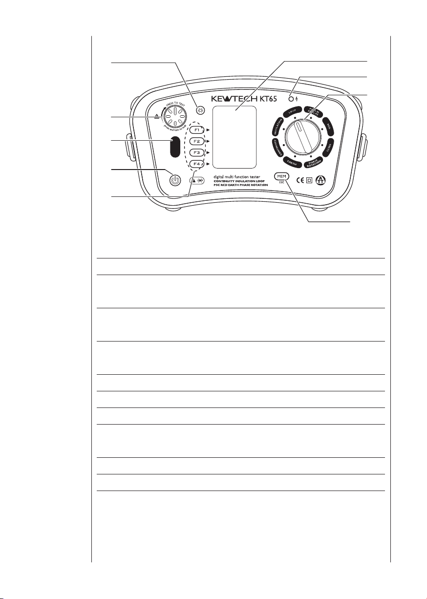
2 Instrument
(6)
(1)
(3)
(4)
(5)
(7)
(8)
(2)
(9)
layout
Fig. 1
Name Operation
(1) Back Light Button
(2) Test Button
(3) Touch Pad
(4) Power Switch Power Switch
(5) Function Switch Function setting (F1 ~ F4)
(6) Display (LCD) Dot Matrix LCD 160(W)X240(H)
(7) Insulation resistance LED
(8) Rotary Switch Selects measurement functions.
(9) MEM (ESC) Button Activates Memory Function, or ESC Key
Switches on/of f the Backlight of the
Display(LCD)
Starts measurements. (press and rotate
for lock down feature)
Checks the electrical potential at the PE
terminal
Aler ts that the test voltage is
output
being

4
Input Terminal
(1)
(2)
(3)
(4)
Instrument
layout
Fig. 2
Function Terminal
Terminal Names for :
INSULATION,
CONTINUITY
(1)
LOOP,
PFC/PSC,
RCD,
VOLTS
Terminal Name for
(2)
PHASE ROTATION
Te r mi n al Na m e fo r
(3)
EARTH
(4) Optical Adapter Co
L : Line
PE : Protective Earth
N : Neutral (for LOOP,PSC/PFC, RCD)
L1 : Line1
L2 : Line2
L3 : Line3
H(C) : Terminal for auxiliary earth spike
E : Terminal for the earth electrode
S(P) : Terminal for auxiliary earth spike
(current)
(potential)
mmunication port
for Model8212USB

5
Accessories
Blue(Neutral)
Brown(Line)
Green(Protective Earth)
Blue(Neutral or L3)
Green(Protective Earth
or L2)
Brown(Line or L1)
Yellow S(P)10m
Green E 5m
Red H(C) 20m
Auxiliary Earth Spikes x2
3
1. Main Test Lead (KAMP12)
Fig. 3
2. Remote Test Lead (ACC064SP)
Fig. 4
3. Distribution Board Test Lead (ACC065)
g. 5
Fi
4. Test Lead Carry pouch・・・x1
5. Carrying Bag・・・x1
6. Instruction Manual・・・x1
7. Shoulder Strap・・・x1
8. Buckle・・・x2
9. Battery・・・x8
10. Optional Accessory
PAT ADAPTER - See Page57
・
Earth Tests Lead(Model7228) and Auxiliary Earth Spikes
・
Fig. 7
Fig. 6
Model8212USB with PC Software KEW Report.
・
Fig. 8

6
The KT65DL Multi-Function tester performs eight functions in one instrument.
1 Continuity
2 Insulation resistance
3 Loop impedance
4 Prospective short circuit current
5 RCD
6 Voltage
7 Phase rotation
8 Earth resistance
Continuity function has the following features:
Live circuit warning Live Circuit warning on the display.
Fuse Protection Continuity Function has a fuse protection function
to prevent a
Wi th this func tion, a fuse ra rely bl ow while
measuring continuity on live conductors.
Continuity Null Allows automat i c sub t r a ction of test lead
resistance from continuity measurements.
Continuity 2Ω Buzzer Buzzer sounds at 2Ω or le ss at Conti nuity
function. (Switchable on or off)
Insulation function has the following features:
Live circuit warning Live Circuit wa
Auto discharge Electric charges stored in capacitive circuits
are discharged automatically after testing by
releasing the test button.
Insulation Resistance LED LED lights up while making measurements at
Insulation function and alerts that test voltage is
being output.
fuse blow at live working.
rning on the display.
4 Features
Loop impedance, PSC/PFC and RCD testing functions have the following
features:
ymbols indicate if the wiring of the
Wiring check Three Wirin
circuit under test is correct.
Over temperature protection
Phase angle selector The test can be selected from either the positive
Detects overheating of the internal resistor (used
for LOOP and PSC/PFC tests) and of the current
control MOS FET (used for RCD tests) displaying
a wa rning symbol and automatic ally halting
further measurements.
(0 ° ) or from th
voltage. This selector is used in the RCD mode to
g s
e n
egative (180 ° ) half cycle of

7
Features
obtain the maximum trip time of an RCD for the
test selected.
UL value selector Select UL (limit of contact voltage) 25V or 50V.
Where Uc (contact voltage) exceeds UL value at
RCD testing, Uc > UL will be displayed without
starting the measurement.
ALL testing functions have the following
Touch Pad Gives an alert, when touching the Touch Pad,
while the PE terminal is connected to Line by
take.
mis
Memory Function Save the measured data in the internal memory.
The da t a can be ed i t e d on a PC by us i n g
Communication Adapter Model8212USB and PC
Software KEW Report.
Auto power off Automatically switches the instrument off after
a period of approxim ately 10 mi nutes. Th e
Auto power off mode can only be cancelled by
switching the instrument on again.

8
5.1 Measurement Specification
Continuity
5 Specification
Open Circuit
Voltage (DC)
5V±20%(*1)
2Ω Buzzer : Buzzer sounds when measured resistance is 2Ω or less.
2Ω Buzzer Accuracy : 2Ω±0.4Ω
(*1) Voltages are output when measurement resistance is under 2100 ohm.
Insulation Resistance
Open Circuit
Voltage (DC)
250V+25% -0%
500V+25% -0%
1000V+20% -0%
Short Circuit
Current
Greater than
200mA
Rated Current Range Accuracy
1mA or greater
@ 250kΩ
1mA or greater
@ 500kΩ
1mA or greater
@ 1MΩ
Range Accuracy
20/200/2000Ω
Auto-Ranging
20/200MΩ
Auto-Ranging
20/200/1000MΩ
Auto-Ranging
20/200/2000MΩ
Auto-Ranging
0~0.19Ω ±0.1Ω
0.2~2000Ω
0~19.99MΩ:
±(2%rdg+6dgt)
20~200MΩ:
±(5%rdg+6dgt)
0~199.9MΩ:
±(2%rdg+6dgt)
200~1000MΩ:
±(5%rdg+6dgt)
0~199.9MΩ:
±(2%rdg+6dgt)
200~2000MΩ:
±(5%rdg+6dgt)
±(2%rdg+8dgt)

9
Specification
Loop Impedance
Function
0.01
ΩRes
L-PE
0.001
ΩRes
L-PE
(ATT)
L-N / L-L
*2 : at 230V
*3 : 230V+10%-15%
*4: 50V~100V
*5: voltages except for *3 and *4
Rated
Voltage
50~260V
50/60Hz
230V
+10%-15%
50/60Hz
100~260V
50/60Hz
50/60Hz
L-N:50~300V
L-L:300~500V
Nominal Test Current
at 0Ω External Loop:
Magnitude/Duration(*2)
20Ω: 6A/20ms
200Ω: 2A/20ms
2000Ω:
15mA/500ms
2Ω: 6A/90ms
L-N: 6A/60ms
N-PE: 10mA/
approx. 5s
20Ω: 6A/20ms
Range Accuracy
20/200/2000Ω
Auto-Ranging
2Ω
20/200/2000Ω
Auto-Ranging
(L-N < 20Ω)
20Ω
±(3%rdg+4dgt) *3
±(5%rdg+15dgt) *4
±(3%rdg+8dgt) *5
±(3%rdg+35mΩ)
±(3%rdg+6dgt) *3
±(3%rdg+8dgt) *4
±(3%rdg+4dgt) *3
±(5%rdg+15dgt) *4
±(3%rdg+8dgt) *5
PSC (L-N/L-L) / PFC (L-PE)
Nominal Test Current
at 0Ω External Loop:
Magnitude/Duration(*6)
Function
PSC
PFC
PFC (ATT)
*6: at 230V
Rated
Voltage
50~500V
50/60Hz
50~260V
50/60Hz
100~260V
50/60Hz
6A/20ms
6A/20ms
2A/20ms
15mA/500ms
L-N: 6A/60ms
N-PE: 10mA/
approx. 5s
Range Accuracy
2000A/20kA
Auto-Ranging
PSC/PFC
accuracy is
derived from
measured loop
impedance
specification and
measured voltage
specification

10
RCD
Accuracy
Function Rated Voltage
X1/2
X1 +2%~+8% 0%~+10%
X5 +2%~+8% 0%~+10%
Ramp(◢) ±4% ± 10%
Auto
RCD Trip Current Duration
Function Type
Trip
Current
Duration
(ms)
230V+10%-15%
50/60Hz
Depending on the accuracy at each function.
Measurement sequence:
X1/2 0°→X1/2 180°→X1 0°→X1 180°→X5 0°→X5 180°
Measurements with x5 are not carried out for RCDs with nominal
current of 100mA or more.
AC 2000 2000 2000 2000 2000 2000
G
X1/2
X1
X5
Ramp
(◢)
A 2000 2000 2000 2000 2000 n.a
AC 2000 2000 2000 2000 2000 n.a
S
A 2000 2000 2000 2000 2000 n.a
AC 550 550 550 550 550 550
G
A 550 550 550 550 550 n.a
AC 1000 1000 1000 1000 1000 n.a
S
A 1000 1000 1000 1000 1000 n.a
AC 410 410 410 n.a n.a n.a
G
A 410 410 410 n.a n.a n.a
AC 410 410 410 n.a n.a n.a
S
A 410 410 410 n.a n.a n.a
AC
G
A n.a
AC
S
A n.a
Trip Current
AC Type A Type
-8%~-2% -10%~0%
RCD Trip Current Duration
10 30 100 300 500 1000
Goes up by 10% from 20% to 110%
00ms×10 times
3
Goes up by 10% from 20% to 110%
500ms×10 times
Trip Time
±(1%rdg+3dgt)
.a
n
n.a
Specification
Earth
Measuring
Frequency
825Hz
Range Accuracy
20/200/2000Ω
Auto-Ranging
20Ω range : ±(3%rdg+0.1Ω)
200/2000Ω range : ±(3%rdg+3dgt)
(Auxiliary earth resistance 100±5%)

11
Specification
PHASE ROTATION
Rated Voltage
Remarks
50-500V
50/60Hz
Volts
Function Rated voltage Measuring Range Accuracy
Frequency
Possible number of tests with fresh batteries.
Continuity : Approx. 2000 times min. at load 1Ω
Insulation Resistance : Approx. 1000 times min. at load 1MΩ (1000V)
LOOP/PFC/PSC : Approx. 1000 times min. (ATT)
RCD : Approx. 2000 times min. (G-AC X1 30mA)
EARTH : Approx. 10
OLT/PHASE ROTATION : Approx. 50H
V
Reference Conditions
Correct phase sequence: are displayed 1.2.3 and
Reversed phase sequence: are displayed 3.2.1 and
Volts
Ambient temperature 23±5℃
Relative humidity 45% to 75%
25~500V
45~65Hz
25~500V
45~65Hz
25~500V ±(2%rdg+4dgt)
45~65Hz ±(0.5%rdg+2dgt)
00 times min. at load 10Ω
mark
mark
Nominal system voltage and
frequency
Altitude Less than 2000m
5.2 Operating error
Continuity (EN61557-4)
Operating range compliant with
EN61557-4 operating error
0.20~1999MΩ ±30%
The influencing variations used for calculating the operating error are denoted
as follows;
Temperature : 0℃ and 35℃
Supply voltage : 8V to 13.8V
230V, 50Hz
Maximum percentage
operating error

12
Insulation Resistance(EN61557-2)
Volt
250V 0.25~199.9MΩ
1000V 1.00~1999MΩ
The influencing variations used for calculating the operating error are denoted
as follows;
Temperature : 0℃ and 35 ℃
Supply voltage : 8V to 13.8V
Loop Impedance(EN61557-3)
Volt
L-PE
L-N 0.40~19.99Ω
The influencing variations used for calculating the operating error are denoted
as follows;
Temperature : 0 ℃ and 35 ℃
Phase angle : At a phase angle 0° to 18°
System frequency : 49.5Hz to 50.5Hz
System voltage : 230V+10%-15%
Supply voltage : 8V to 13.
H
armonics :
D.C quantity : 0.5% of the nominal voltage
Operating range compliant with
EN61557-2 operating error
Operating range compliant with
EN61557-3 operating error
0.40~1999Ω
(0.001ΩRes:0.400~1.999Ω)
8V
5% of 3rd harmonic at 0° phase angle, 5% of 5th harmonic
at 180° phase angle, 5% of 7th harmonic at 0° phase angle
Maximum percentage
operating error
±30%500V 0.50~999MΩ
Maximum percentage
operating error
±30%
Specification
RCD(EN61557-6)
Function Operating error of trip current
X1/2 -10%~0%
X1, X5 0%~+10%
Ramp -10%~+10%
The influencing variations used for calculating the operating error are denoted
as follows;
Temperature : 0 ℃ and 35 ℃
Earth electrode Resistance (shall not exceed below) :
IΔn (mA)
10 2000 2000
30 600 600
100 200 200
300 130 65
500 80 40
1000 40 20
System voltage : 230V+10%-15%
Supply voltage : 8V to 13.8V
Earth electrode resistance (Ω max.)
UL50V UL25V
Table.1

13
Specification
Earth Resistance (EN61557-5)
Operating range compliant with EN61557-5
operating error
5.00~1999Ω ±30%
The influencing variations used for calculating the operating error are denoted
as follows;
Temperature : 0 ℃ and 35℃
Series interference voltage : 3V
Resistance of the probes and auxiliary
earth electrode resistance : 100 x RA, 50kΩ or less
Supply voltage : 8V to 13.8V
5.3 General specification
ment dimensions 2
Instru
Instrument weight:- 1350g (including batteries.)
Reference conditions Specifications are based on the following
1. Ambient temperature: 23±5° C:
2. Relative humidity 45% to 75%
3. Position: horizontal
4. AC power source 230V, 50Hz
5. DC power source: 12.0 V, ripple content 1%
6. Altitude up to 2000m, Indoor use
tery type E
Bat
Operating temperature and humidity.
0 to +40 ℃ , relative humidity 80% or less, no
Storage temperature and humidity
-20 to +60℃ , relative humidity 75% or less, no
Display Dot Matrix LCD 160(W) X 240(H) pixels.
Overload protection The continuity test circuit is protected by a
The insulation resistance test circuit is protected
35 X 136 X 114mm
conditions, except where otherwise stated:-
or less
ight LR6,AA or R6 batteries.
condensation
condensation.
0.5A/600 V fast acting (HRC) ceramic fuse
mounted in the batt
spare fuse is also stored.
by a resistor against 1000 V AC for 10 seconds.
Maximum percentage
operating error
ery compartment, where a
14
5.4 Applied standards
Instrument operating IEC/EN61557-1,2,3,4,5,6,7,10
Standard
Safety standard IEC/EN 61010-1(2001),
CATIII (300V) -Instrument
IEC/EN 61010-031(2008)
CATII (250V)-Test Lead KAMP12
CATIII (600V)-Test Lead ACC065
CATIII (1000V)-Test Lead ACC064SP
CATIII (300V)-Test Lead Model7228
Protection degree IEC 60529 (1989 + A1) IP40
EMC EN 61326
EN55022/24
Specification
This manual and product may use the foll
a
dopted from International Safety Standards;
CAT.III Measurement category CAT III applies to;
Primary electrical circuits of the equipment connected directly
to the distribution panel, and feeders from the distribution
panel to outlets.
Equipment protected throughout by DOUBLE INSULATION or
REINFORCED INSULATION;
Caution (refer to accompanying documents)
Caution, risk of electric shock
Protection against wrong connection is up to 500V
Earth Ground
owing symbols
15
Specification
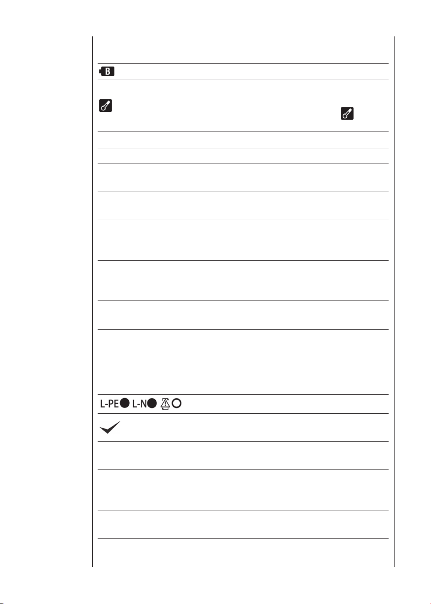
5.5 List of Display Message
Low battery warning
Tem p erat u re moni t o r f o r in t e r nal resistan c e ,
available at Loop, PSC/PFC & RCD function. Further
measurements are suspended until the
disappears.
Measuring Measurements in progress
Live Circuit Live circuit warning (Continuity / Insulation Function)
PE Hi V
L-N >20Ω
Noise
N - PE Hi V
Uc > UL
no
Caution : Presence of 100V or more at PE terminal,
appears when touching the Touch Pad
Alert : Presence of 20Ω or more between Line Neutral at ATT measurement
Caution : Presence of noise in the circuit under test
during ATT measurement. ATT function should be
isabled to continue measurements.
d
Caution: Presence of high voltage between NEUTRAL
- EARTH during ATT measurement. ATT function
should be disabled to continue measurements.
Caution : Uc at RCD measurement is exceeding the
preset UL value (25 or 50V).
Error message : When on the RCD function, RCD
tripped before measuring RCD trip time. Selected
IΔn value may not be correct.
on the LOOP, PSC/PFC function, supply may
When
have been interrupted.
symbol
OK
NO
×
Hi, RS Hi
R
H
No 3-phase system
Wiring check for LOOP, PSC/PFC function
Appears when all results passed during the RCD Auto
Test function.
Appears when any results failed during the RCD Auto
Test function.
Appears when a Probe resistance of H terminal
(RH) or of S terminal (RS) at Earth measurement is
exceeded the measurable range.
Appears to indicate wrong connection at Phase
Rotation check.

16
Setting for following three parameters
1. Press the Config Button
(F4) when powering on
KT65. (Fig.9)
2. Then, Configuration
Screen (Fig.10) is
displayed.
KT65
TESTER
MULTI FUNCTION
Config
Push
Touch Pad :
UL :
OFF
Configuration
Back Light :
ON
50V
ESC
▲ UL value・・・・・・・・Selects a UL value for RCD function
▲ Touch Pad・・・・・・Enables / disables Touch Pad function
▲ Back Light・・・・・・Selects Backlight ON / OFF. When ON is selected, the
Backlight automatically turns on at powering on the instrument.
Setting method
Fig. 9 Fig. 10
6 Configuration
3. Press the F1 – F3 Button to change following setting.
Parameter Selection Initial value
F1 UL value 25V, 50V 50V
F2 Touch Pad ON, OFF ON
F3 Back Light ON, OFF OFF
4. Press the ESC Button (F4) when setting change is completed, and return to
the normal screen.
17
7 Continuity
NULL OFF
PAT OFF
ON
Ω
Brown
(Red)
Green
Warning: Ensure that circuits to be tested are not live.
Disconnect the instrument from the circuit under test before operating
the function switch.
To select the low resistance range select CONTINUITY.
7.1 Test Procedure
The object of continuity testing is to measure only the resistance of the parts
of the wiring system under test. This measurement should not include the
s u
resistance of any test lead
sed. The resistance of the test leads needs to
be subtracted from any continuity measurement. The KT65DL is provided with
a continuity null feature which allows automatic compensation for any test
lead resistance.
You should only use the test leads supplied with the instrument.
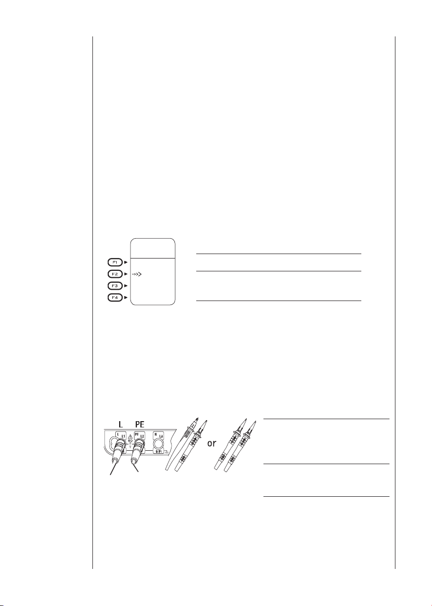
Operation of Function Switch
F1 Switches on / off NULL function
F2 Switches on / off 2Ω buzzer
PAT mode setting.
F3
(PAT OFF, CL1 0.1Ω, CL1 0.3Ω)
Fig. 11
F4 N/A
Proceed as follows:1 Select the continuity test by rotating the Rotary switch.
2 Press F3 switch to select PAT mode setting.
3 Insert the Test Leads to the L and PE terminal on KT65DL respectively as
shown in Fig.12.
L terminal
Brown cord of ACC065, or
ACC064SP Remote Test Lead
PE terminal
Green cord of ACC065
Fig. 12
4 Connect the ends of the test leads firmly together (see Fig.13) and press
and lock down the test button. The value of the lead resistance will be
displayed.
18
NULL
ON
Ω
Measuring
NULL
ON
Ω
Measuring
PAT OFF
Fig. 13
5 Press the Continuity Null (F1) button, this will null out the lead resistance and
the indicated reading should go to zero.
6 Release the test button. Press the test button and ensure the display reads
zero before proceeding. While using the Continuity null function, NULL
is displayed on the LCD as indicated in Fig.13. The null value will be stored
even if the instrument is powered off. This memorised null value can be
cancelled by disconnecting the test leads and pushing the Continuity Null
button (F1) with the test button pressed or locked. When this is cancelled
you will know because NULL OFF is displayed on the LCD.
CAUTION - before taking any measurements
always check the leads have
been zeroed.
7 Connect the test leads to the circuit whose resistance is required (see
Fig.14 for a typical connection arrangement), having first made sure that
the circuit is not live. Note that Live Circuit warning will be displayed on
the LCD if the circuit is live - but check first anyway!
8 Press the test button and read the circuit resistance from the display. Th
re
ading will have the test lead resistance already subtracted if the Continuity
null function has been used.
9 Note that if the circuit resistance is greater than 20Ω the instrument will
autorange to the 200Ω, if it is greater than 200Ω it will autorange to the
2000Ω range.
Note: If the reading is greater than 2000Ω the overange symbol >
will remain displayed.
The results of measurements can be
adversely affected by impedances of
additional operating circuits connected in parallel or by transient currents.
Continuity
e

19
Continuity
Test at socket
between L and E
T
emporary lin
k
NULL
ON
Ω
NULL
ON
Ω
Measuring
PAT CL1 0.3
Ω
Pass or fail mark
Fig. 14
▲ If PAT mode Is selected, pass( ) or fail(X) mark is displayed during
measurement. Pass or fail mark is displayed on LCD according to the
following table.
MODE Measured Value Result
Less than 0.1 Ω Pass (
)
CL1 0.1 Ω
Over 0.1 Ω Fail (X)
Less than 0.3 Ω Pass (
)
CL1 0.3 Ω
Fig. 15
Over 0.3 Ω Fail (X)
) function
7.2 2Ω Buzzer (
Use F2 Button to enable / disable the 2Ω Buzzer. The Buzzer sounds when
measured resistance is 2Ω or less while this function is enabled. Buzzer does
not sound if it is disabled.

20
Warning: Ensure that circuits to be tested are not live.
Disconnect the instrument from the circuit under test before operating
the function switch.
To select the insulation resistance range select INSULATION.
8.1.1 The nature of insulation resistance
Live conductors are separated from each other and from earth by insulation,
which has a resistance which is high enough to ensure that the current
ween conductors and to earth is kept at an acceptably low level. Ideally
bet
insulation resistance is infinite and no current should be able to flow through
it. In practice, there will normally be a current between live conductors and
to earth, this is known as leakage current. This current is made up of three
components, which are:-
1. capacitive current
2. conduction current, and
3. surface leakage curre
8
.1.2 Capacitive Current
The insulation between conductors which have a potential difference between
them behaves as the dielectric of a capacitor, the conductors acting as
the capacitor plates. When a direct voltage is applied to the conductors, a
charging current will flow to the system which will die away to zero (usually
in less than a second) when the effective capacitor becomes charged. Thi
charge must be removed from the system at the end of the test, a function
which is automatically performed by the KT65DL. If an alternating voltage
is applied between the conductors, the system continuously charges and
discharges as the applied voltage alternates, so that there is a continuous
alternating leakage current flowing to the system.
nt.
8 Insulation
s
Fig. 16

21
Insulation
8.1.3 Conduction Current
Since the insulation resistance is not infinite, a small leakage current flows
through the insulation between conductors. Since Ohm's Law applies, the
leakage current can be calculated from
applied voltage (V)
Leakage current (μA) =
insulation resistance (MΩ)
Fig. 17
8.1.4 Surface Leakage Current
Where insulation is removed, for the connection of conductors and so on,
current will flow across the surfaces of the insulation between the bare
conductors.
the surfaces of the insulation between the conductors. If the surfaces are
clean and dry, the value of the leakage current will be very small. Where the
surfaces are wet and/or dirty, the surface leakage current may be significant.
If it becomes large enough, it may constitute a flashover between the
conductors.
Whether this happens depends o
on the applied voltage; this is why insulation tests are carried out at higher
voltages than those normally applying to the circuit concerned.
The amount of leakage current depends on the condition of
n t
he condition of the insulation surfaces and
Fig. 18
8.1.5 Total Leakage Current
The total leakage current is the sum of the capacitive, conduction and surface
leakage current described above. Each of the currents, and hence the
total leakage current, is affected b
conductor temperature, humidity and the applied voltage.
If the circuit has alternating voltage applied, the capacitive current (8.1.2) will
y factors such as ambient temperature,

22
always be present and can never be eliminated. This is why a direct voltage is
used for insulation resistance measurement, the leakage current in this case
quickly falling to zero so that it has no effect on the measurement. A high
voltage is used because this will often break down poor insulation and cause
flashover due to surface leakage (see 8.1.4), thus showing up potential faults
which would n
The insulation tester measures the applied voltage level and the leakage
current through the insulation. These values are internally calculated to give
the insulation resistance using the expression:-
Test voltage (V)
Insulation resistance (MΩ) =
Leakage current (μA)
As the capacitance of the system charges up, so the charging current falls to
zero and a steady insulation resistance reading indicates that the capacitance
of the syste
and will be dangerous if left with this charge. The KT65DL provides an
automatic path for discharging current as soon as the test button is released
to ensure that the circuit under test is safely discharged.
If the wiring system is wet and/or dirty, the surface leakage component of the
leakage current will be high, resulting in lo
the case of a very large electrical installation, all the individual circuit insulation
resistances are effectively in parallel and the overall resistance reading will be
low. The greater the number of circuits connected in parallel the lower will be
the overall insulation resistance.
ot be pre
s fully charged. The system is charged to the full test voltage,
m i
sent at lower levels.
w i
nsulation resistance reading. In
Insulation
8.2 Damage to Voltage-Sensitive Equipment
An increasing number of electronic-bas
connected to electrical installations. The solid state circuits in such equipment
are likely to be damaged by the application of the levels of voltage used
to test insulation resistance. To prevent such damage, it is important that
voltage-sensitive equipment is disconnected from the installation before the
test is carried out and reconnected again immediately after
which may need to be disconnected before the test include:-
▲ Electronic fluorescent starter switches
▲ Passive infra-red detectors (PIRs)
▲ Dimmer switches
▲ Touch switches
▲ Delay timers
▲ Power controllers
▲ Emergency lighting units
▲ Electronic RCDs
ed items of equipment are being
wards. The devices

23
Insulation
250V
PAT OFF
MΩ
Brown Green
(Red)
▲ Computers and printers
▲ Electronic point-of-sale terminals (cash registers)
▲ Any other device which includes electronic components.
8.3 Preparation for measurement
Before testing, always check the following:1 The low battery Indication is not displayed
2 There is no visually obvious damage to the tester or to the test leads
3 Test the continuity of the test leads by switching to continuity test
and
shorting out the lead ends. A high reading will indicate that there is a faulty
lead or that the fuse is blown.
4 Make sure the circuit to be tested is not live. Live Circuit warning is
displayed if the instrument is connected to a live circuit but test the circuit
as well!
Operation of Function Switch
F1 N/A
F2 N/A
PAT mode setting.
F3
(PAT OFF, CL1, CL2)
F4 Voltage setting
Fig. 19
8.4 Insulation resistance measurement
The KT65DL has three selectable test voltages of 250V, 500V and 1000V
DC.
1 Select INSULATION function with the Rotary switch.
2 Press the VOLT Switch (F4) and select desirable voltage range.
3 Press F3 switch to select PAT mode setting.
(In case of 1000V range, PAT mode is not selectable.)
t t
4 Inser
he Test Leads to the L and PE terminal on the KT65DL respectively
as shown in Fig.20.
L terminal
Brown cord of ACC065, or
ACC064SP Remote Test Lead
PE terminal
Green cord of ACC065
Fig. 20

24
5 Attach the test leads to the circuit or the appliance under test (see Figs 21
Note: insulation testing must only be undertaken on
1000V
MΩ
1
de-energised circuits
1000V
MΩ
& 22)
Fig. 21
6 If the Live Circuit warning is displayed on the LCD and/or the buzzer
sounds, do not press the test button but disconnect the instrument from
the circuit. Make the circuit dead before proceeding.
Insulation
Fig. 22
7 Press the test button, the display will show the insulation resistance of the
circuit or the appliance to which
8
Note that if the circuit resistance is greater than 20MΩ, the instrument will
the instrument is connected.
autorange to the 200MΩ range. If it is greater than 200MΩ at the 500V
or 1000V range, it will autorange to the 2000MΩ range.If it is greater than
200MΩ at the 500V range, it will autorange to the 1000MΩ range. If it is
greater than 200MΩ at the 1000V range, it will autorange to the 2000MΩ
range.
9
When testing is complete release the test button before disconnecting
the test leads from the circuit or from the appliance. This will ensure that
the charge built up by the circuit or the appliance during insulation test is

25
Insulation
250V
Measuring
PAT CL1
MΩ
CL1
>1M
Ω
Pass or fail mark
dissipated in the discharge circuit. In the discharging process, Live Circuit
warning will be displayed on the LCD and the live circuit warning buzzer will
sound.
▲ If PAT mode Is selected, pass(
) or fail(X) mark is displayed during
measurement. Pass or fail mark is displayed on LCD according to the
following table.
MODE Measured Value Result
Over 1M Ω Pass (
)
CL1
Less than 1MΩ Fail (X)
Over 2M Ω Pass (
)
CL2
Fig. 23
Less than 2MΩ Fail (X)
WARNING
Never touch the circuit, test lead tips or the appliance under test during
insulation testing because high voltages exist.
CAUTION
Never turn the Rotary switch whilst the test button is depressed as this may
damage the instrument.
Always release the test button first after
testing before removing the test
leads from the circuit. This is to ensure that charges stored in the circuit
capacitance have been totally discharged.
Note: If the reading measured greater than 2000MΩ (200MΩ at 250V
1000MΩ at 500V) the over range reading > will be displayed.

26
9.1 Principles of measurement of fault loop impedance and PFC
If an electrical installation is protected by over-current protective devices
including circuit breakers or fuses, the earth loop impedance should be
measured.
In the event of a fault the earth fault loop impedance should be low enough (and
the prospective fault current high enough) to allow automatic disconnection
of the electrical suppl
time interval. Every circuit must be tested to ensure that the earth fault loop
impedance value does not exceed that specified or appropriate for the overcurrent protective device installed in the circuit. The KT65DL takes a current
from the supply and measures the difference between the unloaded and
loaded supply voltages. From this differenc
loop resistance.
TT System
For a TT system the earth fault loop impedance is the sum of the following
impedances;
▲Impedance of the power transformer secondary winding.
▲ Impedance of the phase conductor resistance from the power transformer
to the location of the fault.
▲ The impedance of the protective conductor from the fault location to the
earth system.
▲Resistanc
▲Resistance of the power transformer earth system (Ro).
e of the local eart
y by the circuit protection device within a prescribed
e it is possible to calculate the
h system (R).
9 LOOP/PSC/PFC
The figure below shows (dotted line) the Fault loop impedance for TT systems.
Fig. 24

27
LOOP/PSC/PFC
According to the International Standard IEC 60364, for TT systems the
characteristics of the protective device and the circuit resistance shall fulfill
the following requirements:
Ra x Ia ≤ 50V Where:
Ra is the sum of the resistances in Ω of the local earth system and the
protective conductor for the exposed conductive parts.
50 is the maximum safety touch voltage limit (it can be 25V in particular
c
ases like construction sites, agricultural premises, etc.).
Ia is the current causing the automatic disconnection of the protective device
within the maximum disconnecting times required by IEC 60364-41:
- 200 ms for final circuits not exceeding 32A (at 230 / 400V AC)
- 1000 ms for distribution circuits and circuits over 32A (at 230 / 400V AC)
The compliance with the above rules shall be verified by:
1) Measurement of the resistance Ra of the local earth system by Loop tester
or Earth tester.
2) Verification of the characteristics and/or the effectiveness of the RCD
associated protective device.
Generally in TT systems, RCDs are used as a protective device and in this
case, Ia is the rated residual operating current IΔn. For instance in a TT
system protected by a RCD the max Ra values are:
Rated residual operating current IΔn
RA (with touch voltage of 50V) 1667 500 167 100 50 (Ω)
RA (with touch voltage of 25V) 833 250 83 50 25 (Ω)
Shown below is a practical example of verification of the protection by RCD in
a TT system according to the international Standard IEC 60364.
30 100 300 500 1000 (mA)

28
Ω
L - PE
L-PE
L-N
230
V
50.0Hz
ATT
:ON
!
Fig. 25
For this example the max permissible value is 1667 Ω (RCD =30mA and
contact voltage limit of 50 V). The instrument reads 12.74 Ω, thus the
condition RA ≤ 50/Ia is respected. However, considering that the RCD
is essential for protection, it must be tested (Please refer to RCD TESTS
section).
TN System
For TN systems the earth fault loop impedance is the sum of the following
impedances.
▲ Impedance of
the power transformer secondary winding.
▲ Impedance of the phase conductor from the power transformer to the
location of the fault.
▲ Impedance of the protective conductor from the fault location to the power
transformer.
LOOP/PSC/PFC
The figure below shows (dotted line) the Fault loop impedance for TN systems.
Fig. 26

29
LOOP/PSC/PFC
According to the International Standard IEC 60364, for TN system the
characteristics of the protective device and the circuit impedance shall fulfill
the following requirement:
Zs x Ia ≤ Uo Where:
Zs is the Fault loop impedance in ohm.
Uo is the nominal voltage between phase to earth (typically 230V AC for both
single phase and three phase circuits).
Ia is the current causing the automatic disconnec
within the maximum disconnecting times required by IEC 60364-41 that are:
- 400 ms for final circuits not exceeding 32A (at 230 / 400V AC)
- 5 s for distribution circuits and circuits over 32A (at 230 / 400V AC)
The compliance with the above rules shall be verified by:
1) Measurement of the fault loop impedance Zs by Loop tester.
2) Verification of the characterist
protective device. This verification shall be made:
- for circuit-breakers and fuses, by visual inspection (i.e. short time or
instantaneous tripping setting for circuit-breakers, current rating and type for
fuses);
- for RCDs, by visual inspection and test using RCD testers recommending
that the disconnecting times mentioned above are met (Please se
TEST section).
ics and/or the effectiveness of the associated
tion of the protective device
e RCD
For instance in a TN system with nominal mains voltage Uo = 230 V protected
by MCBs (Miniature Current Breakers) required by BSEN 60898, the max Zs
values could be:

30
Protected by BSEN 60898 MCB with Uo =230V
MCB
(Disconn.Time
0.4 and 5s)
MCB
(Disconn.
Time 0.4s)
MCB
(Disconn.
Time 5s)
B C D D
Current rating Zs (Ω) Zs (Ω) Zs (Ω) Zs (Ω)
6 7.28 3.64 1.82 3.64
10 4.37 2.19 1.09 2.19
16 2.73 1.37 0.68 1.37
20 2.19 1.09 0.55 1.09
25 1.75 0.87 0.44 0.87
32 1.37 0.68 0.34 0.68
40 1.09 0.55 0.27 0.55
50 0.87 0.44 0.22 0.44
63 0.69 0.35 0.17 0.35
Source: BS7671:2008 AMD 3:2015
The most comprehensive loop testers or Multifunction testers also have
the Prospective Fault current measurement. In this case, Prospective Fault
current measured values must be higher than the Ia of the protective device
concerned.
Below is a practical example of verifi cation of the protection by MCB in a TN
system according to the International Standard IEC 60364.
LOOP/PSC/PFC
Fig. 27

31
LOOP/PSC/PFC
PSC
A
230
V
L-N
50.0Hz
L-PE
L-N
!
Maximum value of Zs (in the table above) for this example is 2.73 Ω (MCB
16A, characteristic B).
The inst rument rea ds 1.14 Ω(or 202 A on Fault current range) and
consequently the condition Zs x Ia ≤ Uo is met.
In fact the Zs of 1.14 Ω is less than 2.73 Ω.
In other words, in case of a fault between phase and earth, the wall socket
tested in this example is protected because the MCB will trip within th
d
isconnection time required.
9.2 Principles of the measurement of line impedance and PSC
The method for measuring Line – neutral impedance and line-line impedance
is exactly the same as for earth fault loop impedance measurement with the
exception that the measurement is carried out between line and neutral or
line and line.
e
Prospective short circuit or fault current at any point within an electrica
installation is the current that would flow in the circuit if no circuit protection
operated and a complete (very low impedance) short circuit occurred.
The value of this fault current is determined by the supply voltage and the
impedance of the path taken by the fault current. Measurement of prospective
short circuit current can be used to check that the protective devices within
the system will
operate within safety limits and in accordance with the safe
design of the installation. The breaking current capacity of any installed
protective device should be always higher than the prospective short circuit
current.
l
Fig. 28

32
9.3. Operating instructions for LOOP and PSC/PFC
L-PE
Ω
ATT : ON
230V
50.0Hz
L-PE
L-N
!
PFC
A
230V
50.0Hz
L-PE
ATT
:ON
L-PE
L-N
!
9.3.1 Initial Checks: to be carried out before any testing
1. Preparation
Always inspect your test instrument and lead accessories for abnormality or
damage:
If abnormal conditions exist DO NOT PROCEED WITH TESTING. Have the
instrument checked by Kewtech.
Operation of Function Switch
LOOP
F1 Switches measurement mode:
L-PE or L-N/L-L
F2 ATT setting (on or off)
Select resolution 0.01Ω or 0.001Ω
F3
(In case of L-PE)
Fig. 29
F4 Loop limit value setting.
PSC/PFC
F1
Switches measurement mode:
PFC or PSC
F2
ATT setting (on or off)
F3
N/A
F4
Fig. 30
N/A
LOOP/PSC/PFC
(1) Press the Power button and turn on the instrument. Turn the Function
switch and set it to either the LOOP or PSC/PFC position.
(2) Insert the Test Lead into the instrument. (Fig.31)
Fig. 31

33
LOOP/PSC/PFC
50 - 300V
>300V<
50V
L-N/L-L
Ω
<50V
LOOP
A
L-N
L-L
<50V
PSC
L-N
Ω
230V
50.0Hz
LOOP
A
230V
50.0Hz
L-N
PSC
L-L
Ω
400V
50.0Hz
LOOP
A
400V
50.0Hz
L-L
PSC
<50V
50 - 300V
>300V
L-PE
L-N
!
L-PE
L-N
!
L-PE
L-N
!
L-PE
L-N
!
L-PE
L-N
L-PE
L-N
!
!
L-N/L-L
L-N L-L
L-N L-L
L-N/L-L
(3) Press the MODE switch(F1) and select L-N to measure Loop(L-N/L-L) or
PSC or select L-PE to measure earth loop impedance or PFC.
Display changes automatically as follows depending on the applied
voltages while LOOP(L-N/L-L) or PSC is selected.
Fig. 32
(4) Pressing the ATT switch (F2) disables ATT mode. Then ATT OFF is
displayed on the LCD.
ithout tripping
▲ ATT(Anti Trip Technology) is to measure LOOP resistanc
es w
the RCDs rated at 30mA or more. ATT ON is displayed while it is
activated.
(5)Press the Resolution switch (F3) to select 0.01Ω resolution or 0.001Ω
resolution (only available with ATT OFF).
2. Wiring Check
After the connection, ensure that the symbols for Wiring check on the LCD
are in the status indicated in Fig.31 before pressing the test button.
If the status of the symbols for Wiring check differ from Fig.31 or symbol
is indicated on the LCD, DO NOT PROCEED AS THERE IS INCORRECT WIRING.
The cause of the fault must be investigated and rectified.
3. Voltage Measurement
When the instrument is first connected to the system, it will display the lineearth voltage (MODE L-PE) or line-neutral voltage (MODE L-N/L-L) which is
updated every 1s. If this voltage is not normal or as expected, DO NOT
PROCEED.

34
9.3.2 Measurement of LOOP and PSC/PFC
a. Measurement at Mains Socket Outlet
Connect the mains test lead to the instrument. Insert the moulded plug of
mains test lead into the socket to be tested. (see Fig.33)
Press MODE Switch (F1) and select L-N or PSC to measure between
Line – Neutral, or L-PE or PFC to measure between Line-PE.
Carry out the initial checks
the t
Press the test button. A beep will sound as
value of loop impedance will be displayed.
b. Measurement at the distribution board
Connect the distribution board lead ACC065 to the instrument.
Measurement of Line – Earth Loop Impedance and PFC
Press the Mode Switch (F1) and select L-PE or PFC.
Connect the green PE lead of the ACC065 to the earth,
the blue N lead to the neutral of the distribution board and the brown
t
o one line of the distribution board. (See Fig.34)
Measurement of Line – Neutral Loop Impedance and PSC
Press the Mode Switch (F1) and select L-N/L-L or PSC.
Connect the blue N lead of the ACC065 to the neutral of the distribution
board, the brown L lead to one line of the distribution board. (See Fig.35)
Carry out the initial checks
Press the test button. A beep will sound as the test is con
value of loop impedance will be displayed. When disconnecting from the
distribution board, it is good practice to disconnect the line first.
est is conducted and the
ducted a
LOOP/PSC/PFC
L lead
nd the
c. Measurement between LINE-LINE
Connect the distribution board lead ACC065 to the instrument.
Press the Mode Switch(F1) and select L-N/L-L or PSC.
Connect the blue N lead of the ACC065 to the line of the distribution
board, the brown L lead to an
(See Fig.36)
Carry out the initial checks
Press the test button. A beep will sound as the test is conducted and the
value of loop impedance will be displayed.
▲ If the display shows '>' then this usually means the value measured
exceeds the range.
▲ ATT mode enables a measurement without tripping the RCDs with the rated
residual current of 30mA or more.
▲ Measur
ement in ATT mode requires longer time than that is required for the
other measurements (approx. 7 sec). When measuring a circuit with a large
other line of the distribution board
.

35
LOOP/PSC/PFC
Ω
L-PE
230
V
50.0Hz
L-PE
L-N
!
ATT
:ON
electrical noise present, the 'Noise' Message is displayed on the LCD and
the measurement time will be extended to 20 sec. If the 'NOISE' symbol
is displayed on the LCD, it is recommended to disable the ATT mode and
take a measurement (RCDs may trip).
If an impedance of 20Ω or more is measured bet ween L-N during
▲
measurements with ATT enabled, L-N>20Ωis displayed on the LCD
and no measurement can be made. In this case, disable the ATT function
and make a measurement. When a large contact voltage exists in the circuit
under test,N-PE HiVis displayed on the LCD and no measurement can
be made. In this case, disable the ATT function and make measurement. Be
aware that if the ATT mode is disabled, RCDs may trip.
▲ Measured result may be influenced depending on the phase angle of the
distribution system when making measurement near a transformer and
the result may lower than the actual impedance value. Errors in measured
result are as follows.
System Phase
Difference
Error
(approx.)
10° -1.5%
20° -6%
30° -13%
▲ In case of PFC Function,ATT mode is automatically enabled after one
measurement when making a measurement with ATT mode disabled.
Fig. 33 Connection for using Outlet

36
PE
Ω
L-PE
230
V
50.0Hz
L-PE
L-N
!
ATT
:ON
PSC
A
230
V
L-N
50.0Hz
L-PE
L-N
!
PSC
A
230
V
L-N
50.0Hz
L-PE
L-N
!
Fig.34 Connection for distribution
LOOP/PSC/PFC
Fig.35 Connection for Line – Neutral measurement
Fig.36 Connection for Line – Line measurement

37
LOOP/PSC/PFC
L-PE
Ω
ATT : ON
230V
50.0Hz
L-PE
L-N
!
Limit : OFF
Prot. :FUSE gG
In : 16A
BACK
t : 0.4s
LOOP LIMIT SETTING
L-PE
Ω
ATT : ON
230V
50.0Hz
L-PE
L-N
!
Limit : 2.70
Ω
9.3.3 How to set loop limit value
KT65DL displays limit value of loop measurement (Zs) according to the
protection device in measuring circuit. The setting method is the following
procedure. When L-PE measurement is selected, loop limit value is displayed.
(1)Press F4 switch in stand-by mode.(fig37-1)
LOOP LIMIT SETTING screen is displayed.(fig37-2)
he
(2) Press F1( Prot.) Switch to selec t t
protection device. You can select in the
following protection devices. If OFF is
selected, Limit value is not displayed.
Protection device:
MCB B, MCB C, MCB D, MCB TYPE1,
MCB TYPE2, MCB TYPE3, MCB TYPE4,
FUSE 88-2, FUSE 88-3, RCD (TT), OFF
(3) Press F2 Switch to select the rated
current of the protection device. If RCD
is selected, select rated residual current
(idn) of RCD.
ou can select in the following current
Y
value. (Depending on setting of switch
selected.)
F1 or F3, some current value cannot be
Fuse:5,6,10,16,20,25,32,40,45,50,63,
80,100A
MCB:5,6,10,15,16,20,25,30,32,40,50,
63A
RCD:30,100,300,500,1000mA
Fig. 37-1
Fig. 37-2
(4) P re s s F 3 s wi t ch t o s e le c t t h e
disconnection time.
Disconnection time: 0.4s, 5s, 0.4s@80%Z, 5s@80%Z
If RCD is selected, Press F3 switch to sele
value.
Limit Value:Uc25V, Uc50V, 100Ω, 200Ω
(5)Press BACK (F4) switch to return stand-by screen.
Loop limit value is displayed. (Fig37-3)
Fig. 37-3
ct Uc limit value or loop limit

38
10.1 Principles of RCD Measurement
The RCD tester is connected between phase and protective conductor on the
load side of the RCD after disconnecting the load.
A precisely measured current for a carefully timed period is drawn from the
phase and returns via the earth, thus tripping the device. The instrument
measures and displays the exact time taken for the circuit to be opened.
An RCD is a switchin
current attains a specific value. It works on the basis of the current difference
between phase currents flowing to different loads and returning current
flowing through the neutral conductor (for a single-phase installation). In the
case where the current difference is higher than the RCD tripping current, the
device will trip and disconnect
There are two parameters for RCDs; the first due to the shape of the residual
current wave form (types AC and A) and the second due to the tripping time
(types G and S).
RCD type AC will trip when presented with residual sinusoidal alternating
▲
currents whether applied suddenly or slowly rising. This type is the most
frequently used on electrical installations.
RCD type A will trip when presented with residual sinusoidal alternating
▲
currents (similar to type AC) and residual pulsating direct currents
(DC) whether suddenly applied or slowly rising. This type of RCD is not
commonly used at present, however, it is increasing in popularity and is
required by the local regulations in some countries.
Making measurement with
▲ RCD type G. In this case G stands for general type (without tripping time
delay) and is for general use and applications.
RCD type S where S stands for selective type (with tripping time delay).
▲
This type of RCD is specifically designed for installations where the time
delay characteristic is required.
g device designed for breaking currents when the residual
the supply fro
setting uses pulsating direct currents for test.
m the load.
10 RCD
Given that when the protective device is an RCD, Ia is typically 5 times
the rated residual operating current IΔn, then the RCD must be tested
recommending the tripping time, measured by RCD testers or Multifunction
ters, s
tes
60364-41 (see also LOOP/PSC/PFC section) that are:
TT system
(at 230V / 400V AC)
TN system
(at 230V / 400V AC)
hall be lower than the maximum disconnecting times required in IEC
200 ms for final circuits not exceeding 32A
1000 ms for distribution circuits and circuits over 32A
400 ms for final circuits not exceeding 32A
5 s for distribution circuits and circuits over 32A

39
RCD
×1
ms
30 mA
230V
L-PE
UL50
V
PHASE : 0
°
50.0Hz
L-PE
L-N
!
×1
ms
30 mA
230V
L-PE
UL50
V
PHASE : 0
°
50.0Hz
L-PE
L-N
!
However it is also good practice to consider even more stringent trip time
limits, by following the standard values of trip times at IΔn defined by IEC
61009 (EN 61009) and IEC 61008 (EN 61008). These trip time limits are
listed in the table below for IΔn and 5IΔn:
Type of RCD IΔn 5IΔn
General(G)
300ms
max allowed value
500ms
max allowed value
40ms
max allowed value
150ms
max allowed value
Selective(S)
130ms
min allowed value
50ms
min allowed value
Examples of instrument connection
Practical example of 3-phase + neutral RCD test in a TT system.
Fig.38
Practical example of single phase RCD test in a TN system.
Fig.39

40
Practical example of RCD test with distribution leads.
PE
×1
ms
30 mA
230V
L-PE
UL50
V
PHASE : 0
°
50.0Hz
L-PE
L-N
!
×1 / 2
ms
30 mA
L-PE
UL50
V
PHASE : 0
°
230V
50.0Hz
L-PE
L-N
!
Fig. 40
10.2 Operating Instructions for RCD
10.2.1 Initial Checks: to be carried out before any testing;
1. Preparation
Always inspect your test instrument and lead accessories for abnormality or
damage:
If abnormal conditions exist DO NOT PROCEED WITH TESTING. Have the
instrument checked by Kewtech.
Operation of Function Switch
Measurement mode setting
F1
(X1/2, X1, X5, Ramp, Auto)
F2 IΔn setting
F3 RCD Type setting (
, , , )
F4 PHASE setting (0° ,180° )
RCD
Fig. 41
1. Press the Power button and turn on the instrument.
Turn the rotary switch and select the RCD function.
2. Press the MODE switch(F1) and select any desirable measurement mode.
X1/2 For testing RCDs to verify that they are not too sensitive.
X1 For measuring the trip time.
X5 For testing at IΔn X5
RAMP (◢) For measuring the tripping level in mA.
AUTO
For automatic measurement in following sequence:
X1/2(0° ), X1/2(180° ), X1(0° ),X1 (180° ), X5(0° ), X5(180° )

41
3. Press the IΔn switch (F2) to set Rated Tripping Current (IΔn) to the rated
RCD
trip current of the RCD.
4. Press (F3) to select the RCD type.
Refer to "10.1 Principles of RCD measurement" for the details of RCD type.
5. Press (F4) to select phase at which the test current should start.
*UL value change
As a UL value, 25V or 50V is selectable. Refer to 6. Configuration in this
manual and select
2
. Wiring Check
1. Insert the Test Lead into the instrument. (Fig.42)
2. Connect the test leads to the circuit to be tested. (Fig.38, 39, 40)
3. After the connection, ensure that the symbols for Wiring check on the LCD
are in the status indicated in Fig.42 before pressing the test button.
either of them.
Fig. 42
If the status of the symbols for Wiring check differ from Fig.42 or symbol
is indicated on the LCD, DO NOT PROCEED AS THERE IS INCORRECT WIRING.
The cause of the fault must be investigated and rectified.
3. Voltage Measurement
When the instrument is first connected to the system, it will display the lineearth voltage which is updated every 1s. If this voltage is not normal or as
expected, DO NOT PROCEED.
NOTE: This is a single pha s e ( 2 30V AC) ins t r ume n t a n d unde r no
circumstances should it be connected to 2- phases or a voltage
exceeding 230VAC+10%.
If the input voltage is greater than 260V the display will indicate '>260V' and
RCD measurements can not be made even if the Test button is pressed.

42
10.2.2 RCD Measurement
a) Single Tests
1. Press the Test button
Operating time of RCD is displayed on LCD. At Ramp test, operating current
value of RCD will be displayed.
▲ ×1/2...................The Breaker should not trip.
▲ ×1......................The Breaker should trip.
▲ ×5......................The Breaker should trip.
▲ Auto Ramp(◢)..... The Breaker should trip. The tripping current should be
played.
dis
2
. Press the 0° /180° switch to change the phase and repeat step (1).
3. Change the phase again and repeat step (1).
b) Auto Test
Measurements are automatically performed under the Auto Test function in
the following
sequence: X1/2(0° ), X1/2(180° ), X1(0° ), X1(180° ), X5(0° ), X5(180° ).
1. Press F1 to select Auto
2. Press F2 & F3 to select IΔn & RCD type
3. Press the Test button. The KT65DL will aut
a
s above. When the RCD trips each time reset it.
4. Return to the tester and the results will be displayed
omatically conduct the sequence
RCD
▲ Be sure to return the tested RCD to the original condition after the test.
▲ When the Uc voltage rises to UL value or greater, the measurement is
automatically suspended and "Uc > UL" is displayed on the LCD.
urrent of the RCD, the
▲ If " IΔn" setting is greater than the rated residu
RCD will trip and "no" may be displayed on LCD.
▲ If a voltage exists between the protective conductor and earth, it may
influence the measurements.
▲ If a voltage exists between neutral and earth, it may influence the
measurements, therefore, the connection between neutral point of the
distribution system and earth should be checked before testing.
▲ If leakage currents
measurements.
▲ The potential fields of other earthing installations may influence the
measurement.
flow in the circuit following the RCD, it may influence the
al c

43
▲ Special conditions of RCDs of a particular design, for example S- type,
RCD
should be taken into consideration.
▲ The earth electrode resistance of a measuring circuit with a probe shall not
exceed table1.
▲ Equipment following the RCD, e.g. capacitors or rotating machinery, may
cause a significant lengthening of the measured trip time.

44
11.1 Principles of Earth Measurement
Constant Current Generator
H(C)Current
S(P)Potential
E(Earth)
Voltmeter
Red Green
Yellow
This Earth function is to test power distribution lines, in-house wiring system,
electrical appliances etc.
This instrument makes earth resistance measurement with fall-of-potential
method, which is a method to
obtain earth resistance value
Rx by applying AC constant
c ur r e nt I b et w ee n t he
measurement object E (earth
electrode) and H(C) (current
electrode), and f
inding out
th e po t ential diffe rence V
between E and S(P) (potential
electrode).
Rx = V / I
Fig. 43
11.2 Earth resistance Measurement
WARNING
The instrument will produce a maximum voltage of about 50V between
terminals E-H(C) in earth resistance function. Take enough caution to avoid
electric shock hazard.
CAUTION
When measuring earth resistance, do not apply voltage between measuring
terminals.
11. Earth
1. Select Earth
2
. Insert the Test Leads (Model7228: Optional Accessory) into the instrument.
(Fig.44)
3. Test Lead connection
Stick the auxiliary earth spikes S(P) and H(C) into the ground deeply. They
should be aligned at an interval of 5-10m from the earthed equipment under
test. Connect the green wire to the earthed equipment under test, the yellow
wire to the auxiliary earth sp
spike H(C) from terminals E, S(P) and H(C) of the instrument in order.
function with the Rotary Switch
ike S(P) and the red wire to the auxiliary earth
Fig. 44

45
H(C)
S(P)
E
Ω
Earth
Note :
▲ Make sure to stick the auxiliary earth spikes in the moist part of the soil.
Give enough water where the spikes have to be stuck into the dry, stony or
sandy part of the earth so that it may become moist.
▲ In case of concrete, lay the auxiliary earth spike down and water it, or put
a wet dustcloth etc. on the spike when making measurement.
Fig. 45
4. Press the test button, the display will show the earth resistance of the
circuit.
▲ If measurement is made with the probes twisted or in touch with each
other, the reading of the instrument may be affected by induction.
When connecting the probes, make sure that they are separated.
▲ If earth resistance of auxiliary earth spikes is too large, it may result
in inaccurate measurement. Make sure to stick the auxiliary earth
spike and H(C) i
nto the moist part of the earth carefully, and ensure
sufficient connections between the respective connections. High
auxiliary earth resistance may exist if R
Hi or RH Hi is displayed
S
during measurements.
▲ Large errors may occur in the measured earth resistance when earth
voltage of 10V or more exist. In this case, power off the devices which
is using earth resistance under test to reduce the eart
h voltages.

46
1. Press the Power button and turn on the instrument. Turn the rotary switch
L1
L3
L2
Correct phase sequence
Reversed phase sequence
and select the PHASE ROTATION function.
2. Insert the Test Leads into the instrument. (Fig.46)
Fig. 46
3. Connect each test leads to a circuit. (Fig.47)
12 Phase
Rotation
4. Results are displayed as follows.
▲ When a message No 3-phase system or - - - is displayed, the circuit
may not be a 3-phase system or a wrong connection may have been made.
Check the circ
▲ Presence of Harmonics in measurement voltages, such as an inverter
power supply, may influence the measured results.
Fig. 47
Fig. 48 Fig. 49
uit and the connection.

47
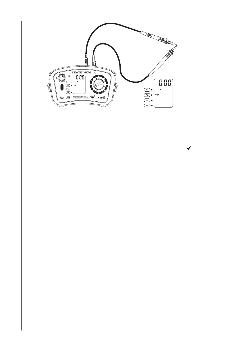
13 Volts
1. Press the Power button and turn on the instrument. Turn the rotary switch
and select the VOLTS function.
2. Insert the Test Leads into the instrument. (Fig.50)
Fig. 50
3. Voltage value and frequency will be displayed on the LCD when applying AC
voltage.
Note : A message DC V may be displayed when measuring AC voltages with
frequencies out of the range 45Hz - 65Hz.
14 Touch
Pad
15 Back
Light
1. The touch pad measures the potent
testers PE terminal. A message PE HiV is displayed on the LCD with the
audible buzzer if a potential difference of 100V or more is present between
the operator and the PE terminal at touching the Touch pad.
2. Touch Pad function can be enabled and disabled (ON / OFF); refer to 6.
Configuration in this manual and select ON or OFF. In case that OFF is
a w
selected,
sound.
* Initial value: ON
Note : A message PE HI V may be displayed when testing inverters or
measuring voltages containing high frequencies even if a user isn't
touching with the Touch Pad.
Pressing the Back Light Button selects Backlight ON / OFF. Backlight
automatically turns off in 60 sec after it turns on. Backlight at powering o
t
he instrument can be set either ON or OFF. Refer to 6. Configuration in this
manual how to select ON / OFF.
arning for PE HiV does not appear and the buzzer does not
ial between the operator and the
n

48
Measured result at each function can be saved in the memory of the
250V
MΩ
18.52
ALL DELETE
MEMORY MODE
ESC:MEM BUTTON
DELETE
RECALL
PAT OFF
SAVE
instrument. (MAX : 1000)
16.1 How to save the data
Save the result according to following sequence.
(1) Measured result.
Fig. 51-1
16 Memory
Function
(2) Press
to enter into SAVE MODE.
Fig. 51-2
(3) Press
▲ In case of PAT mode
(Insulation or Continuity function)
1.ID No
2.SITE No
3.DATA No
to enter into SAVE MODE.
▲ Other
1. TYPE (Selection items are shown
in the table below)
2. CIRCUIT No
3. BOARD No
4. SITE No
5. DATA No
Press the SELECT Button to choose the parameter to change.
▲In case of PAT mode : ID No → SITE No →MENU→DATA No
When saving an insulation test the ID No, automatically advances by 1.
▲Other : TYPE → CIRCUIT No → BOARD No → SITE No →MENU→ DATA No
If you select MENU and press F4(OK) switch, Recall / delete screen will
be displayed.(Fig 52-2). You can recall or delete the saved d
delete screen. Use the UP or DOWN Button and change settings.
TYPE Selection
Continuity
Insulation L/L, L/N, L/E,N/E
Loop(L-PE) Zs, Z
RCD
r1, r2, rn, R1+R2, R2
1st RCCB, 2nd RCCB,
3rd RCCB, RCBO
E
Ke ep th e UP / DO W N Ke y
presse d do wn to alter the
number quickly.
ata at Recall /

49
Normal mode
Saving
250V
PAT OFF
MΩ
18.52
SAVE
INSULATION
18.52M
Ω
250V
SITE : 01
BOARD : 01
CIRCUIT : 01
TYPE : L/L
SAVE MODE
DATA No.001
BACK
Memory
Function
(4) Press OK ( ). (Confirmed)
(5) SAVING is displayed for about 2
sec on the LCD, and then returns to
the start screen. Saving completes.
Returns to Normal mode once data
save comple t e s . (Measu re m e n t
mode)
Fig. 51-3
Fig. 51-4

50
16.2 Recall the saved data
ALL DELETE
MEMORY MODE
ESC:MEM BUTTON
DELETE
RECALL
SAVE
DOWN
UP
TYPE : L/L
BACK
INSULATION
18.52M
Ω
250V
SITE : 01
BOARD : 01
CIRCUIT : 01
RECALL MODE
DATA No.
000
250V
PAT OFF
MΩ
Save data can be displayed on LCD according to following sequence.
(1) Press to enter into Recall/
delete screen.
Memory
Function
Fig. 52-1
(2) Press
MODE.
(3) Press Up (
to enter into RECALL
) or DOWN ( )
and select Data No.
Keep the UP/DOWN Key
pressed down until a buzzer
sounds to skip the number
co n ta ini n g no da ta an d
display the next data.
Fig. 52-2
Fig. 52-3

51
DELETE ALL
DELETE
ALL DELETE
MEMORY MODE
ESC:MEM BUTTON
DELETE
RECALL
SAVE
ALL DELETE
Delete All?
ESC:MEM BUTTON
BACK
DELETE
DELETE MODE
DOWN
UP
DATA No.
000
INSULATION
18.52M
Ω
250V
BACK
TYPE : L/L
SITE : 01
BOARD : 01
CIRCUIT : 01
250V
PAT OFF
MΩ
Memory
Function
16.3 Delete the saved data
Save data can be deleted according to following sequence.
Fig. 53-1
(1) Press to enter
into Recall / d e let e
screen.
(2) Press
enter into
DELETE MODE
to
(3) Press Up
(
) or
DOWN (
and select Data
No.
)
Fig. 53-2
(2) Press to
enter into ALL
DELETE MODE
(4) Press
DELETE (
(Confirmed)
Fig. 53-3 Fig. 53-4
).
(3) Press ALL
DELETE
(
).
(Confirmed)

52
ALL DELETEDELETE
Deleting
All Deleting
DELETE
DELETE MODE
DATA No.001?
INSULATION
18.52M
Ω
250V
BACK
TYPE : L/L
SITE : 01
BOARD : 01
CIRCUIT : 01
250V
PAT OFF
MΩ
250V
PAT OFF
MΩ
Memory
Function
Fig. 53-5
(5) Press
DELETE
).
(
(Confirmed)
Fig. 53-7
(6) Returns to Normal mode when
selected data deleted.
(Measurement mode)
Fig. 53-9
Fig. 53-6
Fig. 53-8
(4) Returns to Normal mode when
selected data is deleted.
(Measurement mode)

53
Memory
Function
16.4 Transfer the stored data to PC
The stored data can be transferred to PC via Optical Adapter Model8212USB
(Optional Accessory).
Fig. 54
●How to transfer the data:
(1) C o n n ec t Mo de l8 2 1 2 U S B to t h e
USB Port of a PC.(Special driver for
Model8212USB should be i nstalled.
S e e t h e i n st ru ct io n ma nu a l f o r
Model8212USB for further details.)
(2) Insert Model8212USB into the KT65DL
as shown in Fig 55.
hould be removed from the
Test Leads
KT65DL at this time.
(3) Power on the KT65DL . (Any function is OK.)
(4) Start special software "KEW Report" on your PC and set the communication
port.
Then click "Down load" command, and the data in the KT65DL will be
transferred to your PC.
Please refer to the instruction manual of Model 8212USB and HELP of
KEW Report for further details.
s
Fig. 55
Note: Use "KEW Report
" with version 2.20 or more
.

54
17.1 If the symbol ( )appears, this means that the test resistor is too hot
and the automatic cut out circuits have operated. Allow the instrument
to cool down before proceeding. The overheat circuits protect the test
resistor against heat damage.
17.2 The test button may be turned clockwise to lock it down. In this auto
mode, when using distribution board lead ACC065, tests are conducted
by simply disconnecting and r
ACC065 avoiding the need to physically press the test button i.e. 'hands
free'.
econnecting the red phase prod of the
17 General
17.3 When the display shows the low battery indication, (
the test leads from the instrument. Remove the battery cover and the
batteries.
17.4 If at any time during testing there is a momentary degradation of
reading, this may be due to excessive transients or discharges on
the system or local area. Should this be observed, the test should
be repeated to obtain a correct reading. If in doubt, always contact
Kewtech.
), disconnect

55
Screw
Spare Fuse
Fuse
-
+
+
-
-
+
+
-
18 Battery
replacement
When the display shows the low battery indication, , disconnect the test
leads from the instrument. Remove the battery cover and the batteries.
Replace with eight (8) new 1.5V AA batteries, taking care to observe correct
polarity. Replace the battery cover.
19 Fuse
replacement
The continuity test circuit is protected by a 600V 0.5A HRC ceramic type fuse
situated in the battery compartment, together with a spare. If the instrument
fails to operate in the continuity tes
from the instrument. Next remove the battery cover, take out the fuse and
test its continuity with another continuity tester. If it has failed, replace it with
a spare, before refitting the battery cover. Do not forget to obtain a new fuse
and place it in the spare position. If the instrument will not operate in the loop
impedance, PSC/PFC and RCD modes, it m
fitted on the printed circuit board have blown. If you suspect that the fuses
have failed, return the instrument to Kewtech for service - do not attempt to
replace the fuses yourself.
t mode, first disconnect the test leads
ay be that the protective fuses
Fig. 56

56
If this tester should fail to operate correctly, return it to Kewtech marked for
the attention of the Service Department, stating the exact nature of the fault.
Make sure that:
a. operating instructions have been followed
b. leads have been inspected
c. the unit is returned with all accessories
Regular re-calibration is recommended for this instrument. We recommend
that with normal use, the instrument
month interval. When this is due for re-calibration return it to Kewtech marked
for the attention of the Calibration Department and be sure to include all
accessory leads, as they are part of the calibration procedure. The mains
lead supplied with this instrument (KAMP12) for testing at sockets is part
of the instrument. It directly affects the accuracy of
readings. As such always keep it with the instrument and remember to return
it with the instrument when servicing and calibration is required. If other leads
are used then readings may not be correct unless they are calibrated with the
instrument. If this product needs cleaning use a lightly damp cloth to wipe its
surfaces.
DO NOT use strong cleaning agents as these may damage
surfaces. Kewtech reserve the right to change specifications and design
without notice and without obligation.
is calibrated at least once in every 12
the loop and PSC/PFC
the plastic
20 Servicing
and Calibration

57
21
Pat test with
the Pat adapter 1
Using the Kewtech Pat adapter with the KT65DL to undertake portable
appliance testing
Before each use the adapter should be inspected to ensure that it is not
damaged in any way. If any damage is noticed the adapter should be
withdrawn from service and replaced.
1. Earth Bond.
a. This is a continuity test. Connect the test leads to the instrument as shown
b. Connect one test
c. Plug the appliance to be tested into the three pin socket on the front of the
d. Connect the other test lead from KT65DL to the earthed position on your
e. Conduct a test.
Note: The test lead resistance can be auto-nulled from the test result, see
section 7.1 for guidance
2. I
a. Connect the test leads to the instrument as shown in figure 20 on page 23
b. Connect one test probe from the KT65DL to the terminal marked
c. Plug the appliance to be tested into the three pin socket on the front of the
d. Conduct a test.
3. Insulation Class I
a
b. Connect one test probe from the KT65DL to the terminal marked
c. Plug the appliance to be tested into the three
pin socket on the front of the Pat Adapter
d. Connect the other lead from the KT65DL to
the parts of your appliance to be tested.
e. Conduct a test
In Pat CL I
1000V range is disabled. Use 250V for:
1) Appliances and extension leads which
include surge protection.
2) Where sensitive electronic equipment
could be damaged.
in figure 12 on page 17
lead from the KT65DL into the Pat Adapter 1 at the
terminal marked E (Earth Testing)
Pat Adapter
appliance to be tested.
nsulation Class I
L-
(Insulation Testing) on the Pat Adapter 1 and the other test lead to the
N
terminal marked E (Earth Testing)
Pat Adapter
I
. Connect the test leads to the instrument as shown in figure 20 on page 23
L-N
(Insulation Testing) on the Pat Adapter 1
or Pat CL II mode the insulation
Fig. 57

58
22.1 Maximum earth fault loop impedance (Zs) for fuses with Uo of 230V
All tables have had the Cmin factor applied according to the BS7671:2008
Ammendment 3 (2015)
Protection
type
Rating
0.4s 5s
(A)
Zs (Ω) Zs (Ω) Zs (Ω) Zs (Ω) Zs (Ω) Zs (Ω) Zs (Ω) Zs (Ω)
5
-- - - - - - -
6 7.80 12.00 6.24 9.60
10 4.65 6.80 3.72 5.44
16 2.43 4.00 1.95 3.20 2.30 3.90 1.84 3.12
20 1.68 2.80 1.35 2.24 1.93 3.20 1.54 2.56
25 1.29 2.20 1.03 1.76
32 0.99 1.70 0.79 1.36 0.91 1.60 0.73 1.28
40
-45 1.00 0.80
50
-60
63
-80
--
100
--
BS88-2 Fuse
ref BS7671:2008 (2015)
0.4s@80%Z
1.30
--
0.99
--
0.78
--
0.55
--
0.42
--
BS88-3 Fuse
ref BS7671:2008 (2015)
5s@80%Z
0.4s 5s
9.93 14.60 7.94 11.68
- -
- -
- -
1.04
0.79
0.62 0.68 0.55
0.44 0.51 0.41
0.34 0.38 0.30
-
-
0.4s@80%Z
5s@80%Z
22 Zs tables
Protection
type
Rating
(A)
0.4s 5s
Zs (Ω) Zs (Ω) Zs (Ω) Zs (Ω) Zs (Ω) Zs (Ω) Zs (Ω) Zs (Ω)
BS3036
ref BS7671:2008 (2015)
0.4s@80%Z
5s@80%Z
BS1362
ref BS7671:2008 (2015)
0.4s 5s
0.4s@80%Z
3 15.60 22.00 12.48 17.60
5 9.10 16.80 7.28 13.44
13 2.30 3.64 1.84 2.91
15 2.43 5.08 1.94 4.07
20 1.68 3.64 1.35 2.91
30 1.04 2.51 0.83 2.01
45 1.51 1.21
60 1.07 0.86
100 0.51 0.41
Protection
type
Rating (A)
0.4s 5 s
Zs (Ω) Zs (Ω) Zs (Ω) Zs (Ω)
BS1361
ref 7671:2001
0.4s@80%Z
5s@80%Z
5 10.36 16.25 8.28 13.00
15 3.26 4.96 2.61 3.97
20 1.69 2.78 1.35 2.23
30 1.14 1.82 0.91 1.46
45 0.57 0.95 0.46 0.76
60 0.69 0.55
80 0.49 0.40
100 0.36 0.29
5s@80%Z

59
22.2 Maximum earth fault loop impedance (Zs) for RCBOs and MCBs
with Uo of 230V
Zs BSEN 60898 MCB & BSEN61009-1 RCBO Table
MCB (Disconn. time
0.4 and 5s)
B C D D B C D D
Current
rating
Current
rating
Zs (Ω) Zs (Ω) Zs (Ω) Zs (Ω) Zs (Ω) Zs (Ω) Zs (Ω) Zs (Ω)
6 7.28 3.64 1.82 3.64 5.82 2.91 1.46 2.91
10 4.37 2.19 1.09 2.19 3.50 1.75 0.87 1.75
16 2.73 1.37 0.68 1.37 2.18 1.09 0.55 1.10
20 2.19 1.09 0.55 1.09 1.75 0.87 0.44 0.87
25 1.75 0.87 0.44 0.8
32 1.37 0.68 0.34 0.68 1.09 0.55 0.27 0.54
40 1.09 0.55 0.27 0.55 0.87 0.44 0.22 0.44
50 0.87 0.44 0.22 0.44 0.70 0.35 0.17 0.35
63 0.69 0.35 0.17 0.35 0.55 0.28 0.14 0.28
MCB (Disconn. time 0.4 and 5s)
1 2 3 4 1 2 3 4
Zs (Ω) Zs (Ω) Zs (Ω) Zs (Ω) Zs (Ω) Zs (Ω) Zs (Ω) Zs (Ω)
5 10.93 6.41 4.37 0.87 8.74 5.13 3.50 0.70
6 9.10 5.21 3.64 0.73 7.28 4.16 2.91 0.59
10 5.46 3.10 2.19 0.44 4.37 2.48 1.75 0.35
15 3.64 2.08 1.45 0.29 2.91 1.66 1.16 0.24
16 3.41 1.95 1.37 0.28 2.73 1.56 1.09 0.22
20 2.73 1.56 1.09 0.22 2.18 1.25 0.87 0.17
25 2.19 1.24 0.87 0.17 1.75 1.00 0.70 0.14
30 1.82 1.
32 1.71 0.98 0.68 1.37 0.78 0.55
40 1.36 0.78 0.55 1.09 0.62 0.44
50 1.09 0.63 0.44 0.87 0.50 0.35
63 0.86 0.49 0.35 0.69 0.40 0.28
MCB (Disc
0.4s)
05 0
MCB (Disc
Zs BS3871 MCB table
.73 1.46 0.84 0.59
MCB (Disconn. time
5s)
0.4 and 5s) @0.8 Z
.40 0.70 0.35 0.70
7 1
MCB (Disconn. time 0.4 and 5s)@0.8 Z
MCB (Disc
0.4s)
@80%
MCB (Disc
5s)
@80%

60
Correct assembly is shown in Fig 58, 59 and 60. By hanging the instrument
round the neck, both hands will be left free for testing.
1. Attach the Buckle to the KT65DL as shown in Fig.58.
Match the hole of the Buckle and
the protrusion at the side face of
KT65, and slide it upwards.
Fig. 58
2. How to install the Strap belt
Pass the strap belt down through
the buckle from the top, and up
through the slots of the probe case
from the bottom.
23 Case and
strap
assembly
Fig. 59
3. How to fasten the Strap belt
Fig. 60
Pass the strap through the buckle,
ad just the strap for length and
secure.

Kewtech Corporation Ltd.
Midas House, Unit 2b
Stones Courtyard
High Street, Chesham
Buckinghamshire HP5 1DE
www.kewtechcorp.com
61
 Loading...