

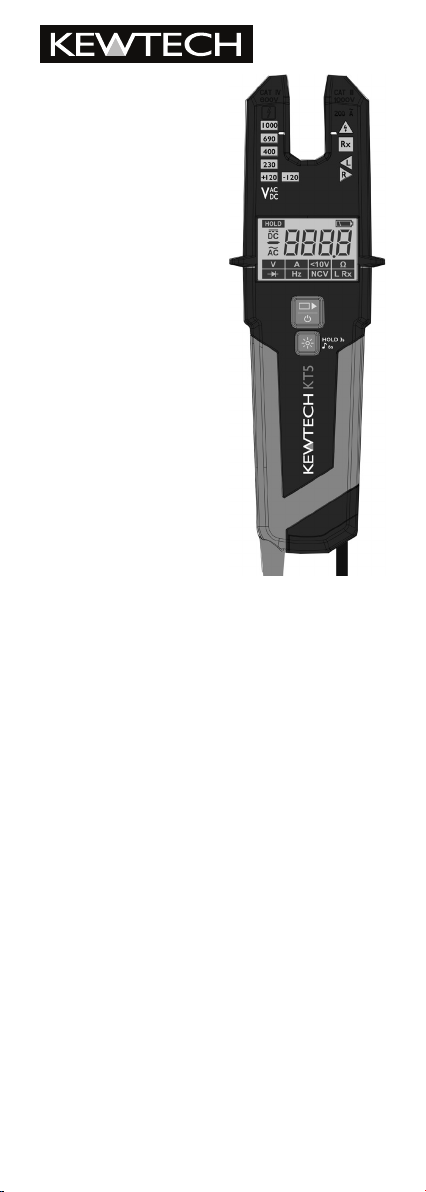
KT5
Current Voltage
Tester
Content
1.0 Introduction / Product Package
2.0 Safety Measures
3.0 Danger of electric shock and other dangers
4.0 Intended Use
5.0 Testers Information
6.0 Preparation for tests
6.1 Auto-power on/ switching on
6.2 Auto-power off
7.0 Conducting Tests
7.1 Voltage test
7.1.1 Low Voltage mode
7.2 Current Test
7.3 Single-pole phase test
7.4 Phase rotation test
7.5 Continuity test
7.6 Diode test
7.7 Resistance test
7.8 Frequency test
7.9 NCV Test
7.10 Torch light
7.11 Self test
7.12 HOLD Function
7.13 Backlight
8.0 Battery Replacement
9.0 Technical Data
10.0 Cleaning and storage
Warranty
References marked on instrument or in instruction
manual:
Warning of a potential danger, follow with instruction
manual.
Reference! Please use utmost attention.
Caution! Dangerous voltage. Danger of electrical
shock.
Continuous double or reinforced insulation category II
IEC 536 / DIN EN 61140.
Equipment for working under live voltage.
Conformity symbol, the instrument complies with the
valid directives. It complies with the EMV Directive
(2014/30/EU), Standard EN 61326-1 are fullled. It also
complies with the Low Voltage Directive (2014/35/EU),
Standard EN61243-3:2014 is fullled.
UK Conformity compliance mark
Tester complies with the standard
(2012/19/EU) WEEE.
The instruction manual contains information
and references, necessary for safe operation and
maintenance of the tester.
Prior to using the tester (commissioning/ assembly)
the user is kindly requested to thoroughly read the
instruction manual and comply with it in all sections.
Failure to read the tester manual or to comply with
the warnings and references contained herein can
result in serious bodily injury or tester damage.
The respective accident prevention regulations
established by the professional associations are to be
strictly enforced at all times.
Voltage tester is not a measurement device, it is only
allowed to use for testing purposes.
1.0 INTRODUCTION / PRODUCT PACKAGE
The KT5 is a universal tester for voltage, current, continuity
and rotary eld testing with various secondary features.
It complies with the standard for two pole voltage testers
EN61243-3:2014.
The KT5 is characterized by the following features:
• Designed to meet international safety standards
EN61243-3:2014
• Measurement Category CAT IV / 600 V Measurement
Category CAT III / 1000 V
• AC and DC voltage test up to 1000 V with LEDs
• Current test up to 200 AC
• AC voltage test up to 1000 V and DC voltage test up to
1500 V with LCD
• Cable break tests by Non Contact Voltage detection
• Polarity indication
• Single-pole phase test
• Phase rotation test and Continuity test
• Resistance measurement
• Frequency measurement
• Vibration motor
• Auto-power ON / OFF
• Torch light and IP64 protection
After unpacking, check that the instrument is
undamaged.
The product package comprises:
1 pc Tester KT5
2 pcs batteries 1.5V, IEC, LR03 (AAA)
1 pc operating instructions
2.0 SAFETY MEASURES
The testers have been constructed and tested in
accordance with the safety regulations for voltage
testers and have left the factory in a safe and perfect
condition.
The operating instructions contain information and
references required for safe operation and use of
the tester. Before using the tester, read the operating
instructions carefully and follow them in all respects.
Depending on the internal impedance of the voltage
tester there will be a different capability of indicating
the presence or absence of operating voltage in case
of the presence of interference voltage.
A voltage tester of relatively low internal impedance,
compared to the reference value of 100 k�, will not
indicate all interference voltages having an original
voltage value above the ELV level. When in contact
with the parts to be tested, the voltage tester may
discharge temporarily the interference voltage to a
level below the ELV, but it will be back to the original
value when the voltage tester is removed.
When the indication “voltage present” does not
appear, it is highly recommended installing earthing
equipment before work.
A voltage tester of relatively high internal impedance,
compared to the reference value of 100 k�, may not
permit to clearly indicate the absence of operating
voltage in case of presence of interference voltage.
When the indication “voltage present” appears on
a part that is expected to be disconnected of the
installation, it is highly recommended conrming by
another means (e.g. use of an adequate voltage tester,
visual check of the disconnecting point of the electric
circuit, etc.) that there is no operating voltage on the
part to be tested and to conclude that the voltage
indicated by the voltage detector is an interference
voltage.
A voltage tester declaring two values of internal
impedance has passed a performance test of
managing interference voltages and is (within
technical limits) able to distinguish operating voltage
from interference voltage and has a means to directly
or indirectly indicate which type of voltage is present.

3.0 DANGER OF ELECTRIC SHOCK AND OTHER
HOLD 3s
♪
6s
1000
690
400
230
120
120+
R
L
Rx
V
AC
DC
DANGERS
To avoid an electric shock, observe the precautions when
working with voltages exceeding 120 V (60 V) DC or
50 V (25 V) eff AC. In accordance with DIN VDE these
values represent the threshold contact voltages (values in
brackets refer to limited ranges, e.g. in agricultural areas).
The tester must not be used with the battery
compartment open
Before using the tester, ensure that the test lead and
device are in perfect working order. Look out e.g. for
broken cables or leaking batteries.
Hold the tester and accessories by the designated grip
areas only, the display elements must not be covered.
Never touch the test probes.
The tester may be used only within the specied
measurement ranges and in low-voltage installations up
to 1000VAC and 1500VDC.
The tester may be used only in the measuring circuit
category it has been designed for.
Before and after use, always check that the tester is in
perfect working order (e.g. on a known voltage source
such as the KEWPROVE3 opening unit).
Make sure that the cables tested for current are double
insulated.
The tester must no longer be used if one or more
functions fail or if no functionality is indicated.
It is not permitted to use the tester during rain or
precipitation.
An accurate display is guaranteed only within a
temperature range of -15°C to +55°C at relative air
humidity less than 85%.
If the safety of the user cannot be guaranteed, the tester
must be switched off and secured against unintentional
use.
Safety is no longer guaranteed e.g. in the following cases:
− obvious damage
− broken housing, cracks in housing
− if the tester can no longer perform the required
measurements/ tests
− stored for too long in unfavorable conditions
− damaged during transport
− leaking batteries
The tester complies with all EMC regulations.
Nevertheless it can happen in rare cases that electric
devices are disturbed by the electrical eld of the tester
or the tester is disturbed by electrical devices.
Never use the tester in explosive environment
Tester must be operated by trained users only
Operational safety is no longer guaranteed if the tester
is modied or altered.
The tester may be opened by an authorized service
technician only.
The current test may only be performed on double
insulated cables.
4.0 INTENDED USE
The tester may be used only under the conditions and for
the purposes for which it was designed. Therefore, observe
in particular the safety instructions, the technical data
including environmental conditions.
5.0 TESTERS INFORMATION
1. Opening for current measurement
2. Test leads (on back side)
3. LED display
4. LCD display
5. On/Off and function button
6. Torchlight and hold button
7. Battery compartment
8. Sensor for cable break detection, NCV
1
8
2
3
4
5
6
7
LED Display information
1. Voltage indication
2. Polarity indication (120V LEDs)
3. ELV / Single pole indication /
Live circuit LED
4. Continuity indication
5. Rotary eld indication
1000
1
690
400
230
120+
120
2
AC
V
DC
Rx
L
R
3
4
5

LCD Display information
1. HOLD symbols
2. AC/ DC and polarity symbols
3. Function symbols (from left to right, upper row: voltage
test, current test, low voltage test, resistance test; lower
row: diode test, frequency test, cable break detected by
NCV, continuity test).
4. Low battery indication
5. 4 digit 7 segment display
1
2
4
5
3
6.0 PREPARATION FOR TESTS
6.1 Auto-power-on/ switching on
• The tester switches on when it detects shorten tips, or
an AC or DC voltage above approx. 6 V or a live phase
on L2+ (single pole test).
• It can be switched on with a button.
6.2. Auto-power off
• Tester is automatically powered off after approx.
10 sec when there is no signal contacted to the probes.
• The torch light automatically switches off after approx.
30 sec.
7.0 CONDUCTING TESTS
7.1 Voltage test
• Connect both probes to the object under test.
• The voltage is indicated by LEDs if >120 V.
• The buzzer and vibration function turn on if the voltage
is higher than 50 V AC or 120 V DC.
• Voltage polarity is indicated in following manner on the
LCD.
AC: AC symbol is on
+DC: DC symbol is on
-DC: - symbol and DC symbol is on
• Above 120 V, the polarity is shown on the LED display
as well.
AC: both 120 V LEDs are on
+DC: left 120 V LED is on
-DC: right 120 V LED is on
• Once the tester is powered on, it will automatically
measure voltage in range 6V-1000VAC/1500VDC.
When the L2 probe + is the positive (negative)
potential, the Polarity indication LED indicates
“+DC” (“-DC”).
During voltage test, L or R LED/Symbol may light up.
In case of empty batteries, only the ELV LED lights up
>50 V.
7.1.1 Low Voltage mode – 1V-1000VAC/1500VDC
• Press On/Off/Function button repeatedly until the
LCD shows <10V symbol.
• In Low Voltage mode it is possible to measure AC and
DC voltage from 1V.
• Connect both probes to the object under test.
• Voltage display is as in 7.1 described.
Continuity mode is disabled in Low Voltage Mode.
7.2 CURRENT TEST
• Press On/off/ Function button repeated until LCD
shows A symbol.
• In current test mode, currents between 0.1 A and
200 A can be tested.
• The cable under test needs to be positioned in the
centre of the opening and adjacent to the two markings
on either side of the the moulding.
• Make sure that only double insulated cables are
measured.
• Store test probes safely to avoid any unintended
connection.
• The tester will automatically switch to voltage
measurement if a voltage is detected >6 V.
7.3 SINGLE-POLE PHASE TEST
Function of this test may not be fully achieved if
the insulation condition / grounding conditions of
user or of the equipment under test are not good
enough. Verication of live-circuit should not be
dependent on this Single-pole phase test only, but
on the voltage test (as in 7.1).
• Hold the tester rmly in your hand. Connect the “L2
+” probe to the object under test. Live circuit LED
lights up and the buzzer sounds when a voltage of
approx. 100 V AC or more exists in the object under
test. (Pol≥100 V AC).
• Indication of Single Pole phase test is via LED.
7.4 PHASE ROTATION TEST
• L LED (symbol) and R LED (symbol) for Phase rotation
test may operate on various wiring systems, but
effective testing result can be obtained only on a threephase 4-wire system.
• Hold the tester rmly in your hand and connect both
probes to the object under test.
• Phase-to-phase voltage is indicated by Voltage LEDs
and LCD.
• R LED lights up for Right rotary eld.
• L LED lights up for Left rotary eld.
• Measurement principle: The instrument detects the
phase rising order regarding the user as earth.
Function of this test may not be fully achieved if the
insulation condition/ grounding conditions of the
user or of the equipment under test is not good
enough.

7.5 CONTINUITY TEST L RX
Make sure the object under test is not live.
• Connect both test probes to the object under test.
• Continuity is shown by the lighting up of the continuity
LED and a sound if resistance is below 500 kOhm.
• If a lower threshold for continuity is preferred, low
continuity mode can be selected.
· Press Torchlight-function button repeatedly until
the LRx symbol is shown on the LCD.
· Continuity is shown by the lighting up of the LED
and sound if resistance is below 20 Ohm.
The continuity test is performed automatically in
all modes except in Low Voltage and Resistance
mode.
The tester automatically switches to voltage
measurement if a voltage is detected >6 V - during
continuity testing.
7.6 DIODE TEST
Make sure the object under test is not live.
• Switch into diode testing mode by pressing On/Offfunction button repeatedly until symbol is shown
on the LCD. Connect both test probes to the diode
under test.
The continuity LED lights and the buzzer sounds
when L1 is connected to the anode and L2 is
connected to the cathode.
Continuity indication will be off if L1 tip is
connected on Cathode of diode and L2 tip on
Anode.
Tester automatically switches to voltage
measurement if voltage >6 V or Single pole is
detected during diode testing.
7.7 RESISTANCE TEST
Make sure the object under test is not live.
• Switch into resistance measurement by pressing On/
Off-function button repeatedly until the k� symbol is
shown on LCD. Connect both test probes to the object
under test. Resistance up to 100 k� can be shown on
LCD. For resistance less than ~20� buzzer sounds
continuously to indicate low continuity.
Tester automatically switches to voltage measurement if
voltage >15 V or Single Pole is detected.
7.8 FREQUENCY TEST
• Switch into frequency measurement by pressing the On/
Off-function button repeated until Hz symbol is shown
on the LCD. Connect both test probes to the AC
voltage under test. Frequency from 1 Hz to 800 Hz can
be shown on LCD.
Frequency measurement is possible for voltages >10V AC.
The level of voltage will be shown only on bar graph
for voltages >120 V. ELV diode will indicate voltages
>50 V AC and >120 V DC.
7.9 CABLE BREAK DETECTION BY NCV
• Switch into NCV detection by pressing On/offfunction button repeatedly. LCD will show the NCV
symbol.
• The NCV function is used to nd where the cable
breaks.
• Hold the voltage tester with the sensor against
the wire or cable. The voltage tester indicates the
strength of the signal digitally on the LCD screen.
• Store test probes safely to avoid any unintended
connection.
• Tester automatically switches to voltage measurement
if voltage >6 V or single pole is detected between
probes.
7.10 Torch light
• Press the “torchlight” button to turn on the light and
after approx. 30 s it will turn itself off.
7.11 Self test
• LEDs and all LCD segments and vibration motor,
torch light, ELV indication and buzzer are turned on
for a second after battery replacement.
Self test can be activated:
Shorting L1(-) and L2(+) probe tips while
device is turned OFF – leave device OFF for 30
seconds before shorting tips.
7.12 HOLD Function
• A long press (2 seconds) of the “torchlight/function”
button activates HOLD function and freezes display
value. With another quick press of the on “torchlight/
function” button freezing of display is released. When
the HOLD function is active symbol will be
shown on LCD.
7.13 Backlight
• White Backlight is turned on when torch light is
turned on.
8.0 BATTERY REPLACEMENT
Remove the probes from any testing point, when
opening the battery case. Batteries are dead
when the continuity test with both test probes
connected cannot be done anymore and the low
battery symbol is shown in the LCD.
Follow the procedure below and replace batteries
with new ones (type IEC LR03 1.5 V).
• Unscrew the battery door
• Pull out the battery door and replace the batteries.
Insert new batteries according to the engraving on
the battery door.
• Re-assemble battery door.
Conrm that the battery door case is properly
locked prior to measurements.

9.0 TECHNICAL DATA
Voltage Range
LED nominal Voltage
LED tolerances
ELV indication LED
Response time
LCD Range
LCD Resolution
LCD Accuracy
LCD Overrange
indication
Current Test
Safety current
Measurement Duty
Internal battery
consumption
Single-pole phase
test voltage range
Phase rotation test
Continuity test
Resistance
measurement
Frequency
measurement
NCV Test
Battery
Temperature
Humidity
Altitude
Overvoltage
Standard
Protection
1…1000 V AC (15…800 Hz),
1…1500 V DC(±)
120 / 230 / 400 / 690 / 1000 V
EN 61243-3
>50 V AC, >120 V DC
<1s at 100% of each nominal
1…1000 V, AC (15…800 Hz),
1…1500 V DC(±)
0.1 V (1…29.9 V), 1 V
±3% ±1.5 V (1…29.9 V)
±3% ±3dgt (30…1500 V)
“OL”
0.1…200 A AC(+/-3%+5Dgt)
Resolution 0.1 A
Frequency range 45…65 Hz
Is<3.5 mA (at 1000 V AC),
<6 mA at 1500 V DC
30 s ON, 240 s OFF
approx. 120 mA
100…1000 V AC (50/60 Hz )
170…1000 V phase-to-phase,
AC (40...70 Hz)
0…500 k� + 50%
0…100 k�; accuracy:
±5%±10dgt@25°C;
resolution: 1 � (1-2000 �)
1 k� (2-100 k�)
1…800 Hz ±5%±5dgt;
resolution: 1 Hz
100...1000 V AC (50/60 Hz)
3 V (IEC LR03 1.5 V x 2)
-15…55°C operation;
-20…70°C storage;
No condensation
max. 85% RH
up to 2000 m
CAT IV / 600 V, C AT III / 1000 V
EN/IEC 61243-3:2014
IP64
10.0 CLEANING AND STORAGE
Tester does not need any special maintenance if
used according to user manual.
Remove tester from all test points before cleaning.
Use a lightly damp cloth with neutral detergent
for cleaning the instrument. Do not use abrasives
or solvents.
Do not expose the instrument to direct sun light,
high temperature and humidity or dewfall.
Remove batteries when the instrument will not be
in use for a long period.
WARRANTY
Our instruments are subject to strict quality control.
However, should the instrument function improperly
during normal use, you are protected by our 2 year
warranty (valid with invoice or receipt).
Within the warranty period we will decide whether
to exchange or repair the defective instrument. We
will repair free of charge any defects in workmanship
or materials, provided the instrument is returned
unopened and untampered with.
Damage due to dropping or incorrect handling are
not covered by the warranty. If the instrument shows
failure following expiry of warranty our service
department can offer you a quick and economical
repair.
Subject to changes without notice.

Certicate of Conformity
and Warranty
Product:
KT5 Current Voltage Detector
This instrument has been calibrated
using equipment which has itself been
calibrated to standards traceable to
International Standards monitored by
BIPM (International Bureau of Weights
and Measures).
This certicate guarantees that the
product has been fully inspected and
conforms to all the relevant published
specications.
FREE TWO YEAR GUARANTEE
Kewtech’s Two Year Warranty enhances
customers’ legal rights. It covers all
manufacturing defects for a two year
period but Kewtech reserves the right to
exclude abuse or accidental damage.
RE-CALIBRATION SERVICE
Regular re-calibration is recommended
for this instrument. Kewtech recommends
that with normal use the instrument be
calibrated at least once in every 12 month
period. When the instrument is due for
re-calibration return it to the address
below marked for the attention of the
Calibration Department.
Simply go to kewtechcorp.com to register your
Unit 2, Shaw Wood Business Park, Shaw Wood Way,
Doncaster DN2 5TB T: 01494 792 212
instrument
Kewtech Corporation Limited
kewtechcorp.com
 Loading...