


KT400
Loop Impedance & PSC / PFC Tester
Operating Instructions
1
kewtechcorp.com

1. SAFETY
1.1 Equipment Markings
>
550V
2
CAT
IV
300V
CAT
III
500V
Caution - refer to the instruction manual.
Construction is double insulated.
Product should be recycled as electronic waste.
Conforms to EU standards.
Prohibited to use on Electrical Systems which use voltages
above 550V.
Measurement Category IV is applicable to testing and
measuring circuits at the origin of the installations supply.
They are utility level CAT checks. This part of the installation
is expected to have a minimum of one level of over-current
protective device between the transformer and connecting
points of the measuring circuit.
This tester’s voltage rating for CAT IV locations is 300V,
where the voltage is Phase (line) to Earth.
Measurement Category III is applicable to testing and
measuring circuits connected after the source of the
building’s low-voltage MAINS installation. This part of the
installation is expected to have a minimum of two levels of
over-current protective devices between the transformer and
connecting points of the measuring circuit.
Examples of CAT III are measurements on devices installed
after the main fuse or circuit breaker xed within the building
installation. Such as distribution boards, switches and
socket outlets.
This tester’s voltage rating for CAT III location is 500V where
the voltage is Phase (line) to Earth.
1.2 Operational Safety
The KT400 is designed to be used by skilled persons in accordance
with safe methods of work. If the KT400 is used in a manner not
specied by Kewtech, the protection provided by it may be impaired.
Inspect the product before using. If any damage is visible; such as
cracks in the casing, damage to any accessories, leads or probes,
the unit should not be used.
Do not operate the KT400 with the battery cover off as this will
compromise the insulated safety barrier.
To maintain safety, ensure serviceability and to monitor accuracy of
the KT400, the tester should be checked on a checkbox such as the
Kewtech FC2000 checkbox at regular intervals.
Although fully protected against over voltage up to 440V, the tester
should only be used on 230V systems.
Contents
KT400 Loop Impedance and PSC/PSF Tester
KAMP 12 Mains lead
Batteries
Carry Case
Manual
Optional
ACC063 distribution board lead set
Kewcheck R2 - socket test lead adapter
Lightmates – test lead adapters for lighting points
3
kewtechcorp.comkewtechcorp.com

2. DESCRIPTION
The KT400 is a no trip and high current, high resolution digital earth
loop impedance tester.
2.1 Features
• No Trip LOOP L-E test
• High current L-E loop test
• High current, High resolution L-E loop test
• High current, High resolution L-N loop test
• AC Voltage VLN - VLE - VNE
• Distribution network operator polarity test pad
• PFC / PSC measurements
• Hands free function
• Polarity, voltage present LED
4
• Auto switch off function for battery preservation.
2.2 Indication
The white display backlight will illuminate on switching on and during
testing. To preserve battery life the backlight will switch off after
approximately 4 seconds of inactivity. The unit will automatically
power off after approximately 3 minutes of inactivity. To switch the
tester back on after auto power off, press any button.
Battery status
3. USAGE
Volts Present /
Polarity LED
Voltage LN/LE/
NE toggle button
Hands Free
selection button
PFC - PSC /
Voltage
toggle button
5
Rotary
selection dial
Polarity
touch pad
Mains
Mains voltage
indication
LCD display shown in the no trip loop function.
4mm colour
coded sockets
kewtechcorp.comkewtechcorp.com

6
3.1 Battery Installation
Unit requires 4 x AA batteries.
Ensure that all test leads are removed before installing batteries.
Remove the rubber over-mould and battery cover on the reverse
of the unit. Install the new batteries ensuring correct polarity as
indicated. After installing batteries and before use ensure the battery
cover and over-mould are correctly tted, switch on the unit and
check for correct operation.
Dispose of used batteries as per the local authority’s guidelines.
3.2 Operation
Loop No Trip L-E
This is a three wire test to measure Zs where the circuit is protected
by an RCD. Where possible non-essential electrical equipment should
be disconnected to reduce the chance of the RCD tripping as a result
of leakage build up.
Turn the rotary dial to the Loop No Trip L-E position. Allow the tester
to conduct a self test and check the incoming voltage and polarity.
Voltage L-N will be displayed and Volts Present LED will illuminate
green. Push TEST. Loop result will be displayed with voltage L-N.
Hi current loop modes
Unlike most testers that only measure the resistance of the Loop,
the high current mode of the KT400 will measure the true Impedance
of the Loop which includes an element of reactance. This can be
signicant where the distribution board is close to the mains supply
transformer and the KT400’s method is therefore much more
accurate than older Loop testing techniques.
You should be aware that because of this there may well be variations
in readings compared to ordinary loop testers or to the no-trip
function of this tester, particularly when the measurement is made
near to the mains supply transformer.
Loop Hi Current L-E in 3-wire Testing
This Hi current test is used to measure Ze at the distribution board
before any RCD or Zs where the circuit is not protected by an RCD.
Turn the rotary dial to the Loop Hi L-E Position. Voltage L-N will
be displayed and green volts present LED will illuminate green if
conditions are correct. Push TEST.
Loop result is the true loop impedance and will be displayed with
Voltage L-N.
Loop Hi Resolution L-E (and L-N) in 3 wire Testing
This Hi current high resolution test is used to measure Ze at the
distribution board which is close to a transformer and gives a
0.001 Ω resolution. It also has to be conducted before any RCD
in the circuit or can be used to measure Zs where the circuit is
not protected by an RCD. Turn the rotary dial to the Loop Hi high
resolution L-E (or L-N) Position. Voltage L-N will be displayed and
green volts present LED will illuminate green if conditions are correct.
Push TEST.
Loop result is the true loop impedance and will be displayed with
Voltage L-N.
Lead Conguration for Hi Current 2-wire Testing.
Both the Loop Hi current L-E and Loop Hi resolution L-E (and L-N)
tests can be conducted in two wire mode by using the ACC063 test
leads (not included with the instrument, available as an option).
To arrange the test leads in 2-wire mode pull the blue prod or
crocodile clip off the blue test lead and plug the Blue probe into the
back of the Green 4mm connector as shown overleaf.
7
kewtechcorp.comkewtechcorp.com

You will now have the Earth and Neutral leads connected together
ready for connection to the Earth or Neutral conductor to be tested.
NB: In two wire mode the loop measurement, voltage displayed and
PSC/PFC results will pertain to the L-E or L-N circuit to which the test
leads have been connected.
Prods in 2 wire testing conguration
Hands Free
The Hands Free function can be used with any loop measurement.
Select the loop measurement required with the rotary dial. Press the
Hands Free button HANDSFREE will be displayed on the screen. Once
8
the tester is connected, correct voltage and polarity is conrmed a
loop test will be conducted without TEST being pressed.
Volts L-N/ L-E / N-E
Voltage L-N is the tester’s default setting. By pressing VOLTS LN-LENE the voltage displayed will be toggled. The voltage displayed can
be toggled before or after a loop test is carried out.
PFC / PSC
After a loop test has been carried out the calculated PCF or PSC can
be displayed by selecting PFC L-E / PSC L-N. See note under lead
conguration for Hi current two wire testing when used in two wire
mode.
Polarity Test Pad
It is a little known fact that a system can be reverse wired at the
distribution board with Live (Phase) to earth/neutral and earth/
neutral to Live (Phase). In this condition the sockets will all work and
conventional loop testers will show and test that everything is correct
despite this very dangerous wiring condition.
Although extremely rare, this dangerous condition can exist so if your
test shows this fault do not proceed.
Touch the touchpad area next to the test button. There should be
no change in the indication given. If the Voltage/Polarity LED ashes
Red and a warning tone is emitted when the touchpad is touched
a potentially dangerous polarity reversal exists. Do not proceed. If
in any doubt advise the customer to contact the electricity supply
company immediately.
4. MAINTENANCE AND SERVICE
If required, clean with a damp cloth and mild detergent. Do not use
abrasives or solvents.
With the exception of the batteries there are no user serviceable
parts.
Contact Kewtech for parts and technical assistance.
WARRANTY - 2 years manufacturer’s when registered on the website:
Kewtechcorp.com/product-registration
ExpressCal, Unit 2, Shaw Wood Business Park, Shaw Wood Way,
Doncaster DN2 5TB
T: 01302 761044 E: expresscal@kewtechcorp.com
5. SPECIFICATION
Voltage
Range Accuracy
0 to 260 V ± (3% + 3 digits)
9
kewtechcorp.comkewtechcorp.com
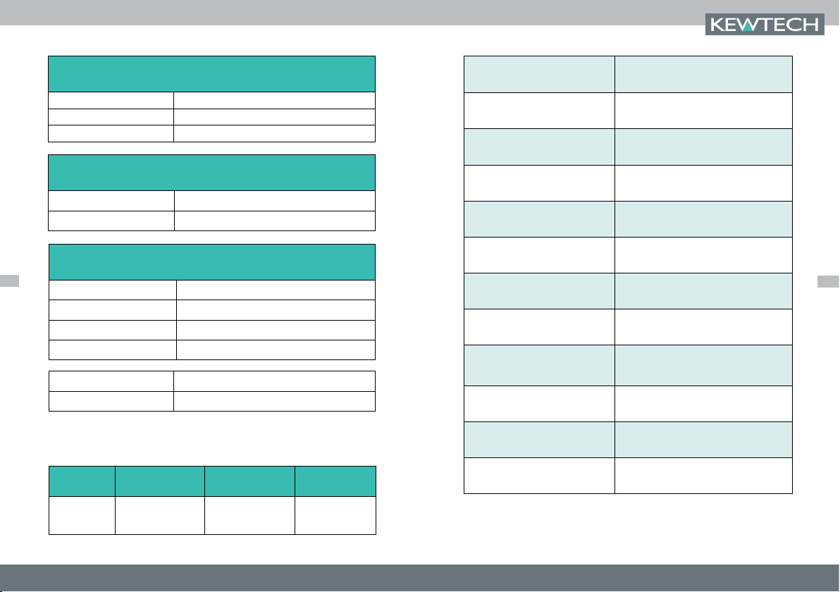
No Trip L-E Loop Test
(No trip L-E mode, 3 wire testing, Phase - Neutral - Earth all connected)
Range Accuracy
0.00 to 99.99 Ω ± (5% + 5 digits)
100.0 to 499.9 Ω ± (3% + 3 digits)
Hi I L-E Loop Test
(HI I L-E mode, 3 wire testing, Phase - Neutral - Earth all connected)
Auto Range Accuracy
0.00 to 500.0 Ω ± (3% + 3 digits)
Power supply 4 x AA LR6 Batteries
Battery life 50 hours
Overvoltage category
CAT III 500V
CAT IV 300V
Operating temperature 0 - 40ºC
Storage temperature -10 to 60ºC
Hi-Resolution, Hi I L-E / L-N Loop Test
10
(HI I L-E/L-N mode, 3 wire testing, Phase - Neutral - Earth all connected)
Range Accuracy
0.000 to 9.999 Ω + (3% + 30 mΩ)
10.00 to 99.99 Ω + (3% + 3 digits)
100.0 to 500.0 Ω + (3% + 3 digits)
Supply Voltage 195 - 260V (50 - 60 Hz)
Overprotection 440V
The following are details of the operating ranges for individual
functions compliant with the performance requirements of EN61557
Loop No Trip
Loop Hi-I
Measurement
Range
0.010 Ω - 500 Ω
0.01 Ω - 500 Ω
Operating Range
EN61557
1.04 Ω - 500 Ω
1.04 Ω - 500 Ω
Other
230 V 50 Hz
230 V 50 Hz
Operating humidity 80% @ 31ºC to 50% @ 40ºC
Safety compliance BSEN 61010-2-030:2010
EMC compliance BSEN 61326-2-2:2013
Performance standard
BSEN 61557-1:2007
BSEN 61557-3:2007
Probes GS38 compliant
Dimension (mm) 180mm x 85mm x 50mm
Weight (g) Approximately 450g
kewtechcorp.comkewtechcorp.com
11

For repair and calibration please return to us at :
Express Cal
Unit 2, Shaw Wood Business Park, Shaw Wood Way, Doncaster DN2 5TB
01302 761044 F: 01302 321993
expresscal@kewtechcorp.com
Kewtech Corporation Limited
Midas House, Unit 2b, Stones Courtyard, High Street, Chesham, Bucks HP5 1DE
01494 792212 F: 01494 791826
sales@kewtechcorp.com
kewtechcorp.com
 Loading...