

KEUCO Plan S, 52902 010000, Plan S Series, 52902 070000, 52904 070000 Mounting Instruction
...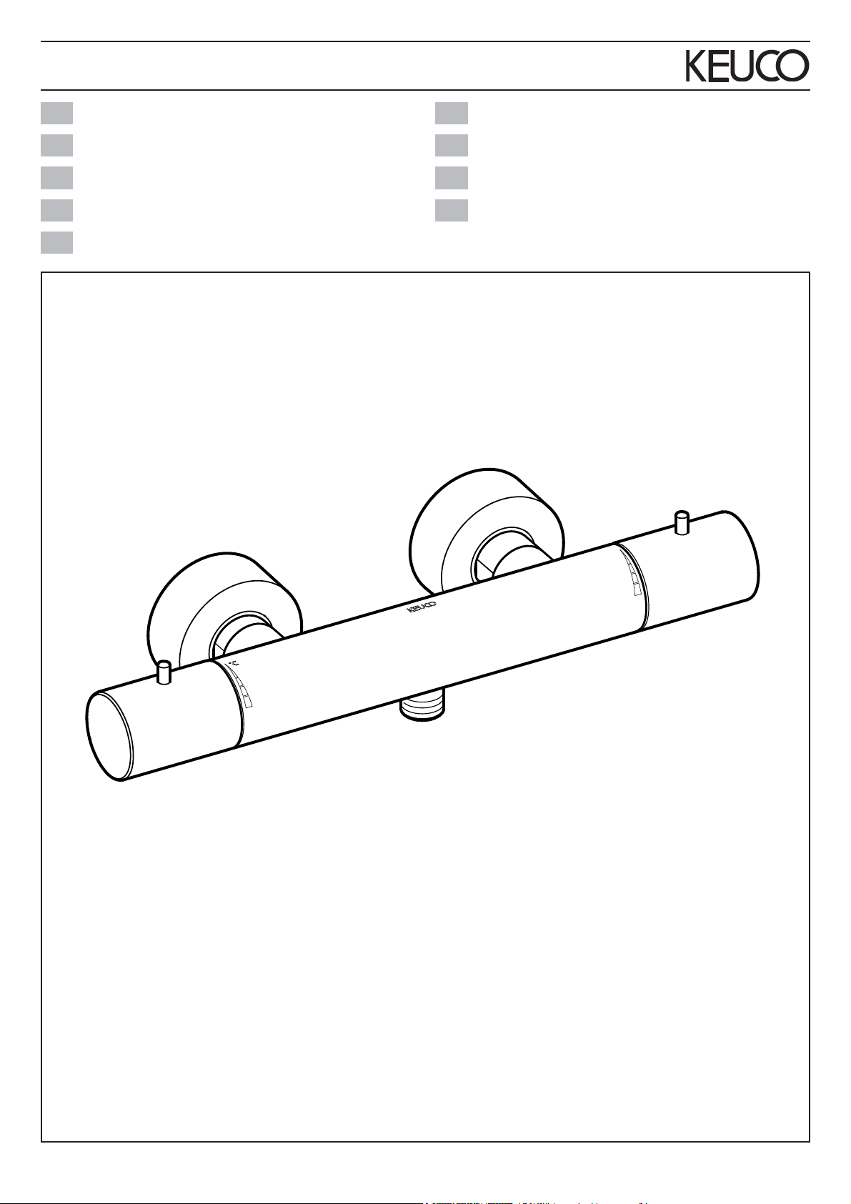
Plan S
Montageanleitung
DE
Mounting instruction
EN
Instrucciones de instalación
ES
Instructions d'installation
FR
Istruzioni per l'installazione
IT
Montagehandleiding
NL
Návod k instalaci
CS
Instrukcja montażu
PL
Инструкция по монтажу
RU
52924 010100
52924 070100
52924 170100
74109_000/05.2017
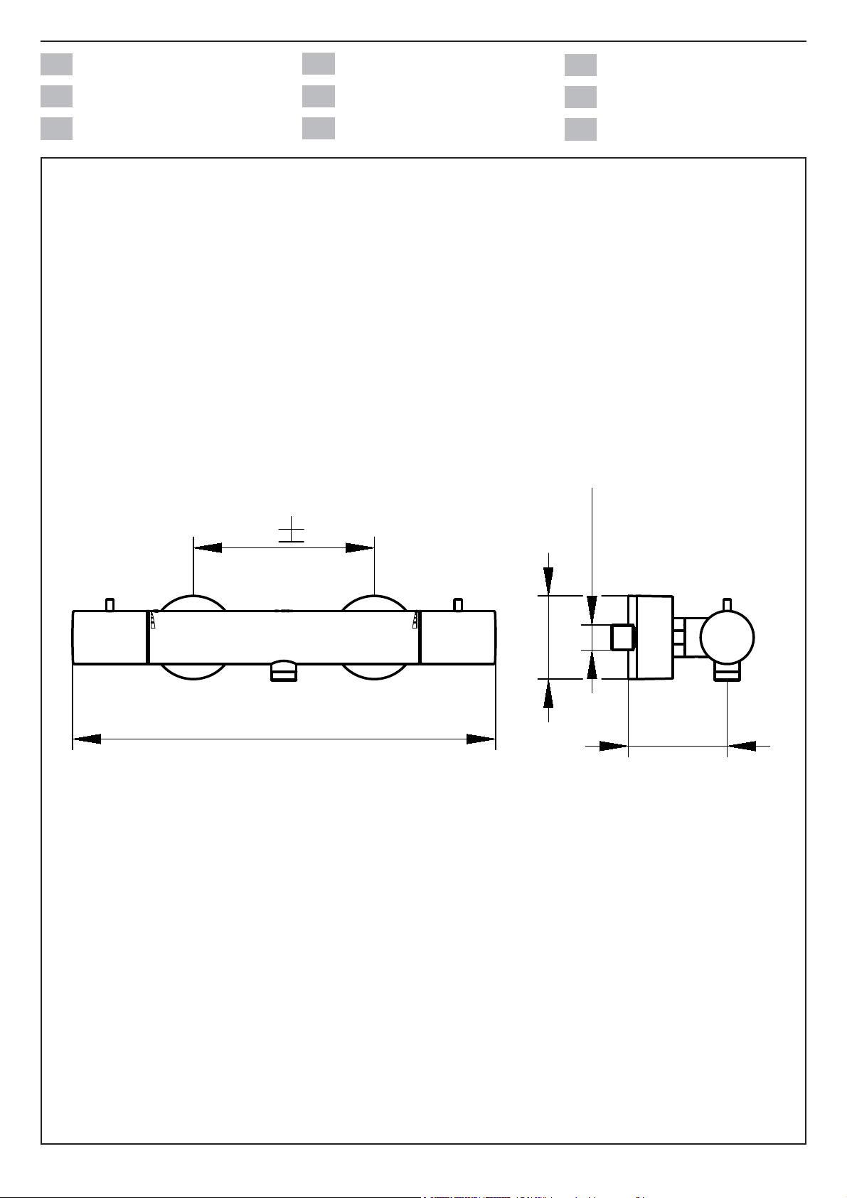
Einbaumaße
Einbaumaße
DE
DE
Mounting dimensions
Mounting dimensions
EN
EN
Dimensiones de montaje
Dimensiones de montaje
ES
ES
Dimensions de montage
Dimensions de montage
FR
FR
Dimensioni di montaggio
Dimensioni di montaggio
IT
IT
Montageafmetingen
Montageafmetingen
NL
NL
Montážní rozměry
Montážní rozměry
CS
CS
Wymiary montażowe
Wymiary montażowe
PL
PL
Установочные размеры
Установочные размеры
RU
RU
150 14
351
G1/2
Ø69
75-82
52924 XX0100
2
Wichtige Informationen, bitte unbedingt lesen! DE
Diese Anleitung ist für den Installateur zur Montage sowie für den Nutzer zur Bedienung und
Wartung des Produktes. Bitte nach der Installation an den Nutzer zur Verwahrung weitergeben.
Symbole und Bedeutung
Achtung! Warnung vor Personen- oder
Sachschaden.
Hinweis, Tipp oder Verweis
Korrekte Montage/Funktionsprüfung
Falsche Montage
Montagedetail beachten
Kaltwasser Warmwasser
Wasserfl uss Kein Wasserfl uss
Prüfen
?
Technische Daten
– Durchfl uss bei 3 bar Fließdruck: ca. 12 l/min
– Fließdruck: min. 0,5 bar/empfohlen 1-5 bar
– Betriebsdruck: max. 10 bar
– Prüfdruck: 16 bar
– Empfohlene Warmwassereingangstemperatur:
max. 65° C
– Wasseranschluss:
kalt = links
warm = rechts
Druckdifferenzen zwischen Kalt- und Warmwasserzulaufl eitungen vermeiden.
Bei Ruhedrücken über 5 bar Druckminderer
einbauen.
Einbaumaße, siehe Seite 2.
Installation, siehe ab Bild 1 auf Seite 12.
Trinkwasserleitungen vor und nach der Installation gründlich spülen (EN 806 und 1717 sowie
DIN 1988 beachten).
Anschlüsse mit hydraulischem Druck auf
Dichtheit prüfen.
Optional/Zubehör
Verwendungszweck
Brausemischer für die Verwendung in Badezimmer und WC. Betrieb mit Druckspeichern,
thermisch- und hydraulisch gesteuerten Durchlauferhitzern möglich. Betrieb mit drucklosen
Speichern (offenen Warmwasserbereitern) nicht
möglich!
Betrieb nur mit Wasser in Trinkwasserqualität.
Produkt ausschließlich zur Montage in Innen-
räumen geeignet!
Achtung! Installation nur in frostfreien Räumen.
Bedienung, siehe Bild 6 und 7 auf Seite 12 und 13
Temperaturbegrenzung einstellen, siehe Bild 8 auf
Seite 13
Wartung, siehe Bild 9 bis 11 auf Seite
Montage in umgekehrter Reihenfolge.
– Anzugsmoment Kartuschenmutter: 20-30 Nm
– Anzugsmoment Oberteil: <30 Nm
Hinweise zur Gewährleistung und Pfl ege sind
dem beiliegendem Pfl ege- und Garantiepass
zu entnehmen.
13
3
EN Important information, please read!
These instructions are for both the installer for
installation and the user for operation and maintenance of the product. After installation, please
hand them over to the user to keep.
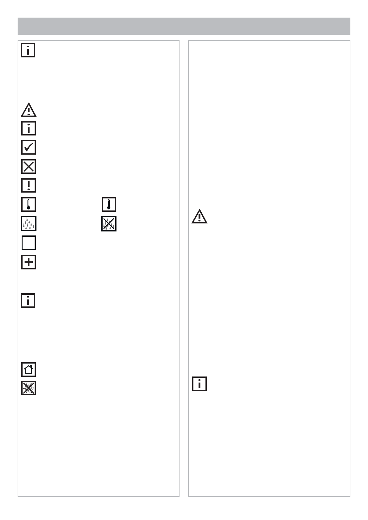
Symbols and explanations
Attention! Warning against bodily injury or
damage to property.
Note, tip or reference
Correct installation/test of functionality
Incorrect installation
Observe installation details
Cold water Hot water
Water fl ow No water fl ow
Test
?
Technical specifi cations
– Flow at 3 bar pressure: approx. 12 l/min
– Pressure: min. 0.5 bar/recommended 1-5 bar
– Operating pressure max. 10 bar
– Test pressure: 16 bar
– Recommended hot water inlet temperature:
max. 65°C
– Water connection:
cold = left
hot = right
Avoid pressure differences between the cold and
hot water feeds.
Install a pressure reducer for static pressures
above 5 bar.
Installation dimensions, refer to page 2
Installation, refer to picture 1 on page 12
Flush potable water pipes thoroughly before and
after installation (observe EN 806 and 1717, as
well as DIN 1988).
Test connections for leaks with water pressure.
Operation, refer to picture 6 and 7 on page 12 and 13
Optional/accessories
Intended use
Shower mixer for use in bathrooms and WCs.
Operation possible with pressure tanks and thermally and hydraulically controlled instantaneous
water heaters. Operation with unpressurised
tanks (open water heaters) is not possible!
Operation only with potable water.
Product is only suitable for installation indoors!
Attention! Only install in frost-free places.
Set temperature restriction, refer to picture 8 on
page 13
Servicing, refer to picture 9 to 11 on page 13
Assemble in reverse order.
– Cartridge nut torque: 20-30 Nm
– Headpart torque: <30 Nm
For spare parts with order numbers, refer to page 15.
For warranty and care information please refer
to the attached warranty and care instruc-
tions.
4
¡Información importante de lectura obligatoria! ES
Este manual está dirigido al instalador para el
montaje, así como al usuario para el manejo y
mantenimiento del producto. Por favor, después
de la instalación, este manual se debe entregar
al usuario para que lo conserve.
Símbolos y signifi cado
¡Atención! Advertencia de daños personales o
materiales.
Indicación, consejo o referencia
Montaje/comprobación de funcionamiento correctos
Montaje erróneo
Observar el detalle de montaje
Agua fría Agua caliente
Flujo de agua
Comprobar
?
Opcional/Accesorios
Uso previsto
Mezclador para ducha para la utilización en el
baño y en WC. Es posible el funcionamiento con
acumuladores de presión, calentadores de agua
instantáneos controlados térmica e hidráulicamente. ¡No es posible el funcionamiento con
acumuladores sin presión (calentadores de
agua abiertos)!
Funcionamiento sólo con agua en calidad de
agua potable.
¡Producto adecuado exclusivamente para el
montaje en interiores!
¡Atención! Instalación exclusivamente en espacios sin riesgo de heladas.
Ningún fl ujo de
agua
Datos técnicos
– Paso con una presión de caudal de 3 bares:
aprox. 12 l/min.
– Presión de caudal: mín. 0,5 bares /
recomendado 1-5 bares
– Presión de servicio: máx. 10 bares
– Presión de comprobación: 16 bares
– Temperatura de entrada de agua recomen-
dada: máx. 65° C
– Conexión de agua:
fría = a la izquierda
caliente = a la derecha
Evitar las diferencias de presión entre las
tuberías de agua fría y caliente.
En caso de presiones estáticas superiores a 5
bares, montar reductor de presión.
Medidas de montaje, véase página 2
Instalación, véase imagen 1 en la página 12
Lavar minuciosamente las tuberías de agua
potable antes y después de la instalación
(observar EN 806 y 1717).
Comprobar la estanqueidad de las conexiones
con presión hidráulica.
Manejo, véase imagen 6 y 7 en la página 12 y 13
Ajustar la limitación de temperatura, véase imagen 8
en la página 13
Mantenimiento, véase imágenes 9 a 11 en la
página 13
El montaje se efectúa en el orden inverso.
– Par de apriete de la tuerca de fi jación del
cartucho: 20-30 Nm
– Par de apriete de la montura: <30 Nm
Piezas de recambio con números de pedido, véase
página 15.
En el pasaporte de mantenimiento y garantía
adjunto encontrará indicaciones sobre la
garantía y el mantenimiento.
5

FR Informations importantes, à lire impérativement!
Ces instructions sont destinées à l'installateur,
pour effectuer le montage, et pour l'utilisateur,
pour utiliser le produit et procéder à sa
maintenance. Après l'installation, veuillez
remettre ces instructions à l'utilisateur pour qu'il
les conserve.
Symboles et leur signifi cation
Attention ! Mise en garde contre les dégâts de
personnes et les dégâts matériels.
Remarque, conseil ou renvoi
Montage correct/contrôle fonctionnel
Montage incorrect
Respecter le détail de montage
Eau froide Eau chaude
Débit d'eau Pas de débit d'eau
Caractéristiques techniques
– Débit à une pression d'écoulement de 3 bar :
env. 12 l/mn
– Pression d'écoulement :
min. 0,5 bar/pression conseillée 1-5 bar
– Pression de service : max. 10 bar
– Pression de contrôle : 16 bar
– Température d'entrée d'eau chaude conseillée :
max. 65° C
– Raccordement d'eau :
froide = à gauche
chaude = à droite
Éviter les différences de pression entre conduite
d'arrivée eau froide et conduite d'arrivée eau
chaude.
Pour des pressions de repos supérieures à 5 bar,
monter un détendeur.
Cotes d'encombrement, voir page 2
Installation, voir fi gure 1 à la page 12
Rincer soigneusement les conduites d'eau
potable avant et après l'installation (respecter les
normes EN 806 et 1717).
Vérifi er
?
Option/accessoires
Domaine d'utilisation
Mitigeur de douche pour utilisation dans la salle
de bains et les WC. Utilisation possible avec
accumulateurs de pression, réchauffeurs à circulation à commande thermique et hydraulique.
Utilisation avec accumulateurs sans pression
(chauffe-eau ouverts) impossible !
Utilisation seulement avec eau de qualité eau
potable..
Le produit ne convient que pour un montage à
l'intérieur !
Attention ! Installation uniquement dans des
pièces à l'abri du gel.
Vérifi er l'étanchéité des raccords à la pression
hydraulique.
Utilisation, voir fi gure 6 et 7 à la page 12 et 13
Régler la limitation de température,voir fi gure 8,
page 13
Maintenance, voir fi gures 9 à 11, page 13
Le montage s’effectue dans l’ordre inverse de la
dépose.
– Couple de serrage écrou de cartouche :
20-30 Nm
– Couple de serrage supérieur : <30 Nm
Pièces de rechange avec numéros de commande,
voir page 15.
Les consignes relatives à la garantie et à
l'entretien fi gurent sur la carte d'entretien et de
garantie jointe.
6

Informazioni importanti! Assicurarsi di leggerle! IT
Il presente manuale è indirizzato agli installatori
per il montaggio nonché agli utilizzatori per l’uso
e la manutenzione del prodotto. Consegnarlo
all’utilizzatore dopo l’installazione affi nché lo
custodisca.
Simboli e signifi cato
Attenzione! Pericolo di lesioni o danni materiali.
Avvertenza, consiglio o rimando
Montaggio corretto/verifi ca del funzionamento
Montaggio errato
Prestare attenzione al dettaglio di montaggio
Acqua fredda Acqua calda
Flusso d’acqua
Verifi care
?
Opzionale/accessorio
Nessun fl usso
d’acqua
Dati tecnici
– Portata con pressione di fl usso di 3 bar:
circa 12 l/min
– Pressione di fl usso:
min. 0,5 bar/raccomandati 1-5 bar
– Pressione di esercizio: max. 10 bar
– Pressione di prova: 16 bar
– Temperatura d’ingresso dell’acqua calda con-
sigliata:
max. 65°C
– Collegamento dell’acqua:
fredda = sinistra
calda= destra
Evitare differenze di pressione tra condotta di
mandata dell’acqua fredda e calda.
Per pressioni statiche superiori a 5 bar installare
un riduttore di pressione.
Ingombro, vedi pagina 2
Installazione, vedi dalla fi gura 1 a pagina 12
Prima e dopo l’installazione lavare con acqua
abbondante le condotte di acqua potabile
(osservare EN 806 e 1717).
Verifi care la tenuta degli attacchi con pressione
idraulica.
Scopo d’uso
Miscelatore per doccia per l’utilizzo in bagni
e WC. Possibilità di funzionamento con accumulatori di pressione, riscaldatori istantanei a
controllo termico o idraulico. Funzionamento con
accumulatori senza pressione (boiler con camera aperta) non possibile!
Funzionamento solo con acqua potabile.
Prodotto adatto esclusivamente per il montaggio
in ambienti interni!
Attenzione! Installazione solo in ambienti in
assenza di gelo.
Uso, vedi fi gura 6 e7 a pagina 12 e13
Regolazione della limitazione di temperatura, vedi
fi gura 8 a pagina 13
Manutenzione, vedi fi gura 9 - 11 a pagina 13
Eseguire il montaggio in ordine inverso.
– Coppia del dado della cartuccia: 20-30 Nm
– Coppia del parte superiore: <30 Nm
Ricambi con numero d’ordine, vedi pagina 15.
Indicazioni relative alla garanzia e al trattamento
vanno desunte dalla scheda allegata.
7

NL Belangrijke informatie, zorgvuldig doorlezen!
Deze handleiding is bestemd voor zowel de
installateur voor de montage alsook voor de
gebruiker voor het gebruik en het onderhoud
van het product. Gelieve na de installatie door te
geven aan de gebruiker om te bewaren.
Symbolen en betekenis
Opgepast! Gevaar voor letsel of schade.
Opmerking, tip of referentie
Correcte montage/werkingstest
Verkeerde montage
Montagedetails in acht nemen
Koud water Heet water
Waterstroom Geen waterstroom
Controleren
?
Technische gegevens
– Doorstroming bij 3 bar stromingsdruk:
ca. 12 l/min
– Stromingsdruk: min. 0,5 bar/aanbevolen 1-5 bar
– Bedrijfsdruk: max. 10 bar
– Testdruk: 16 bar
– Aanbevolen ingangstemperatuur heet water
max. 65° C
– Wateraansluiting:
koud = links
heet = rechts
Drukverschillen tussen toevoerleidingen voor
koud en heet water vermijden.
Bij statische druk van meer dan 5 bar
drukverlagers inbouwen.
Inbouwafmetingen, zie pagina 2
Installatie, zie vanaf afbeelding 1 op pagina 12
Drinkwaterleidingen voor en na de installatie
grondig spoelen (volgens EN 806 en 1717).
Aansluitingen met hydraulische druk controleren
op lekdichtheid.
Gebruik, zie afbeelding 6 en 7 op pagina 11 en 13
Optioneel/toebehoren
Bestemd gebruik
Douchemengkraan voor gebruik in badkamer en
wc. Bedrijf met drukluchtreservoirs, thermisch en
hydraulisch aangestuurde continuverwarmers
mogelijk. Bedrijf met drukloze reservoirs (open
heetwatertoestellen) niet mogelijk!
Gebruik uitsluitend met water van drinkwaterkwaliteit.
Het product mag alleen binnenshuis worden
gemonteerd!
Opgepast! Installatie alleen in vorstvrije ruimten.
Temperatuurgrens instellen, zie afbeelding 8 op
pagina 13
Onderhoud, zie afbeelding 9 - 12 op pagina 13
Montage in omgekeerde volgorde.
– Aandraaimoment moer voor cartouche:
20-30 Nm
– Aandraaimoment bovendeel: <30 Nm
Wisselstukken met bestelnummers, zie pagina 15.
Instructies voor de waarborg en het onderhoud
vindt u in de meegeleverde Onderhouds- en
garantiekaart.
8

Důležité informace, přečtěte si prosím pozorně! CS
Tento návod slouží instalatérům při montáži a
uživatelům při obsluze a údržbě produktu. Po
nainstalování ho předejte uživateli, aby si ho
mohl uschovat.
Symboly a význam
Pozor! Výstraha před zraněním a věcnými
škodami.
Upozornění, tip nebo odkaz
Správná montáž / kontrola funkčnosti
Nesprávná montáž
Při montáži dbejte na tento detail
Studená voda Teplá voda
Průtok vody Žádný průtok vody
Technické údaje
–Průtok při průtokovém tlaku 3 bary:
cca. 12 l/min
–Průtokový tlak: min. 0,5 bar/doporučeno 1-5 bar
– Provozní tlak: max. 10 bar
– Zkušební tlak: 16 bar
– Doporučená teplota vstupní teplé vody:
max. 65° C
–Přípojka vody:
studená = vlevo
teplá = vpravo
Vyvarujte se rozdílu tlaku mezi přívodním
potrubím teplé a studené vody.
U klidového tlaku na 5 barů nainstalujte redukční
ventil.
Montážní rozměry viz strana 2
Instalace viz obrázek 1 na straně 12
Potrubí na pitnou vodu před a po instalaci
důkladně vypláchněte (postupujte podle EN 806
a 1717).
Kontrola
?
Volitelná výbava / příslušenství
Účel použití
Sprchová směšovací armaturaí pro použití v
koupelnách a WC. Provoz s tlakovými zásobníky, tepelně a hydraulicky řízenými průtokovými
ohřívači možný. Provoz s beztlakými zásobníky
(otevřené ohřívače vody) není možný!
Provoz pouze s pitnou vodou.
Výrobek je vhodný výhradně k montáži ve
vnitřních prostorách!
Pozor! Instalace v prostorách, které
nepromrzají.
Těsnost přípojek zkontrolujte hydraulickým
tlakem.
Obsluha viz obrázek 6 a 7 na straně 11 a 13
Nastavení omezovače teploty, viz snímek 8 na
straně 13
Údržba, viz snímky 9 - 12 na straně 13
Montáž probíhá v obráceném pořadí.
– Utahovací moment matice kartuše: 20-30 Nm
– Utahovací moment horní díl: <30 Nm
Náhradní díly s objednacími čísly viz strany 15.
Pokyny týkající se záruky a péče najdete v přiloženém Návodu k údržbě a záručním listu.
9

PL Ważne informacje, proszę przeczytać uważnie!
Instrukcja przeznaczona jest dla instalatora,
zapewniając pomoc w zakresie montażu oraz dla
użytkownika, informując go o sposobie obsługi
i konserwacji produktu. Po instalacji należy
przekazać instrukcję użytkownikowi, aby ją u
siebie przechowywał.
Symbole i znaczenie
Uwaga! Ostrzeżenie przed szkodami
osobowymi i materialnymi.
Informacja, dobra rada lub odsyłacz
Właściwy montaż / kontrola funkcjonowania
Niewłaściwy montaż
Należy stosować się do danych, dotyczących
montażu
Woda zimna Woda gorąca
Strumień wody
Kontrola
?
Brak strumienia
wody
Dane techniczne
– Przepływ w przypadku ciśnienia hydraulicznego
3 bar: około 12 l/min
–Ciśnienie hydrauliczne:
min. 0,5 bar/zalecane 1-5 bar
–Ciśnienie robocze: maks. 10 bar
–Ciśnienie kontrolne: 16 bar
– Zalecana temperatura wody gorącej na wejściu:
maks. 65° C
– Przyłącze wody:
zimna = strona lewa
gorąca = strona prawa
Należy unikać różnic ciśnień w przewodach
doprowadzających ciepłą i zimną wodę.
W przypadku ciśnienia spoczynkowego ponad 5
bar należy zabudować reduktor ciśnienia.
Wymiary zabudowy, patrz strona 2
Instalacja, patrz rys. 1 na stronie 12
Przed instalacją i po instalacji należy gruntownie
przepłukać przewody, prowadzące wodę pitną
(należy stosować się do EN 806 i 1717).
Sprawdzić przyłącza ciśnieniem hydraulicznym w
celu potwierdzenia ich szczelności.
Opcje / Osprzęt
Przeznaczenie
Mieszacz prysznicowy do użycia w łazience i
WC. Możliwa eksploatacja przy współpracy ze
zbiornikami ciśnieniowymi lub podgrzewaczami przepływowymi, sterownymi termicznie lub
hydraulicznie. Eksploatacja przy współpracy ze
zbiornikami bezciśnieniowymi (otwartymi podgrzewaczami wody) nie jest możliwa!
Możliwa eksploatacja w instalacji wody, zapewniającej jakość typową dla wody pitnej.
Produkt przeznaczony jest wyłącznie do
montażu wewnątrz budynków!
Uwaga! Instalacja wyłącznie w pomieszczeniach,
w których temperatura nie spada poniżej zera.
Obsługa, patrz rys. 6 i 7 na stronie 12 i 13
Ustawienie ograniczenia temperatury, patrz rys. 8 na
stronie 13
Konserwacja, patrz rys. 9 do 11 na stronie 13
Montaż w odwrotnej kolejności.
– Moment obrotowy dokręcenia nakrętki głowicy:
20-30 Nm
– Moment obrotowy dokręcenia część głowicy:
<30 Nm
Części zamienne z numerami zamówienia, patrz
strona 15.
Informacje dotyczące gwarancji dostępne
są w dołączonej karcie pielęgnacyjno-
gwarancyjnej.
10

Важная информация, просим обязательно прочесть! RU
Данная инструкция содержит указания по
монтажу изделия для слесаря-сантехника
и указания по эксплуатации и техническому
обслуживанию изделия для пользователя.
После установки передайте инструкцию пользователю.
Символы и их значение
Внимание! Опасность физического и
материального ущерба.
Указание, совет или ссылка
Правильный монтаж / проверка
работоспособности
Неправильный монтаж
Важная информация по монтажу
Холодная вода Горячая вода
Водный поток
Нет водного
потока
Технические характеристики
– Пропускная способность при давлении
потока в 3 бар: около 12 л/мин
– Давление потока:
мин. 0,5 бар/рекомендуется 1-5 бар
– Рабочее давление: макс. 10 бар.
– Расчетное давление: 16 бар.
– Рекомендуемая входная температура
горячей воды: макс. 65° C
– Подключение воды:
холодная = слева
горячая = справа
Во избежание перепадов давления между
горячей и холодной водой
трубопровода.
В состоянии покоя свыше 5 бар устанавливать
редуктор давления.
Монтажные размеры, см. стр. 2
Установка, см. рис. 1 на стр. 12
Водопроводы питьевой воды до и после
установки тщательно промыть (EN 806
и 1717).
при подводе
Проверка
?
Опция/принадлежность
Назначение
Смеситель для душа для использования в
ванной комнате и туалете. Возможна эксплуатация гидроаккумулятора, термически и
гидравлически регулируемых прямоточных
нагревателей. Эксплуатация аккумулятора без
давления (открытые водонагреватели) невоз-
можна!
Использовать только воду питьевого качества.
Изделие предназначено исключительно для
монтажа внутри помещения!
Внимание! Устанавливать только в
непромерзающих помещениях.
Проверьте соединения с гидравлическим
давлением на герметичность.
Эксплуатация, см. рис. 6 и 7 на стр. 12 и 13
Установка ограничения температуры, см. Рисунок
8 на стр. 13
Техническое обслуживание, см. Рисунок 9 до 11 на
стр. 13
Монтаж производится в обратной
последовательности.
– Момент затяжки гайки картриджа: 20-30 Нм
– Момент затяжки кран-букса: <30 Нм
Запасные части с номерами для заказа, см. стр. 15.
Информацию о гарантии и указания по уходу
см. в прилагаемом паспорте по уходу и
гарантийному обслуживанию.
11

1
5
1
0mm
2
4
1
±
1.
2.
17mm
3
5
4
6
2.
3.
1.
12
2.
30mm
1.

7
8
1.
2.
9
11
10
17mm
27mm
13

14

DE
Ersatzteile
Liste de pièces
FR
Sada náhradních
CS
Spare parts
EN
Piezas de recambio
ES
NL
50100000412
Elenco delle parti
IT
Onderdelen
50100000046
50114010003
50114070003
50114170003
50100010233
50100070233
50100170233
Zestaw części
PL
Запчасти
RU
50100000236
50100010642
50100070642
50100170642
50100000231
50100000228
50100000232
50100010192
50100070192
50100170192
50100000194
50100000228
50100010642
50100070642
50100170642
52924 010100
52924 070100
52924 170100
15

DE
AT
CH
KEUCO GmbH Co. KG
Oesestraße 36
D-58675 Hemer
Telefon: +49 2372 904-0
E-Mail: info@keuco.de
EN
KEUCO UK Ltd
Amersham House
Mill Street
GB-Berkhamsted
Phone: +44 1 442865220
E-Mail: admin@keuco.co.uk
RU
KEUCO GmbH Co. KG
Представительство в России
Космодамианская набережная ,
дом 4 / 22, корпус Б
115035 Москва
Электронная почта:
offi ce-russia@keuco.com
KEUCO GmbH
Söllheimerstraße 16
Objekt 6c
A-5020 Salzburg
Telefon: +43 662 4540560
E-Mail: offi ce@keuco.at
FR
KEUCO SARL
5, Rue du Martelberg
F-67700 Monswiller
Téléphone: +33 3 88700200
E-Mail: buerau@keuco.fr
US
KEUCO Management Inc.
384-A Clinton Street
USA-Costa Mesa CA 92626
Phone: +1 714 708-2937
E-Mail: offi ce-usa@keuco.com
KEUCO AG
Winkelweg 3
CH-5702 Niederlenz
Telefon: +41 62 8880020
E-Mail: info@keuco.ch
NL
KEUCO GmbH Co. KG
Kantoor Nederland
Selma Lagerlofweg 69
NL-3069 BT-Rotterdam
Telefoon: +31 10 4423344
E-Mail: info@keuco.nl
 Loading...