

Page 1
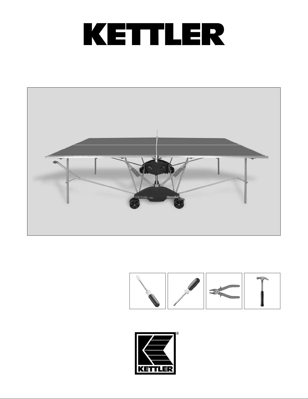
Match 5.0 Table Tennis Table
Printed on recycled paper.
Made in Germany
Picture Similar
KETTLER®International Inc. • 1355 London Bridge Road • Virginia Beach, VA 23453 USA
www.kettlerusa.com
info@kettlerusa.com
Adult Assembly Required
Please do not return this product to
the store. Contact KETTLER® for
parts and service: call toll free
866.804.0440 or send email to
parts@kettlerusa.com. Please visit
our web site www.kettlerusa.com to
view a video demonstration of
product assembly.
®
Models 7136-000-500 & 7176-000-090-500
Page 2

Note on Safety
All KETTLER®products are designed in accordance with the latest safety regulations and undergo a constant process of quality
control during manufacturing. The knowledge gained in this process is used to constantly improve and develop our products. In
order to offer our customers the very best in product quality, we reserve the right to make technical changes at any time. In spite
of this, should you have any cause for complaint, please contact KETTLER
®
.
Before assembling or using the table tennis table, please read the following instructions carefully. They contain important information for
use and maintenance of the equipment as well as for your personal safety. Keep these instructions in a safe place for maintenance
purposes or for ordering spare parts.
• The table tennis table should be used only for its
intended purpose, i.e. for playing with suitable table
tennis racquets and balls.
• All other uses are prohibited and may be dangerous.
The manufacturer cannot be held liable for damage
or injury caused by improper use of the table.
• Damaged or worn components may endanger your
safety or shorten the lifespan of the table tennis
table. Replace worn or damaged components
immediately and remove the table from use until this
has been done. Use only spare parts manufactured
by KETTLER
®
.
• The table tennis table complies with all safety
regulations. Incorrect repairs, alterations to the
design (removal of original parts, addition of other
components etc.) may endanger the safety of the
user.
• Instruct other persons (in particular children) using
the table in its correct use, and draw their attention
to any potential source of danger, especially when
setting up or dismantling the table.
• Caution: During assembly, keep all items out of
children’s reach (choking hazard - contains small
parts).
• When setting up or dismantling the table, stay clear
of its folding radius.
• When folded up, the table tennis table presents a
large surface to the wind. For this reason, ensure
that it is stored in a sheltered position.
• The table tennis table may be pushed only in the
transport position otherwise there is a risk of injury.
• The unit complies with the standard
EN 4468–1:2004.
• Regularly check all screws, bolts etc. to ensure they
are in good condition.
• Warning: Children should not attempt to fold/unfold
table. May result in injury
Handling the Equipment
• Do not use the table tennis table until it has been
fully and correctly assembled and checked.
• Ensure that indoor table tennis tables are not
exposed to dampness or rain. Keep them well
away from direct sources of heat. Should the
surface become warped, lay the table on a level
surface for a few days.
• Set the table up on a level surface.
• Do not cover it with a tarp, which can result in
condensation forming. We recommend the
weatherproof KETTLER
®
cover, part number
7032-400. Cover should only be used when table
is in folded position.
• For practicing without a partner, the table halves can
be folded up individually.
• Do not use corrosive or abrasive materials to clean
the equipment. Ensure that such materials are not
allowed to pollute the environment. In most cases, a
slightly dampened cloth is sufficient.
• Waste Disposal: KETTLER
®
products are
recyclable. At the end of its useful life, please
dispose of correctly and safely complying with your
local facilities and guidelines.
• Store table in folded position when not in use.
Before Assembly
2
Page 3
Before Assembly (continued)
General Assembly Instructions
• The equipment must be assembled with care by two
adults.
• Separate all the parts including the hardware.
Compare quantities with the package contents
section and that all items are undamaged. If there
are any problems, please contact KETTLER
®
.
• Before assembling the equipment, study the
drawings and photos carefully then assemble in the
order shown.
• Please note that there is always a danger of injury
when working with tools or doing manual work.
Therefore, please be careful during assembly.
• Ensure that your working area is free of possible
sources of danger, for example don’t leave any tools
lying around. Always dispose of packaging material
in such a way that it may not cause any danger.
There is always a risk of suffocation if children play
with plastic bags!
• The fastening items required for each assembly step
are shown at the beginning of the step. Use the
fastening items exactly as instructed.
• Bolt all the parts together loosely at first, and check
that they have been assembled correctly. Then use
spanner for final tightening. Then check that all
screw connections have been tightened firmly.
• For technical reasons, we reserve the right to carry
out preliminary assembly work (e.g. addition of
tubing plugs).
• Please keep original packaging, so that it may be
used for transport at a later date, if necessary.
Goods may only be returned after prior arrangement
and in packaging that is safe for transportation ( in
the original box if possible). It is important to provide
a detailed defect description/damage report.
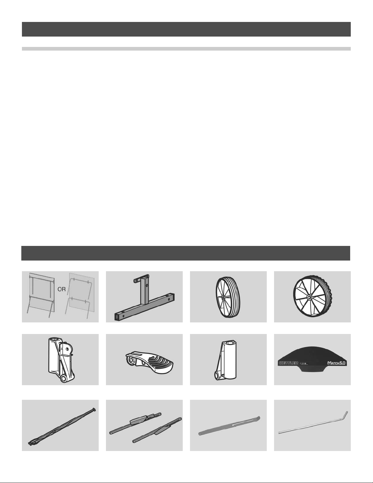
Package Contents
7176 7136
Number Included - 2 Number Included - 2 Number Incl - 4 non locking Number Incl - 4 locking
Number Included - 2 Number Included - 2 Number Included - 2 Number Included - 2
Number Included - 2 Number Included - 2 pairs Number Included - 2 Number Included - 4
3
Page 4
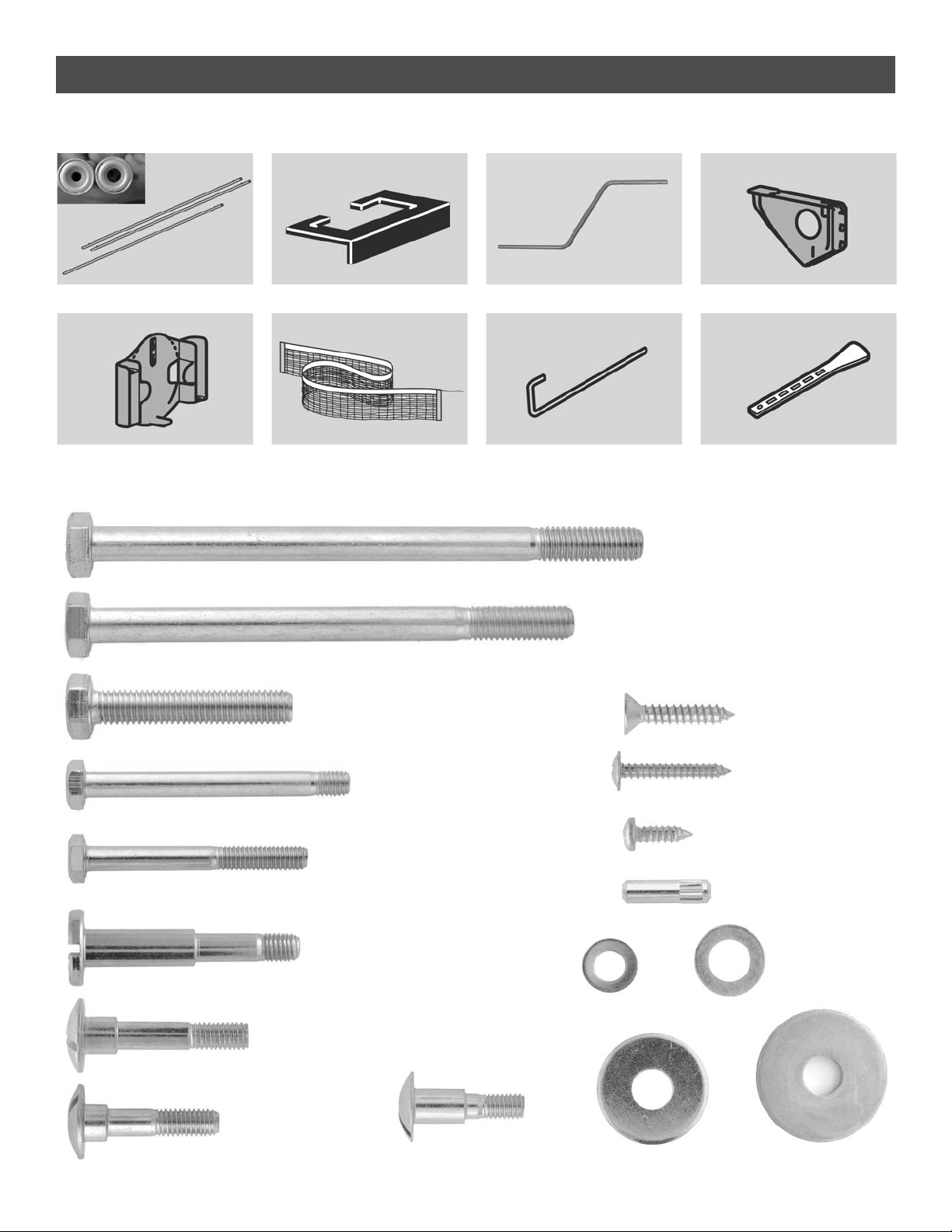
Items below are shown at actual size
Number Incl. - 1-6mm, 2-8mm Number Incl. - 2 (outdoor only) Number Included - 2 Number Included - 2
Number Included - 1 Number Included - 1 Number Included - 2 Number Included - 2
Number Included - 4
m8x125
Package Contents (continued)
Number Included - 4
m8x110
Number Included - 4
m8x45
Number Included - 4
m6x60
Number Included - 4
m6x49
Number Included - 2
m6x37
Number Included - 2
m6x30
Number Included - 4
m6x25
Number Included - 6
3.9x25
Number Included - 8
3.9x13
Number Included - 2
4.8x25
Number Included - 2
Number Included - 26
dia 12x6
Number Included - 28
dia 16x8
Number Included - 4
dia 30x8
Number Included - 4
dia 25x8
4
Number Included - 4
m6x50
Page 5
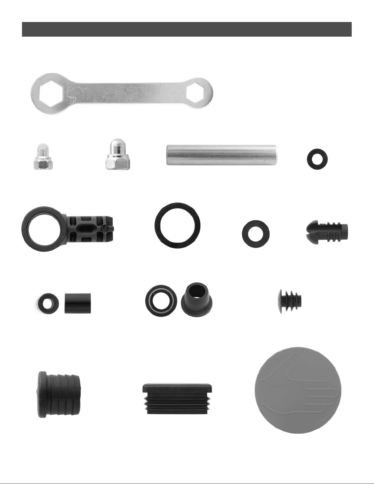
Package Contents (continued)
Items below are shown at actual size
Number Included - 18
m6
Number Included - 2
Number Included - 8
m8
Number Included - 8
Number Included - 4 Number Included - 8
m12x6x3
Number Included - 4
m26x19x6
Number Included - 2
m16x8x3
Number Included - 2
Number Included - 4
m12x6x15
Number Included - 8
Number Included - 2
Number Included - 2
Number Included - 4 Number Included - 4
5
Page 6
Assembly
Begin the assembly of your table by carefully removing
the plastic wrap and all of the loose contents. Separate
the two table tops by removing the four plastic corner
protectors and the plastic side strips.
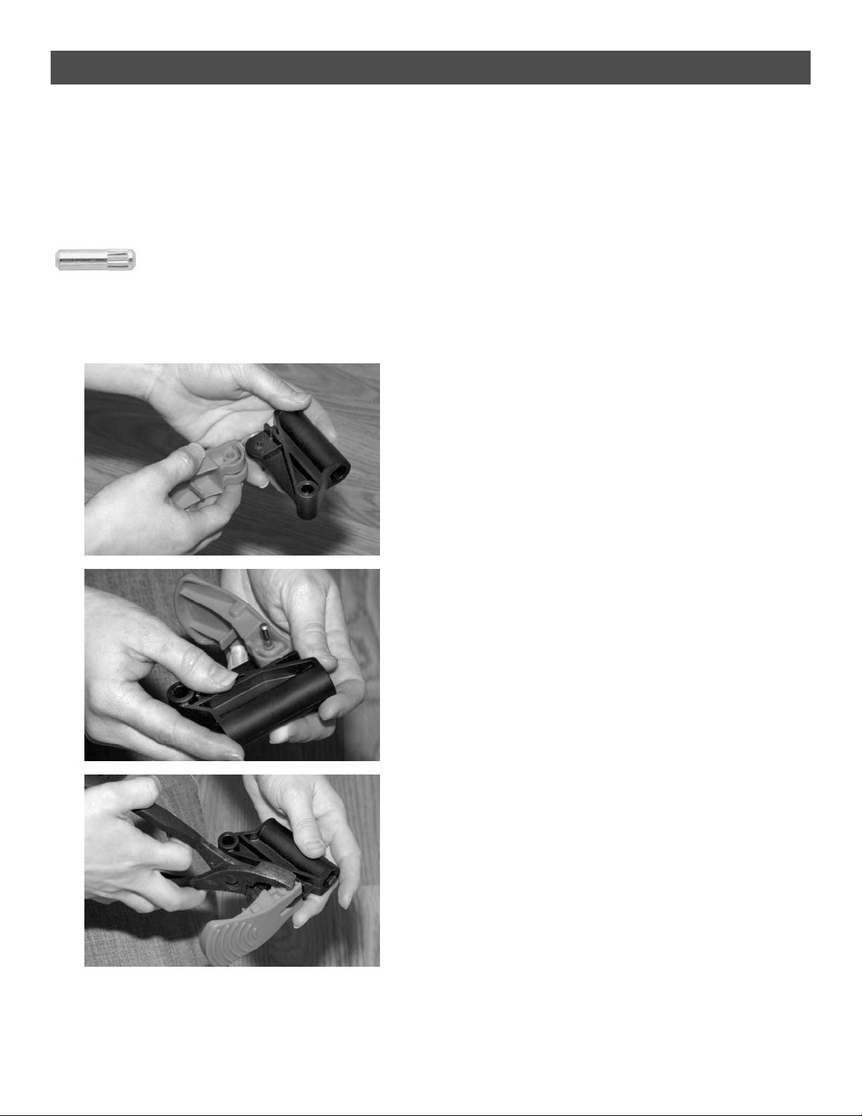
Step 1
2 Required
Align footlock with stemtube.
Insert drift pin. There are two footlocks and
stemtubes. Assemble both as shown.
A
B
C
6
Page 7
Assembly
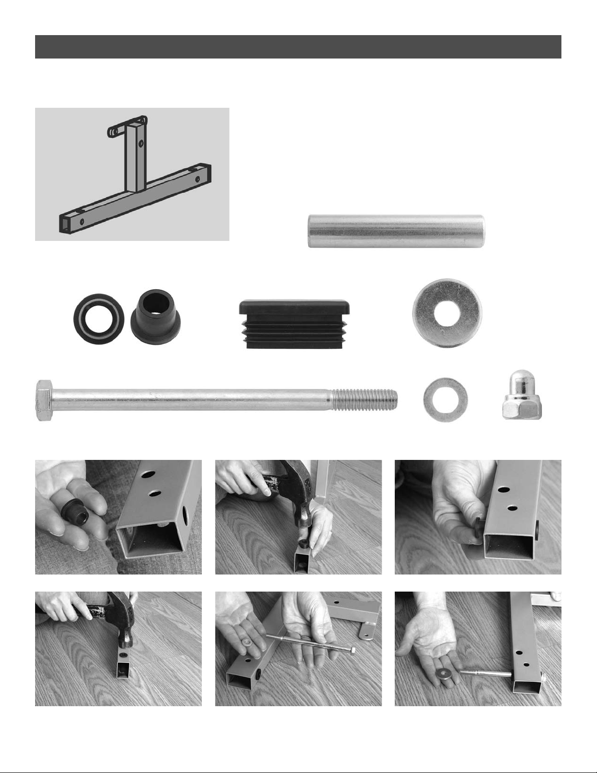
Step 2
A B C
D E F
4 Required
4 Required
m8
8 Required
dia 16x8
4 Required
m8x125
4 Required
dia 25x8
8 Required
End view and perspective view
4 Required
Paying attention to position of wheelbase, assemble
the stemtubes to base in order shown.
Insert endcaps.
Assemble two wheelbase assemblies.
7
Page 8
J K L
Assembly
Step 2 (continued)
G H I
Photo K shows the non locking stemtube being
installed. Step E to step J are the same for the locking
and non locking stemtube.
8
Page 9
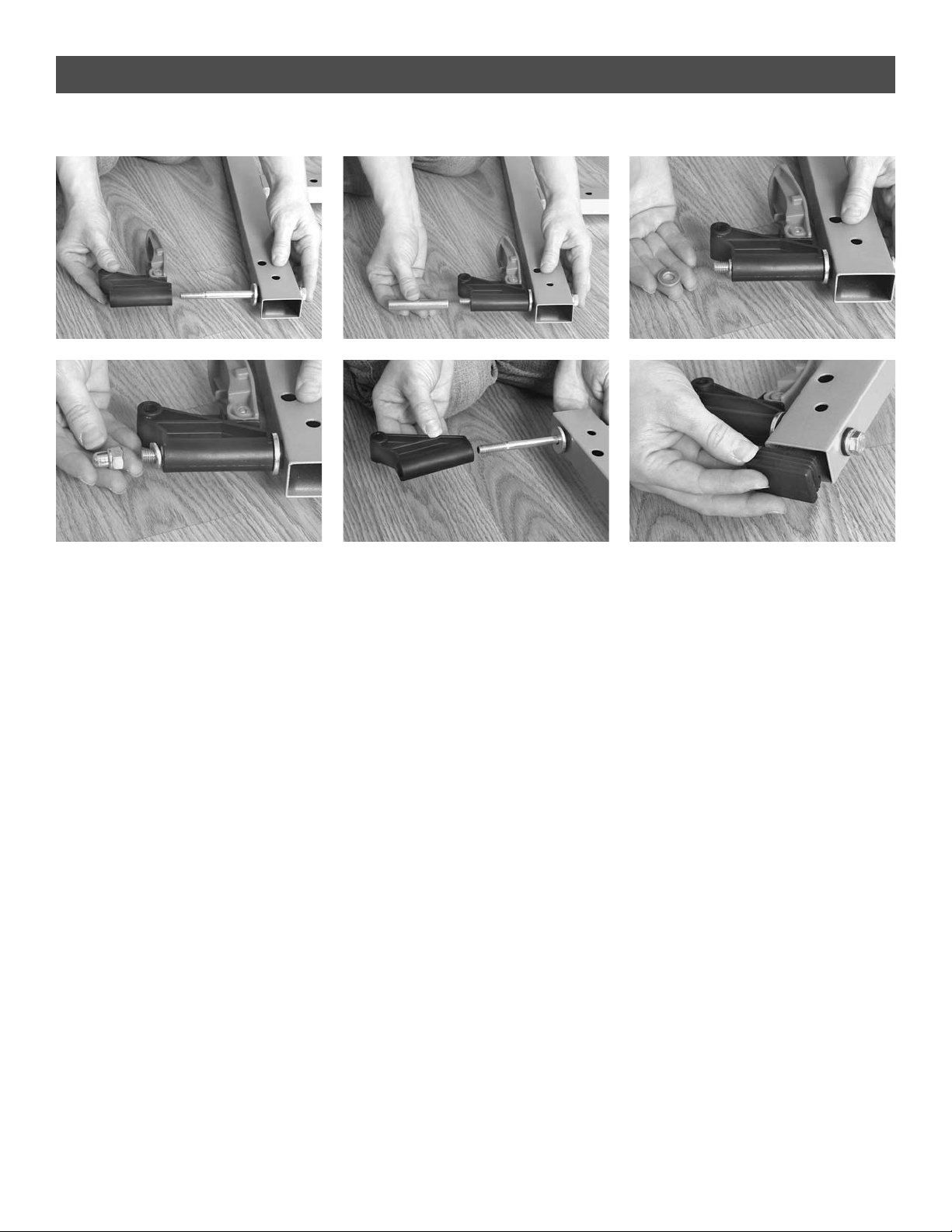
Step 3
Assembly
Install non-locking wheels.
Do not over torque; wheels should roll smoothly.
Install non-locking wheels on both wheelbase
assemblies.
A B C
D E
2 Required
m8x110
8 Required
dia 16x8
2 Required
8m
9
Page 10

Step 4
Assembly
Install locking wheels.
The grooves of wheels should face inward.
Again, do not over torque; wheels should roll smoothly.
Push down foot lock to lock the wheels.Install non-locking
wheels on both wheelbase assemblies.
A C
D
E
2 Required
m8x110
8 Required
dia 16x8
2 Required
m8
10
B
Page 11

Assembly
Step 5
Paying attention to position of wheelbase, snap alignment
struts into place.
Bolt locking struts to base. Bolt the locking strut with
thumb latch to the same side as locking wheels. Bolt strut
without latch to the side of non-locking wheels.
Assemble two identical wheelbase assemblies with wheels
and struts.
A B C
D E F
G H I
4 Required
m6x25
4 Required
dia 12x6
4 Required
m6
11
Page 12

Assembly
Step 6
Bolt one M8 crossbar between each wheelbase. This
crossbar is being assembled temporarily to create a
support base and will be removed at a later step.
For outdoor tables only: slide the shimpad onto wheelbase
(steps B, C, and D).
The assembly thus far should match photo E.
A B C
D E
M8 threads
M6 threads
12
2 Required
m8x45
Page 13

Assembly
Step 7
Insert endcap into the bottom of netpost bar.
Using M6 crossbar, assemble crossbar and netpost bars
to alignment struts.
The netpost bar installation is repeated on the other
wheelbase assembly. Fastener quantities include
installation on both wheelbase assemblies.
The assembly thus far should match photo G.
A B C
D E F
2 Required
G
6 Required
dia 12x6
2 Required
m6
13
4 Required
m6x50
Page 14

Assembly
Step 8
Screw eyelets to four Jbars.
Assemble safety levers to two of the Jbars.
Slide handgrip onto safety lever.
Note the orientation of the slot in the safety
lever and the Jbar as shown in photo E.
4 Required
dia 12x6
2 Required
m6
4 Required
2 Required
m6x30
2 Required
A B C
D E F
G
4 Required
3.9x13
note position
14
Page 15

Assembly
Step 9
Screw eyelets to support leg on table-top half.
Repeat for second table-top half.
4 Required
A B C
4 Required
3.9x13
Support Leg
15
Page 16

A B C
D
Step 10
Important: have two people complete steps 10-12. With assistance, lift one
table top onto the wheelbase; the legs will be facing outward. Have one
person support the top while it is resting on the base while the other
completes assembly.
Assemble crossbar to Jbars and support leg in the order shown. Note: a
Jbar with safety lever should be assembled on the right side (side with non
locking wheels) and a Jbar without lever on the left side (side with locking
wheels). The support leg is always assembled closest to the wheelbase. You
may need to lower table slightly to line up the bolt holes. Do not fully tighten
the bolts until both ends are assembled.
Assembly
2 Required
m8x45
2 Required
dia 16x8
2 Required
m26x19x6
2 Required
dia 30x8
E
F
G
16
Jbar
Support Leg
Jbar
Jbar
Support Leg
Jbar
Support Leg
Wheelbase
Page 17

A B C
D
Step 11
Raise safety lever up straight. Bolt the safety lever to leg.
Bolt the Jbars to leg.
Insert footcaps.
E F
Assembly
1 Required
m6x37
2 Required
dia 12x6
3 Required
m6
1 Required
m 16x8x3
G H I
2 Required
m6x60
4 Required
m 12x6x3
End view and side view shown - 2 Required
m12x6x15
2 Required
17
m 16x8x3
m 12x6x3
Leg
Page 18

Step 11 continued
Assembly
J K
L
Leg
Step 12
Bolt locking struts to support leg.
A
B C D
E F
G
2 Required
m6x49
2 Required
m6
4 Required
m12x6
18
Now, remove the temporary crossbar
assembled in step 6. Carry out steps
10-12 again for the other side.
Page 19

Assembly
19
A B
C
D
To properly open table into playing position: lock wheels (H), push the
thumb latch down on the left locking strut. Squeeze the strut on the right
side and lower table into playing position. Support the table as you
lower it; never allow it to drop down.
Open Table Top to Complete Assembly
Page 20

A C
D
Step 13
Slide net post onto netpost bar and screw into place.
Insert guide plug.
Repeat on other side of table.
Assembly
2 Required
4.8x25
2 Required
A B
Step 14
Attach ball/racquet holder to netpost.
B
20
Page 21

A B
Step 15
Screw sideshroud into place.
Repeat installation of second shroud on opposite side
wheelbase assembly.
Assembly
6 Required
3.9x25
21
3 Screws
Page 22

Assembly
Net Assembly
Net assembly:
Slide Jpin through net.. Place Jpin in designated slots. Tie
string to tension tab. Place string in slots over Jpin and net
post. Adjust net tension by adjusting tension tab.
Remove protective plastic film from table surface.
A B C
D
22
Page 23

Assembly
23
Folding Table
Folding Table:
To properly fold the table, lock the wheels, press the safety
lever up and lift top. Once the top is halfway up you can
release lever and continue to fold the top.
A B C
Remove Film
Remove protective plastic
film from table surface.
Page 24

THERE ARE NO WARRANTIES, EXPRESSED OR IMPLIED, MADE BY EITHER THE DISTRIBUTOR OR THE
MANUFACTURER ON KETTLER®PRODUCTS, EXCEPT THE MANUFACTURER’S LIMITED WARRANTY AGAINST
DEFECTS IN MATERIAL SET OUT BELOW:
This KETTLER®Limited Warranty applies to products sold through the KETTLER®Authorized Dealer Network to the
original retail purchaser and authenticated by proof of purchase from a retailer located in the United States. Any
shipments made under this warranty will be shipped to the United States only. Any shipment outside of the United States
will be at the sole cost of the customer. This KETTLER®Limited Warranty is a manufacturer’s warranty and is not
changed or modified by additional warranties extended by individual retailers at the point of sale. Manufacturer warrants
this product to be free from defects in material at the time of the product’s tender of delivery for a period of 3 years for
residential use and 1 year for commercial use. This Limited Warranty is not transferable and does not cover normal wear
and tear (including, but not limited to, damage and wear to tires, power shocks, drive belts and other non-durable parts).
The liability of the manufacturer under this Limited Warranty shall not include any liability for direct, indirect, or
consequential damages resulting from the defect. This Limited Warranty is void if the product is damaged by accident,
unreasonable use, improper service, failure to follow instructions provided, modification from its original state, or other
causes determined not arising out of defects in material.
This warranty gives you specific legal rights. Should this product become defective due to material within the warranty
period, contact KETTLER®Parts & Service Dept. by phone at 866.804.0440, fax at 757.563.9273, or e-mail at
parts@kettlerusa.com.
THIS LIMITED WARRANTY IS EXPRESSLY IN LIEU OF ANY OTHER WARRANTIES, EXPRESSED OR IMPLIED,
INCLUDING ANY IMPLIED WARRANTY OF MERCHANTABILITY OR FITNESS FOR A PARTICULAR PURPOSE,
AND OF ANY OTHER OBLIGATIONS OR LIABILITY ON THE PART OF THE MANUFACTURER. KETTLER
®
NEITHER ASSUMES NOR AUTHORIZES ANY OTHER PERSON TO ASSUME FOR IT ANY OTHER LIABILITY IN
CONNECTION WITH SUCH PRODUCTS.
Limited Warranty
24
Page 25

25
Ordering Spare Parts
When ordering spare parts, always state the full model number, spare part number, the quantity required and the serial number.
Example order: Model 7136-500/spare part number 70130761/qty 1/serial number…
Important: Spare part prices do not include fastening materials; if fastening material (bolts, nuts, washers, etc.) is required, this should be clearly stated on the order
by adding the words “with fastening material.”
Contact: KETTLER®International Inc., 1355 London Bridge Road, Virginia Beach, VA 23453 USA
Online: www.kettlerusa.com • E-mail: info@kettlerusa.com • For parts/service: call 866-804-0440 or e-mail parts@kettlerusa.com
Limited Warranty
Serial Number
Page 26

12
1
25
13
17
4
4
7
2
3
23
25
22
8
10
11
19
29
28
30
32
27
15
20
21
31
25
12
1
25
33
33
13
17
6
5
2
3
7
23
9
37
342635
36
38
Spare Parts
26
Page 27

Spare Parts
Spare Part Number Spare Part Number
Number for 7136-500 for 7176-500
Number Description Required Indoor Outdoor
1 Top 2 94130117 94130125
2 Leg 2 94111138 94111129
3 Footcap 4 70130540 70130540
4 Clamp (outdoor table) 8 10128028
5 Clamp 25mm (indoor table) 4 94110341
6 Clamp 18mm (indoor table) 4 94110192
7 Support Leg 2 94111139 94111130
8 Wheelbase 2 94111142 94111142
9 Stemtube for non-locking wheel (3437) 2 70130812 70130812
10 Locking Strut with thumb latch 2 94111137 94111137
11 Locking Strut without thumb latch 2 94111136 94111136
12 Safety Lever 2 94111120 94111120
13 Crossbar M8 2 94111055 94111055
15 Endcap 40x25mm 4 10100009 10100009
17 Handgrip 2 70130532 70130532
18 Hardware Bag (not illustrated) 1 94180323 94180323
19 Shimpad (pair) (outdoor table) 1 94180271
20 Net 1 94180274 94180274
21 Tension Tab 2 10128002 10128002
22 Alignment Strut 2 70130604 70130604
23 Jbar 4 94111132 94111132
25 Eyelet 8 70130830 70130830
26 Bushing 8 10116011 10116011
27 Sideshroud 2 70115017 70115017
28 Netpost Bar 2 94111080 94111080
29 Netpost 2 70130518 70130518
30 Ball and Racquet Holder 1 70130522 70130522
31 Guide plug (4439) 2 70130519 70130519
32 Endcap 2 10100096 10100096
33 Washer 26x19x6 4 10107067 10107067
34 Footlock (3507) 2 70130816 70130816
35 Non-locking Wheel 4 70130762 70130762
36 Locking Wheel 4 70130761 70130761
37 Stemtube for locking wheel (3508) 2 70130815 70130815
38 Crossbar M6 1 94111056 94111056
Spare Part Number Spare Part Number
Number for 7136-000 for 7176-000 & -090
Number Description Required Indoor Outdoor
1 Top 2 94130098 94130003
27
Page 28

©2011 KETTLER®All rights reserved. No part of this manual may be
reproduced, stored in a retrieval system, or transmitted in any form, or by
any means, such as electronic, mechanical, photocopying or otherwise,
without the prior written permission of KETTLER®.
KETTLER®International Inc., 1355 London Bridge Road, Virginia Beach, VA 23453 USA
www.kettlerusa.com • E-mail: info@kettlerusa.com
For parts/service: call 866-804-0440 or e-mail parts@kettlerusa.com
Docu 7.05.11
 Loading...