

Page 1

Wood Moisture Tester MT-700
Operating manual
Page 2

Wood Moisture Tester Safety Precautions
Injury or damage to property may result if proper safety procedures are not followed when using the wood moisture
tester.
• Be sure to carefully follow all safety precautions.
Carefully read operating manual.
• Do not use the unit if it is not functioning properly.
Immediately contact our service representative if the unit malfunctions or does not operate properly.
• Meaning of Warning Indications.
The symbols indicated below are used in the operating manual and on the unit itself in order to prevent accidents
due to misuse of the product.These symbols have the following meanings:
This symbol indicates information important for the understand in order to safely operate the product.
Caution
Page 3

CONTENTS
1. Features............................................................................ 2
2. Specifications.................................................................... 3
3. Part Names ....................................................................... 4
4. Display and Keypad .......................................................... 5
5. Directions .......................................................................... 6
5-1. Before Measuring ................................................... 6
5-2. Measurement Method............................................. 7
5-3. Displaying the average value................................. 10
5-4. Continuous Measurement ..................................... 11
5-5. Performing Moisture Content Bias Adjustment ..... 12
5-6. How to set an alarm value ..................................... 13
6. Error Code Display...........................................................14
7. Applications and Ranges ................................................. 16
Page 4

2
1. F eatures
1. Sixteen wood groups can be measured.
2. The wood group number(HARD:01-09,SOFT:10-16) is displayed.
3. When inactive, the unit will automatically power off after approximately five minutes.
4. When the moisture content exceeds the set upper value, a buzzer sounds.
5. The moisture content can be bias-adjusted for each wood group to correlate with local standards.
Page 5

3
2. Specifications
Measuring Principle : Electrical Resistance
Applications : Wood
Measuring Range : 5 to 40% (Depends on wood group)
Functions : Average
Auto power off (5minute)
Bias Adjustment (-9.9 ~ +9.9%)
Upper limit alarm setting
Operating Temperature : 0 to 40˚C
Display : LCD
Power Supply : Battery (1.5V, size”AA”alkaline ,6pcs)
Dimensions : 110(W) x 210(D) x 50(H) mm
Weight : 500g
Accessories : Needle probe (1), Spare needle (10), Conductive rubber (2), Wrench (1),
Shoulder strap (1), Battery (1.5V, LR6) (6), Calibration List (2),
Operating Manual (1), Carryingcase (1
)
Page 6
4
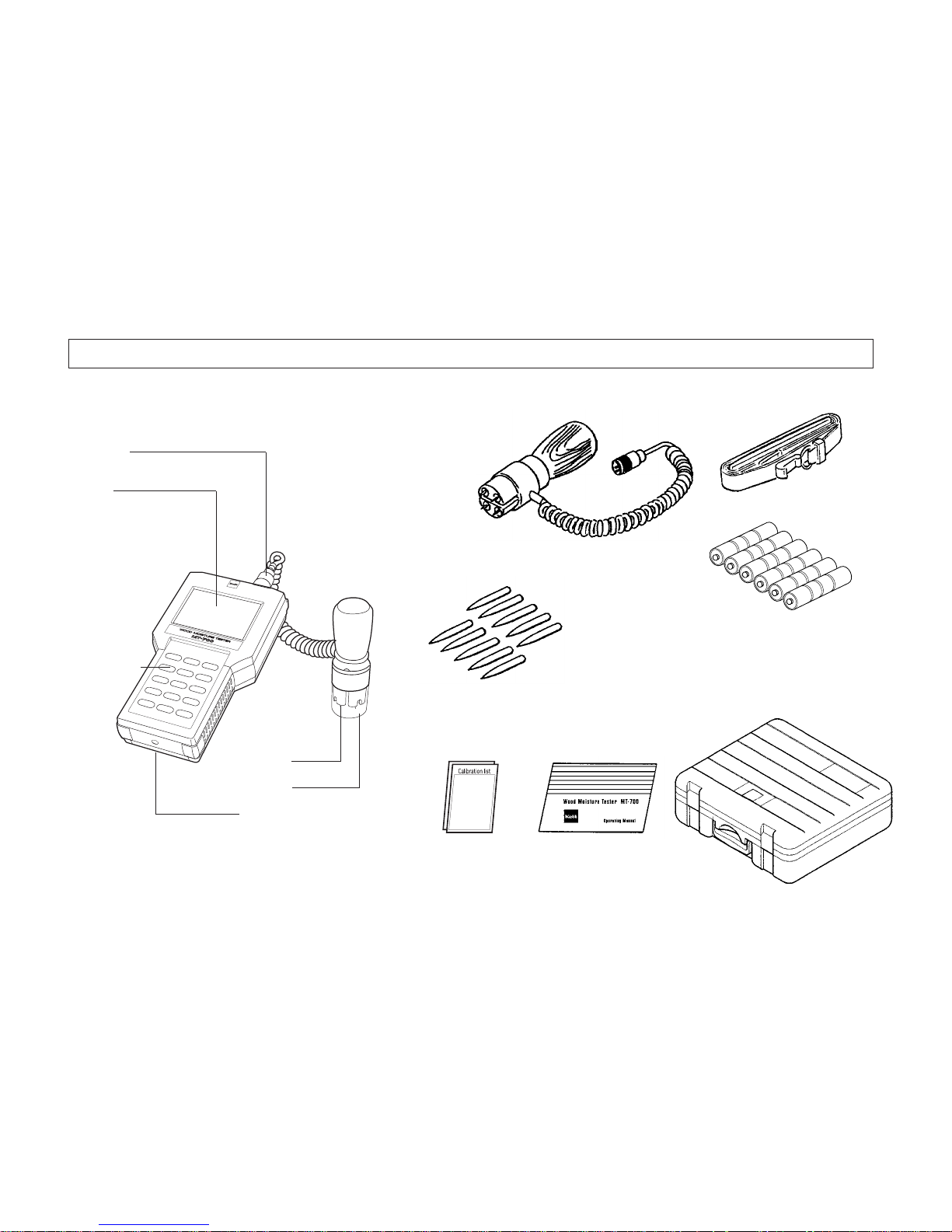
3. Part Names
Main body Accessories
Carryingcase
Shoulder strap
Calibration List (2)
Battery(6)
Operating Manual
Needle probe
Conductive rubber (2)Spare needle (10) Wrench
Connector
Display
Control Panel
Needle
Cap
Battery cover(Back)
Needle probe
Page 7
5
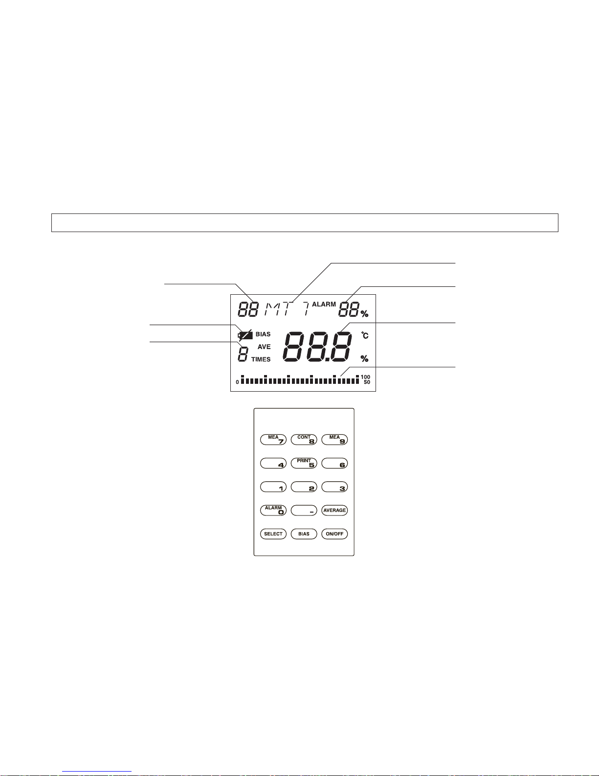
4. Displa y and Keypad
Wood group number
Battery indicator
Measuring times
"HRD" or "SFT"
Upper limit alarm
Moisture content
Bar graph
Display
Keypad
Page 8
6
5. Directions
5-1.Before Measuring
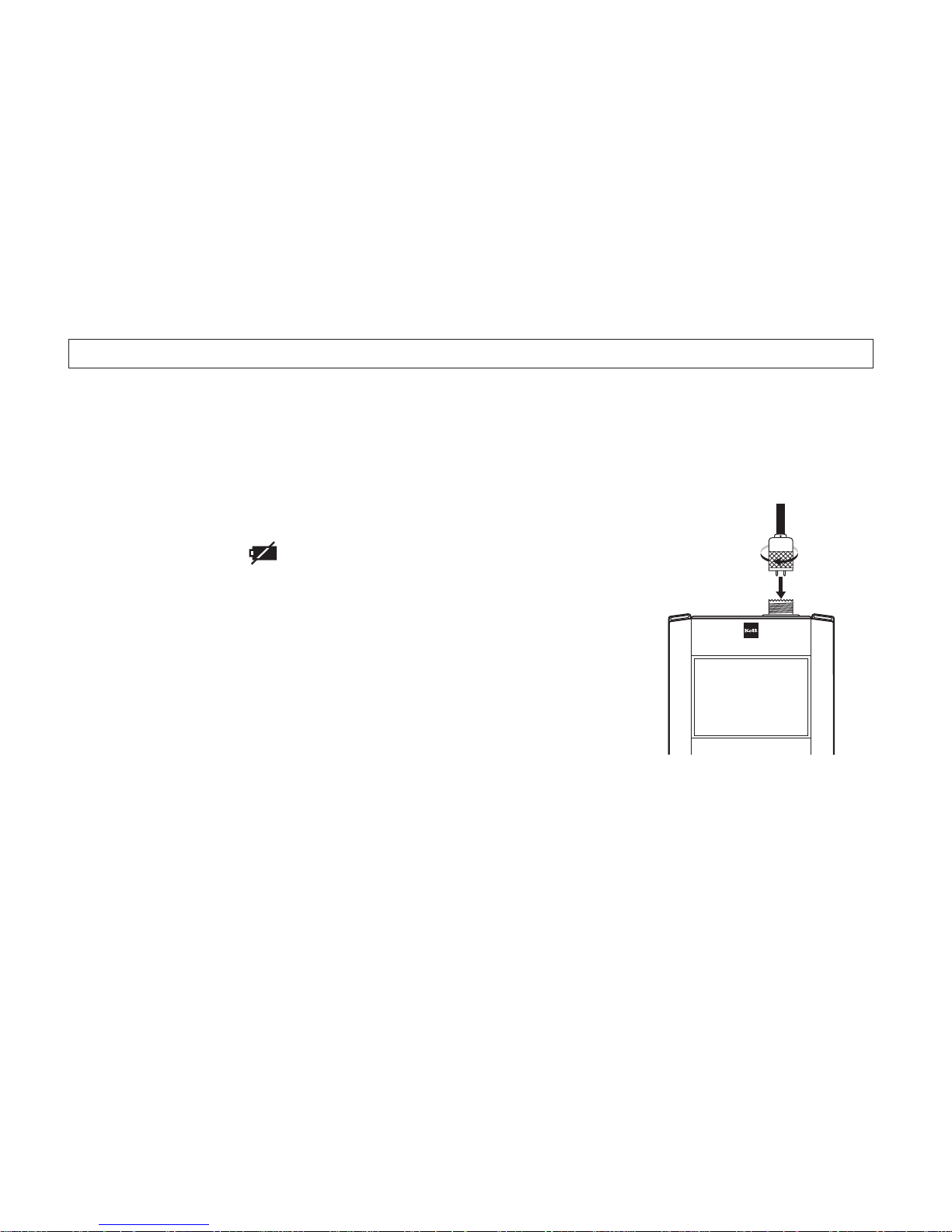
1.Load the batteries.
The unit is powered by six LR6 batteries.
Place the batteries in the compartment, taking care to correctly
orient the positive and negative terminls.
• The battery indicator is displayed when the batteries are exhausted.
Replace all six with new batteries.
2.Plug the probe connector into the probe socket on the top of the
unit.
3.Remove the protective cover of the probe.
4.Prepare the sample to be measured before measurement.
Allow it to equilibrate to the ambient temperature of the unit.
Page 9
7
5-2.Measurement Method
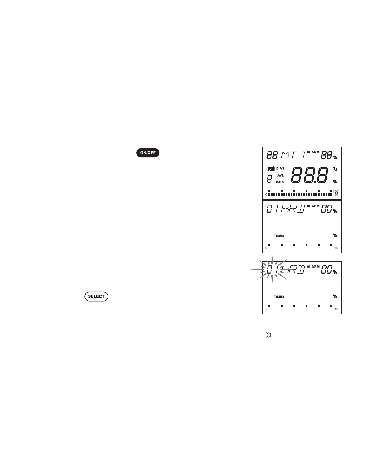
1.Turn on the MT-700. Press the key. All indicators will be
displayed for approximately three seconds.
The wood group number, "HRD" or "SFT" ,"TIMES" ,"%" will be
displayed.
• If this does not happen (as shown in Figure), a problem may exist with
the unit. Please see the error list (Section 6.Error Code Display).
2.Select the wood group from the Calibration List.
Wood group number is from 01 to 09 and from 10 to16.
Exaple : Wood group number 01 to 12
(1) Press the key. Be sure that wood group number is
blinking.
• The part of the display printed in indicates that this part is blinking.
Page 10
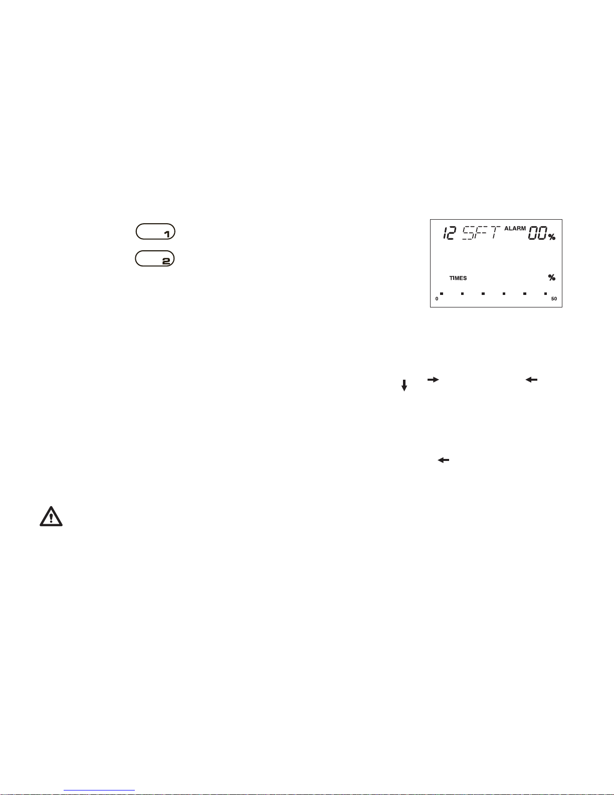
(2) Press the key. Single-digit is blinking.
(3) Press the key. "12", "SFT" will be displayed.
• The wood g roup n umber is maintained in memory when the unit's
power is off.
3.Press the probe into the wood to be measured as shown figure.
Place the probe on the wood in the same direction as figure shows,
so that electric current may penetrate at a right angle with the
flow of wood grain. Grasp the grip of the needle probe and insert
the needle up to 7mm into the wood to obtain the intemal moisture content of wood.
• Turn the red mark attached to the metal par t of the sensor in the
direction of grain.
• The tip of a sensor needle is a sharp shape. It may cause injury of
the operator or damage the other people by careless handling,
therefore it should be always capped after use.
8
Electric current
Grain direction
Code
Red mark
Page 11
9
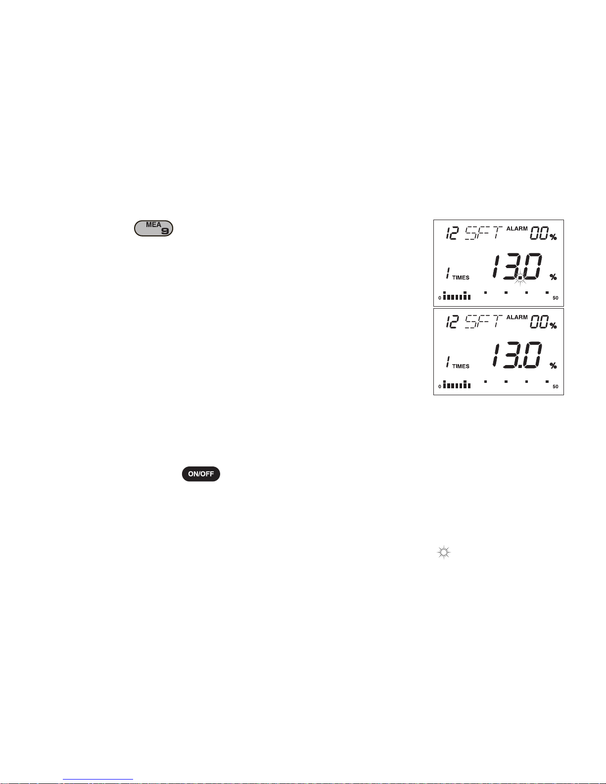
4.Press the key. The decimal point blinks.The moisture
content is displayed.
• Bar graph is displayed at the same time. (Full scale is 50%,every at
intervals of 2%.)
• When the moisture content is less than the lower limit of the measuring
range, LCD displayes "LO". When the moisture content is greater than
upper limit of the measuring range, LCD displayes "HI".
5.Remove the probe from the wood.
The moisture content is displayed at this time . If you wish to continue with further measurements,resume the procedure from
step3.(Press the probe into the wood to ...)
When ending, press key cut a power supply.
• When inactive, the unit will automatically power off after approximately
five minutes.
• The part of the display printed in indicates that this part is blinking.
Page 12
10
5-3.Displaying the average value
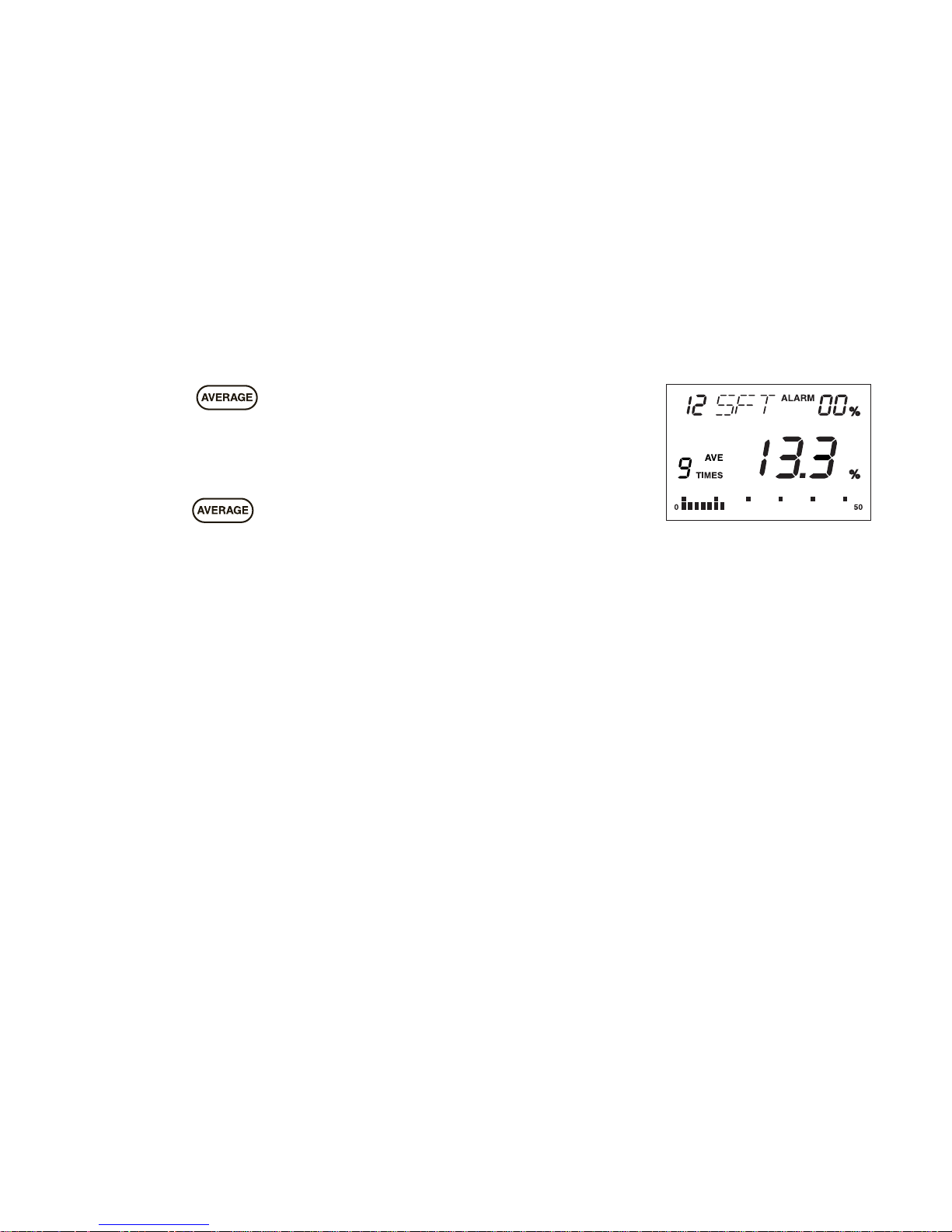
Press the key to display the average of the measured
values.
When the number of measurements is between 2 and 9, "AVE",
the number measurement and the average are displayed.
Once the key is pressed the number of measurements
resets to "1".
Page 13
5-4.Continuous Measurement
The unit automatically measures in the continuous measurement mode.
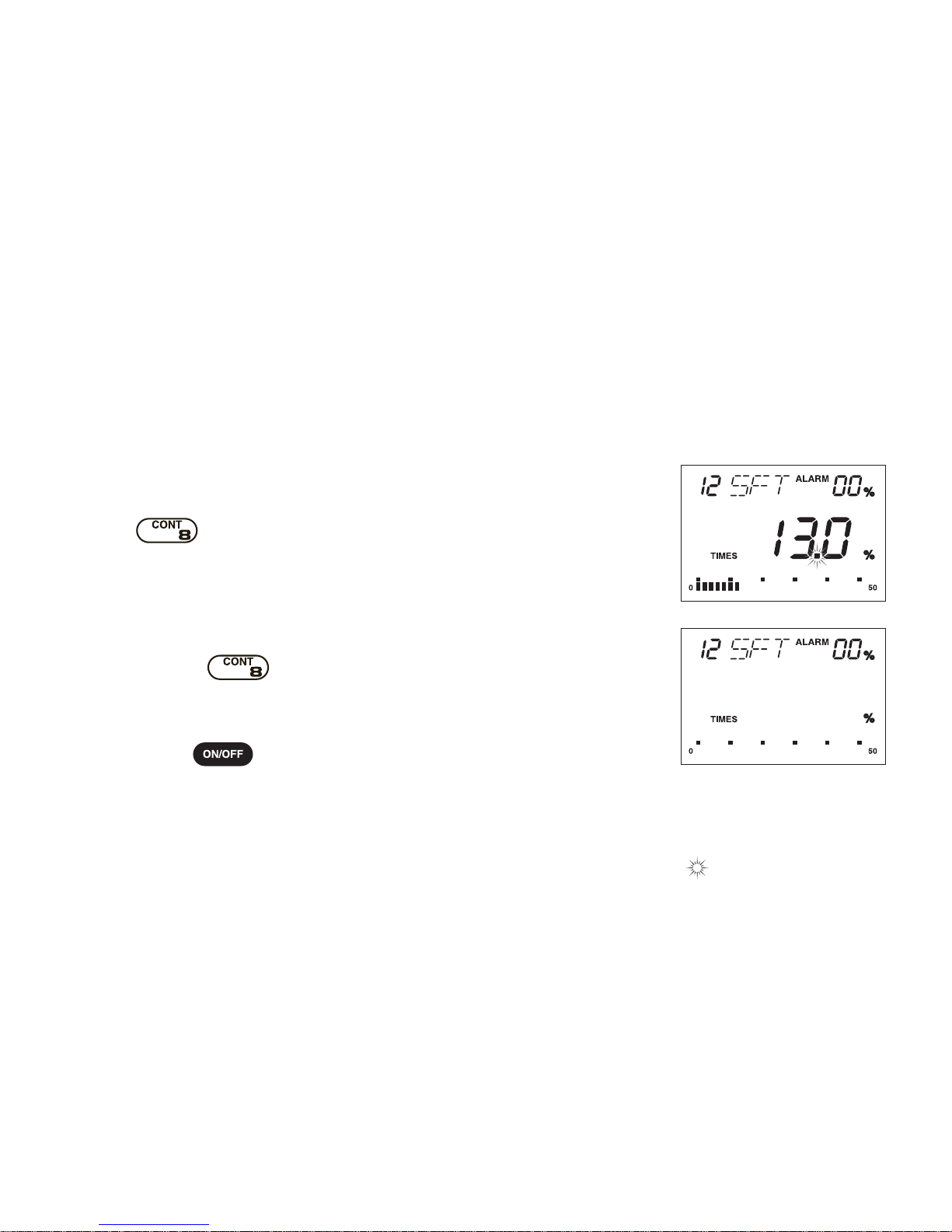
1.Changing to the continuous measurement mode.
In step "5-2.Measurement Methhod 4.Press the ...", press the
key. The decimal point blinks and the moisture content
is displayed. "LO" is displayed when the probe is not inserted
into wood or the moisture content is below the measuring range.
2.Resetting the continuous mode.
Press the key continuously f or 1-2 seconds. The buzzer
sounds. The unit resets to the normal mesurement mode.
• Press the key. The unit resets to the normal measurement mode.
• Battery life is shorter in this mode than the normal measurement mode.
(Battery life is about 24hours at 20˚C in the continuous measurement mode.)
11
• The part of the display printed in indicates that this part is blinking.
Page 14
12
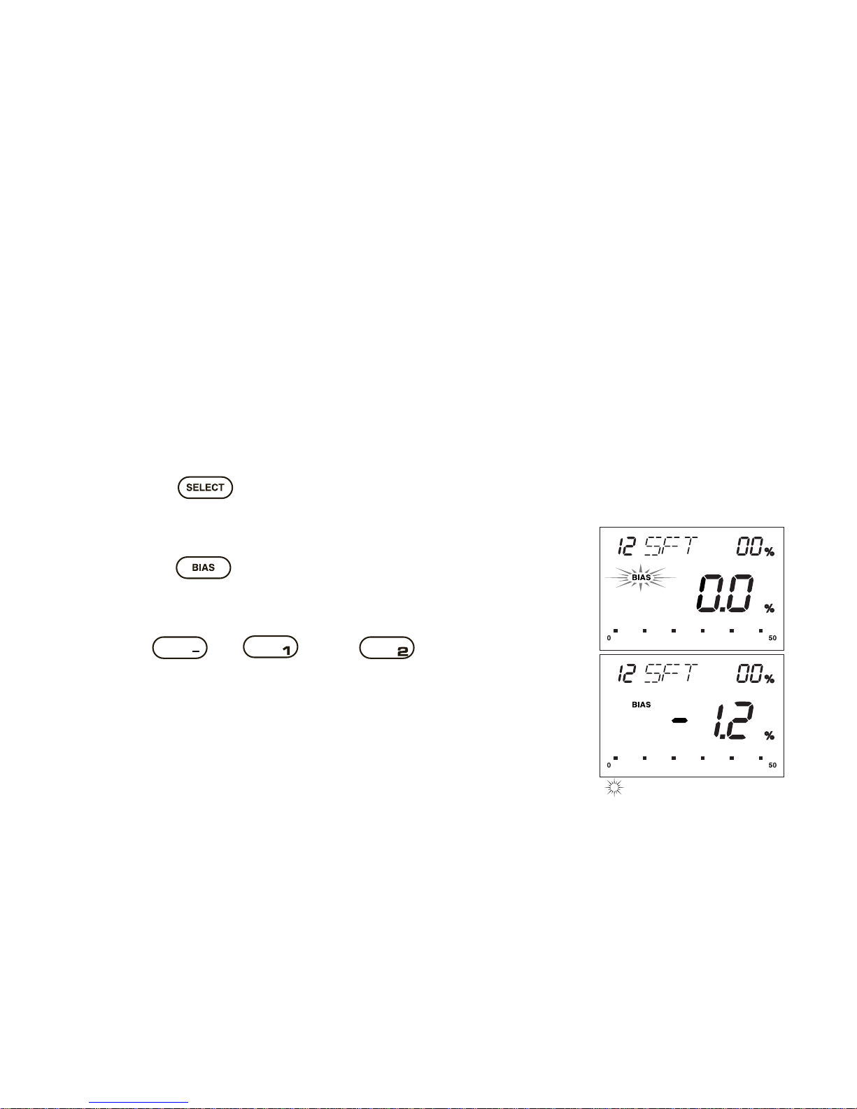
5-5.Performing Moisture Content Bias Adjustment
A moisture content bias adjustment can be made from -9.9% to +9.9% for each wood group. Input a bias
value if the moisture content has a discrepancy against the official standard.
Example : Wood group number 12. The bias value should be decreased by 1.2.
1.Slect the wood group.
Press the key. Press the number keys for the proper
wood group. (Refer to "2.Select the wood group" on page 7.)
2.Set the unit to the bias adjustment mode.
Press the key. The "BIAS" indicator blinks and the bias
value is displayed. The bias value is initially set to "0.0".
3.Input the bias.
Press key, key and key.
4.If you wish to continue with further measurements, resume the
procedure from step "5-2.Measurement Methhod 3.Press the
probe into the wood to...".
5.The "BIAS" indicator is diplayed if the bias value is not 0.0.
6.The bias value is maintained in memory even when the unit's
power is off.
• The part of the display printed in indicates that this part is blinking.
Page 15
13
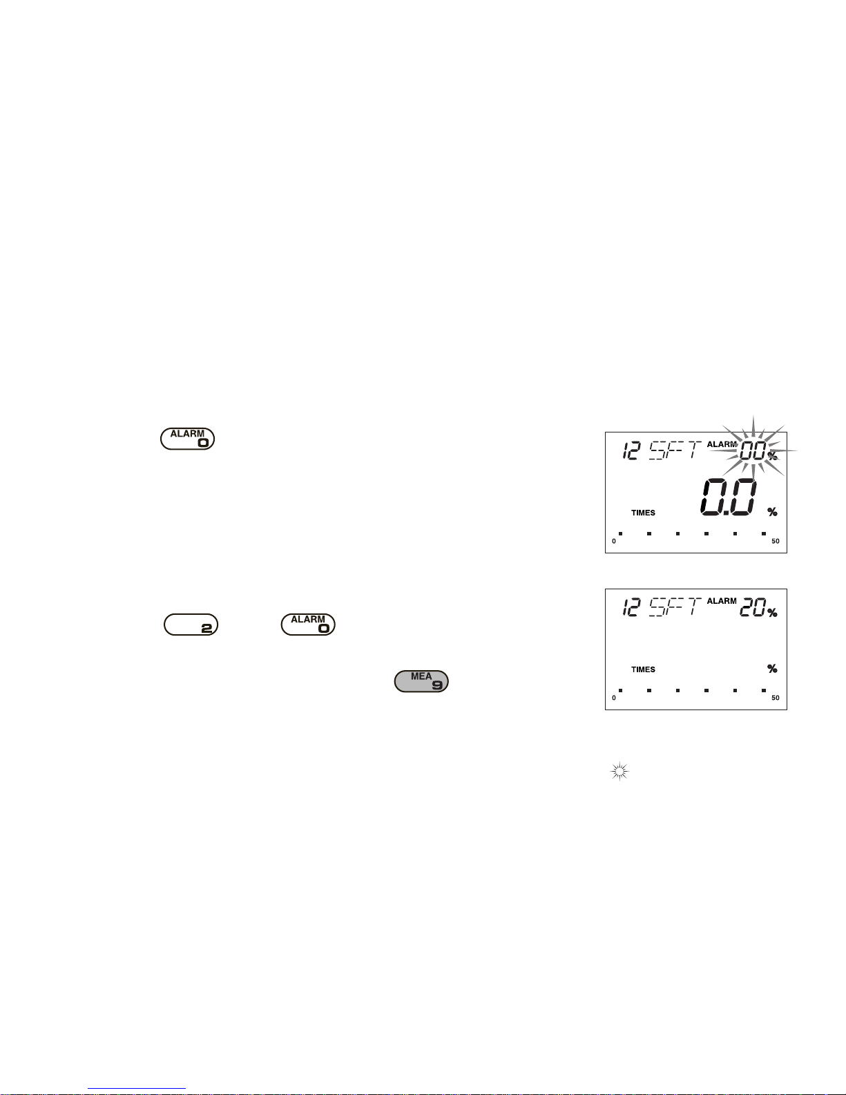
5-6.How to set an alarm value
The unit has alert function. Buzzer sounds, when the moisture content to be measured exceeds the alarm
value.
1.Press key.
The two digits figures will blink on the right side of "ALARM".
2.Input the alarm value.
Example : 20%
Press key and key. The alar m value will be
displayed.
3.Measurement will be done by pressing the key.
• The part of the display printed in indicates that this part is blinking.
Page 16

14
6. Error Code Displa y
An eror code will be displayed whenever an error occurs.
The error code will be diplayed for 4 seconds,then the power turns off.
1.There is a problem with the temperature sensor. Repair is necessary.
2.There is a problem with the electronic circuit used for moisture
measurement. Repair is necessary.
Page 17

15
3.The measurement cannot be made because the temperature of
the unit is below 5˚C.
Raise the temperature of the unit before making mesurements.
4.The measurement cannot be made because the temperature of
the unit is above 50˚C.
Lower the temperature of the unit before making mesurements.
Page 18

16
7. Applications and Ranges
Number HRD/SFT Name of wood Measuering Range
01 HRD Zelkova 6~40%
02 HRD Oak,Cherry,Chestnut 6~40%
03 HRD Birch 6~40%
04 HRD Apitong 6~40%
05 HRD Ramin,Kempas 7~30%
06 HRD Ash 5~40%
07 HRD Teak 6~40%
08 HRD Lauan,Meranti 6~40%
09 SFT Larch 6~40%
10 SFT Cotton wood 6~40%
11 SFT Hemlock 7~40%
12 SFT Spruce 7~40%
13 SFT Cypress 7~40%
14 SFT Pine 8~35%
15 SFT Cedar 7~35%
16 SFT Fir 6~40%
Page 19

Page 20

0505・TO・0402・100
 Loading...