

Page 1
Infrared Moisture Determination Balance
FD-720
Operating Manual
Page 2

Page 3
Infrared Moisture Determination Balance Safety NotesFPL950701
Improper use of the infrared moisture tester in violation of the following safety notes may result in death, injury or damage to
property due to fire, etc. Furthermore, the infrared moisture tester has high temperature components which can cause burns
if proper safety guidelines are not followed.
Observe all safety guidelines
Carefully read and observe all safety notes included in this user’s manual.
Do not use the unit if it appears to be malfunctioning
If you suspect a problem or malfunction in the unit, discontinue use and immediately have the unit inspected by certified
Kett service personnel.
Meanings of Warning Indicators and Symbols
The following symbols are used in this operating manual and product to prevent accidents from occurring as a result of
improper usage or handling. The meaning of each symbol is as described below.
Failure to observe these items may lead to death or injury to the user.
Failure to observe these items may lead to injury to the user or damage to property.
Items which the user should be aware of in order to use the unit safely.
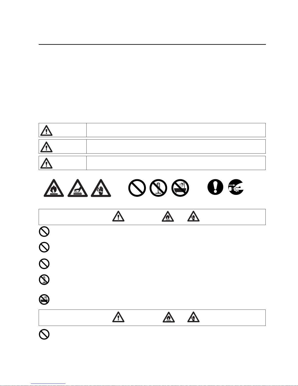
Caution Symbols Stop Symbols Symbols Requiring User Action
Fire Hazard Burn Hazard Electric Shock Prohibited Do Not Do not Expose Required Disconnect Plug
Hazard Disassemble to Water Action from Electrical Outlet
Do not attempt to measure samples which may undergo dangerous chemical reactions when heated, as doing so
may result in an explosion or release of toxic gas.
Do not place flammable materials near the infrared moisture tester.
Some parts of the infrared moisture tester become extremely hot during operation and could lead to a fire if
flammable materials are placed nearby.
Never use with any power source for which the product was not designed.
Application of excessively high voltage may result in overheating, malfunction, or fire.
Do not attempt to disassemble, modify or rebuild the infrared moisture tester.
Doing so may result in accident, electric shock, etc. If you believe the unit may be malfunctioning, take it to an
authorized Kett service center for service.
Do not allow the unit to come in contact with water.
The infrared moisture tester is not waterproof. Do not allow water or other liquids to get into the unit’s enclosure as
this may lead to electric shock or malfunction.
Do not touch the heat-dispersing component of the heater cover or sample dish with your bare hands, as doing
so might result in burns.
This infrared moisture tester is at high temperature during and immediately after making measurements. When
touching the unit, only use the specified control knobs and accessories.
Warning
Caution
Note
Warning
Fire Hazard Electric Shock Hazard
Caution
Burn Hazard Electric Shock Hazard
Page 4

Contents
1. Precautions to be observed when taking measurements .................... 6
2.
Description of Features and Principles of Operation .................................
8
2-1 Principles of Operation............................................................................................. 8
2-2 Features ................................................................................................................... 8
2-3 Applications (i.e., materials which can be measured) ............................................. 8
3. Specifications ........................................................................................... 9
4. Names of Individual Parts and Components ......................................... 10
4-1 Names of Parts of Main Unit .................................................................................... 10
4-2 Parts and Accessories ............................................................................................. 11
5. Display and Control Panel ....................................................................... 12
5-1 Display......................................................................................................................12
5-2 Control Panel Operations......................................................................................... 13
6. Assembly and Installation of Main Unit.................................................. 14
7. Tips on how to ensure accurate measurements ................................... 17
8. How to Conduct Measurements.............................................................. 19
9. Specifying Measuring Conditions........................................................... 23
9-1 Types of Settings...................................................................................................... 23
9-2 Descriptions of Individual Measuring Condition Settings ........................................ 23
9-2-1 Selecting the CONDITIONS (Measuring conditions storage area) ............. 24
9-2-2 Selecting the MODE (Measuring mode)...................................................... 25
9-2-3 TEMP (Drying temperature)......................................................................... 34
9-2-4 Bias .............................................................................................................. 35
10. Menu Settings ........................................................................................... 36
10-1 Types of Menu Settings............................................................................................ 36
10-2 Descriptions of Individual Menu Items ..................................................................... 36
10-2-1 Selecting units (measurement standard and minimum display units)......... 37
10-2-2 Specifying the type and format of output..................................................... 38
10-2-3 Specifying sample codes ............................................................................. 41
10-2-4 Setting the date and time............................................................................. 42
10-2-5 CAL (Scale calibration) ................................................................................ 43
10-2-6 Specifying a device ID ................................................................................. 45
10-2-7 Specifying a password ................................................................................. 46
10-2-8 Specifying the power settings ...................................................................... 47
Page 5

11. Error Messages......................................................................................... 48
12. Predictive Measurements ........................................................................ 50
12-1 A Description of Predictive Measuring..................................................................... 50
12-2 Procedure for Obtaining Predicted Measurements.................................................. 52
12-2-1 Calculating the bias to be specified when operating in predictive
measurement mode ..................................................................................... 52
12-2-2 Evaluating predicted measurements ........................................................... 54
12-2-3 Obtaining predicted measurements............................................................. 55
13. Printing Output to a Printer (Option) ...................................................... 56
13-1 Sample Printer Output ............................................................................................. 56
13-2 Outputting Past Measurement Data......................................................................... 59
14. Computer Interface................................................................................... 60
14-1 RS-232C Interface Specifications............................................................................ 60
14-2 Setting Up and Transmitting Data ............................................................................ 61
14-2-1 Connecting the RS-232C cable ................................................................... 61
14-2-2 FD-720 settings............................................................................................ 61
14-2-3 Starting up the computer ............................................................................. 61
14-3 Computer Output Format ......................................................................................... 62
15. Maintenance.............................................................................................. 64
15-1 Performing Maintenance .......................................................................................... 64
15-2 Replacing Fuses ...................................................................................................... 65
Page 6
6
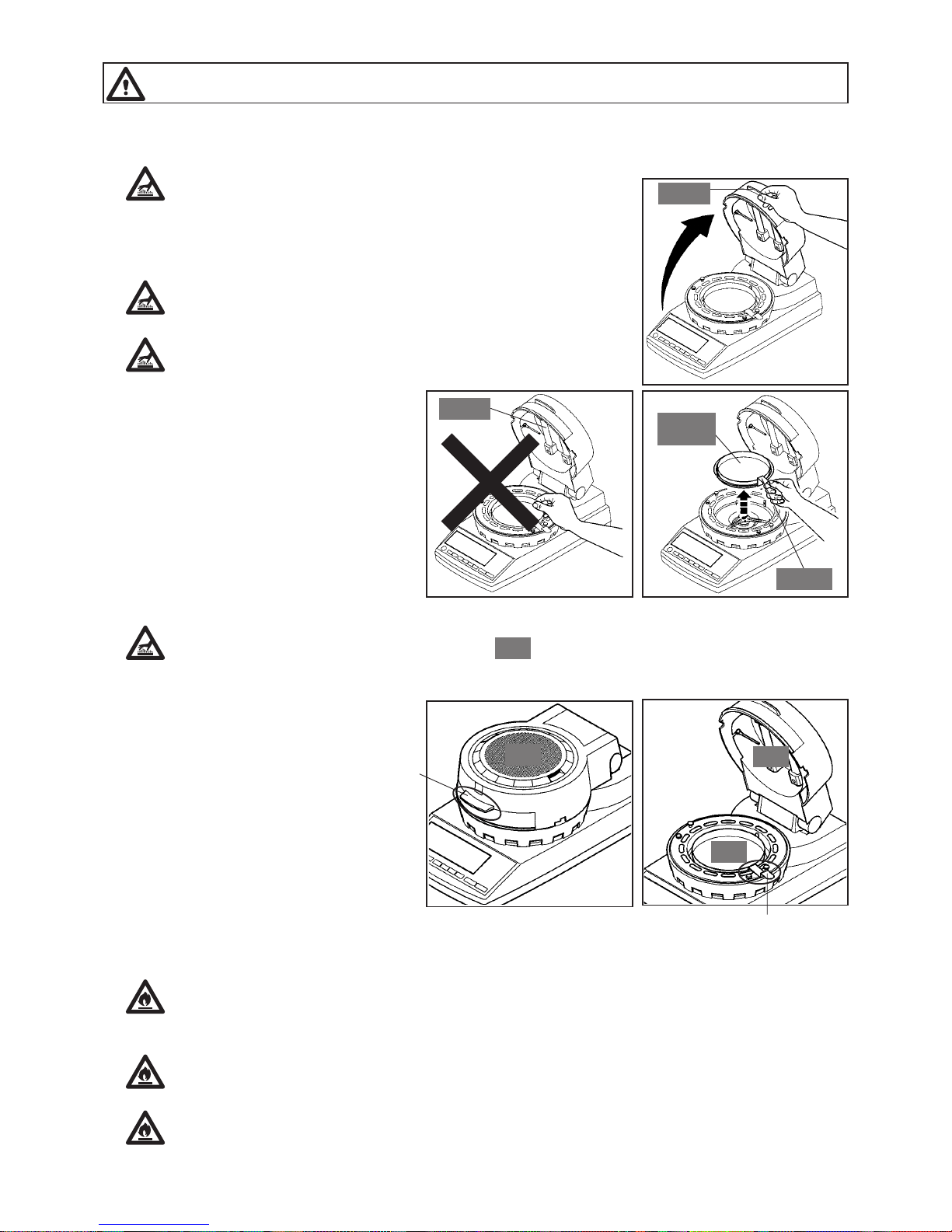
Be sure to follow proper procedures during operation
When opening or closing the lid to the heater, always be sure to use the
handle.
Be sure to put the wind shield, sample dish tray, handler, and sample
dishes properly into place. (See “6. Assembly and Installation of Main
Unit” on p. 14 for instructions.)
Always be sure to use the provided handler to remove sample dishes.
When removing a sample dish, do not allow your hands to come into
contact with the heater or any of the metal (aluminum) parts around the
heater, as doing so could result in burns.
The sample dish and area around the sample dish will be very hot
immediately after performing a measurement. Be sure to place the
sample dish in an appropriate place to allow it to cool.
Areas to touch and areas subject to high temperatures
1. Precautions to be observed when taking measurements
Handle for holding heater lid
Place to grasp handler
Heater
Never perform measurements using hazardous materials
Heating materials which would present a risk of explosion or combustion, or materials which could give
off noxious fumes when heated, is extremely dangerous and this instrument should never be used with
any such materials. The same also applies to the use of any materials which might cause hazardous
chemical reactions to take place when heated.
When heating materials that would first dry along the surface, and then allow the internal pressure to rise
excessively, there is a danger that heating such materials could cause them to rupture. Such materials
should never be measured, as doing so could be dangerous.
If any materials being measured ignite, immediately remove the power plug from its socket and take
appropriate measures extinguish the fire.
While a measurement is being performed or immediately after a measurement has been performed, the
areas marked in the accompanying diagrams as will heat up to high temperatures. When handling
the unit, always be sure to allow your hands to come into contact only with the designated areas.
Handle
Sample
dish
Handler
HOT
HOT
HOT
HOT
Page 7
7
Never place any easily flammable objects near the product
The components of the infrared moisture tester can become very hot when measurements are
being taken or immediately after measurements have been taken. The heat could cause
objects or materials to catch fire if they were to come into contact with the unit, an d no easily
flammable objects or materials should be kept near the product.
Never place any objects which might easily be damaged by heat near the unit, as doing so
might result in deformation or damage to the objects in question.
No objects should ever be placed upon the heater.
If you see fire coming from the unit or notice smoke, an odd smell, or any other sign of abnor-
mal functioning, remove the power plug from its socket, or take whatever other steps would be
appropriate to deal with the problem.
Notes on using the control keys
Never turn on the power to the unit while holding down any of the control keys.
Never press any keys other than those directed or press two or more keys together at the same
time unless directed to do so.
When there is any danger that the unit might be damaged by lightning, remove the power plug
from its socket.
Stopping operation
The key can be pressed at any time during operation to halt operation. If you suspect
for any reason that the product is not operating properly or that there is any sort of danger,
immediately press the key to halt operation.
Setup and storage
Avoid using or storing the unit in a location where it would be exposed to excessively high or
low temperatures, high levels of humidity, direct sunlight, electromagnetic interference, corrosive gases, or large amounts of dust.
Place the unit on a flat and stable surface where it will not be subjected to significant vibration
during use.
When moving the unit, never tilt it any more than necessary.
Take care never to drop or bump the unit or otherwise allow it to be subjected to strong shocks
or the application of excessive force.
When removing the power cord or RS-232C interface cable, never pull on the cord or cable and
instead hold the plug or cable connector when removing.
When the unit is not to be used over an extended period of time, remove the power plug from
its socket.
Page 8

8
2. Description of Features and Principles of Operation
2-1 Principles of Operation
This unit determines the moisture and solid contents of samples by heating them using infrared
illumination and measuring changes in mass due to evaporation. This is referred to as the loss on
drying method and is the simplest method for determining moisture content and thus mandated by
many public regulations related to measurement standards.
2-2 Features
UniBloc sensor
The core of the scale is formed by a single-unit aluminum UniBloc*1 weight sensor which provides excellent responsiveness, temperature characteristics, and shock resistance. This UniBloc*
1
sensor ensures excellent reliability in moisture
content measurements even over extended use.
New Auto Taring mechanism
The FD-720 comes with an internal Auto Taring mechanism which makes it possible to perform reset correction while
performing measurements, thus eliminating drift of the scale even when performing measurements over long periods of
time and making it possible to obtain extremely reliable measurements.
Mid-infrared quartz heating lamp
The FD-720 uses a mid-infrared quartz heating lamp (with a central wavelength of 2.6 µm). This heater provides
excellent drying efficiency over a wide range of different types of sample, makes it difficult for differences to occur as a
result of the colors of different samples, and eliminates the overheating of sample surfaces, thus making it possible to
obtain ideal drying conditions.
What‘s more, this heating lamp also provides a long service life 5~10 times greater (20,000 to 30,000 hours*
2
) than
older infrared or halogen lamps.
A wide selection of measuring modes
The FD-720 provides a wide selection of measuring modes (automatic halting mode, timed halting mode, high-speed
drying mode, low-speed drying mode, stepped drying mode, and predictive measuring mode) which makes it possible to
perform measurements under the drying conditions most appropriate to the drying characteristics of the sample being
measured.
The ability to store measuring conditions
The FD-720 provides 10 measuring conditions storage areas which may be used to store sets of measuring conditions
to be used for different types of materials, thus reducing the amount of time involved in specifying settings before
performing measurements.
Data memory
The FD-720 is able to store up to 100 sets of measurement data in memory, thus making it possible to output large
batches of data all at one time.
Printer port
The FD-720 is equipped with a printer port which may be used to connect to a (separately sold) printer, thus making it
possible to print out text or graph data showing final measurements, or intermediate drying states while performing
measurements.
Scale calibration
The scale of the FD-720 can be calibrated, and it is possible to print output during calibration meeting GLP, GMP, or ISO
standards.
The ability to display changes in moisture content (∆M) in a numeric and scalar display
The change (∆M) in moisture content over 30-second intervals is displayed in a numeric and scalar display, thus making
it easier to estimate when a measurements should be completed. This feature is also useful in helping to determine
measurement completion conditions.
*1 UniBlock is a product name of the Shimadzu Corporation.
*2 Indicates actual measured time for operation of infrared heater. Your performance may vary.
2-3 Applications (i.e., materials which can be measured)
Materials for which water is the only main component which evaporates as a result of heating
Materials for which no dangerous chemical reactions or other changes occur as a result of
heating
* Measurements can be performed using virtually any material meeting these conditions.
Page 9

9
3. Specifications
Measurement format : Evaporation weight loss method (Heat drying and weight loss method)
Sample weight : 0.5~120 g using selective weight sampling method
Minimum displayable units
: Moisture content (solids): 0.1% or 0.01% (selectable), Weight: 0.001 g
Measurable quantities : Moisture content (wet base & dry base), weight, solid content
Measurement range: : 0-100% (wet base, solids)
0-500% (dry base)
Reproducibility (Standard deviation)*
1
: Samples with a weight of 5 g or higher: 0.05%
Samples with a weight of 10 g or higher: 0.02%
*1When using standard samples and measuring conditions as determined
by Kett Electric Laboratory.
Measurement modes : Automatic halting mode
Timed halting mode (with measurement times of 1~240 minutes or
continuous measurement mode, with a maximum measurement time of
12 hours)
High-speed drying mode (may be used with either automatic or timed
halting mode)
Low-speed drying mode (may be used with either automatic or timed
halting mode)
Stepped drying mode (performs drying in 5 steps)
Predictive (comparative) measuring mode
Temperature range : May be set within a range of 30~180°C in 1-degree increments
Display : Backlit LCD display (137 x 43 mm)
External output : RS-232C interface
Communications : Data may be output from the Data Logger software KDL-01 (sold
separately) or similar software.
Storage of measurement conditions
: Allows for storage of 10 sets of measurement conditions
Data memory : Allows for storage of 100 sets of data
Environmental conditions : Pollution degree 2, Altitude up to 2000 m
Temperature/humidity operating range
: 5~40°C, maximum of 85% RH
Heat source : Medium frequency infrared heater (200W x 2)
Temperature sensor : Thermistor
Power supply, Power consumption
: AC 100V~120V (50/60 Hz) 900W
AC 220V~240V (50/60 Hz) 900W
Weight and external dimensions
: 4.5 kg, 220 x 415 x 190 mm (W x D x H)
Sample dish : SUS sample dish (Diameter: 130 mm; Depth 13 mm)
Items included : 2 sample dishes, 2 sample dish handlers, wind shield, sample dish tray,
spoon & spatula set, 2 spare (T8A 250V) fuses, 2 packages of aluminum
foil sheets (10 per package), operating manual
Optional equipment : Printer set (includes a VZ-330 printer, a printer interface cable (VZC-14),
printer paper, and an AC adapter), printer paper (10 rolls), package of
aluminum foil sheets (500 sheets), RS-232C cable (VZC-52),
Data Logger software KDL-01, TQ-100 sample crusher
Page 10
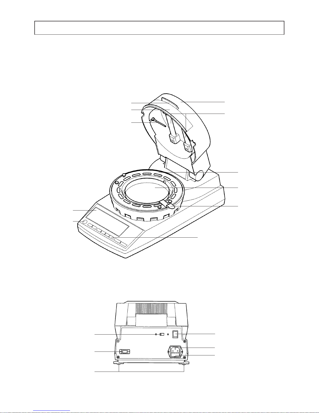
10
4. Names of Individual Parts and Components
4-1 Names of Parts of Main Unit
Handle
Observation window
Temperature sensor
Heater lid
Display
Level
Heater
Wind shield
Sample dish
Sample dish handler
Control panel
Power conversion switch
Power switch
Power inlet
Fuse holder
RS-232C port
Height adjustment legs
Page 11
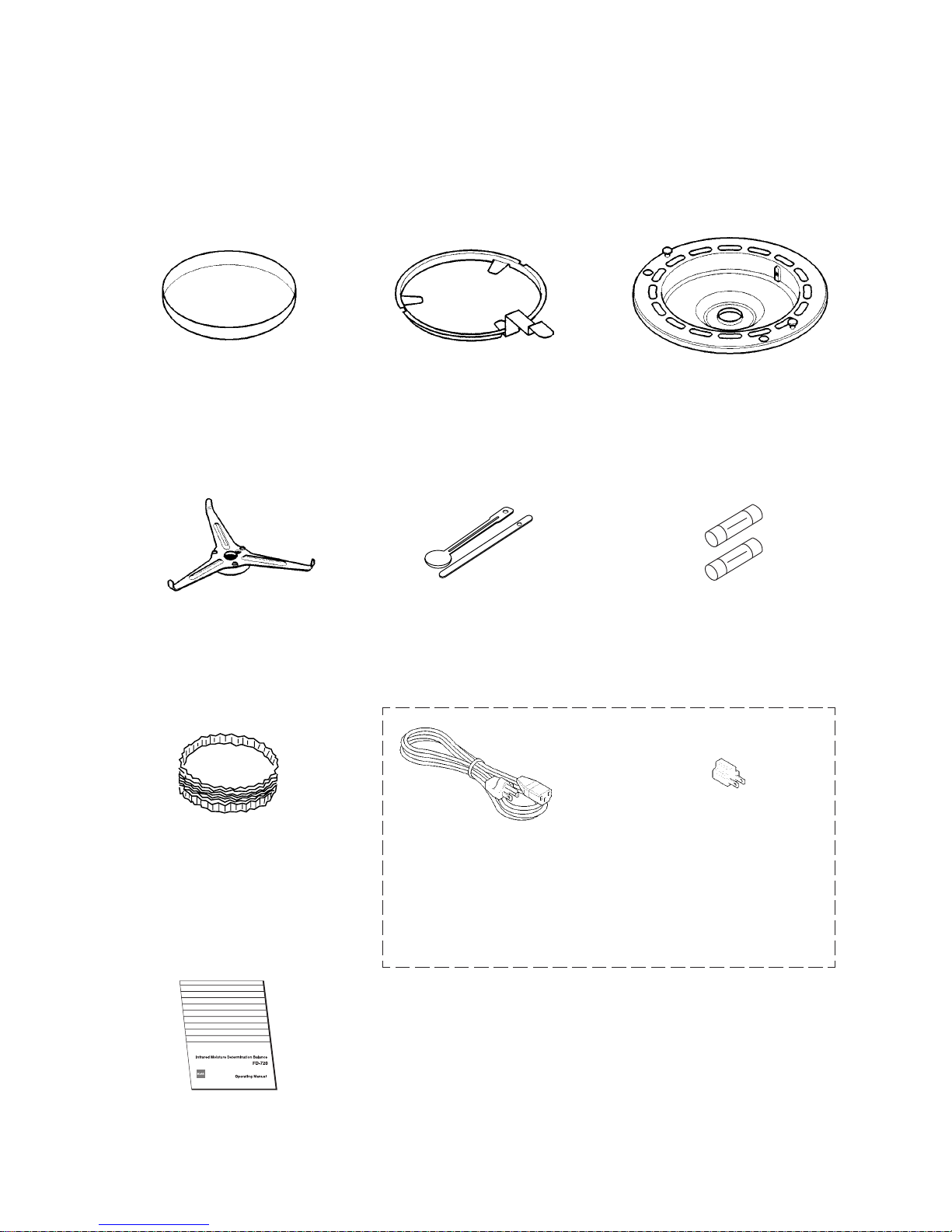
11
4-2 Parts and Accessories
Sample dishes (2) Sample dish handler (2) Wind shield
Sample dish tray Spoon & spatula set Spare (T8A 250V) fuses (2)
(Power cord) (Three-prong plug adapter)
Operating manual
Packages of
aluminum foil sheets
(10 per package) (2)
Note: The shape of the power plug var ies in different countries.
The actual accessory may be different from the one in this
illustration.
Page 12
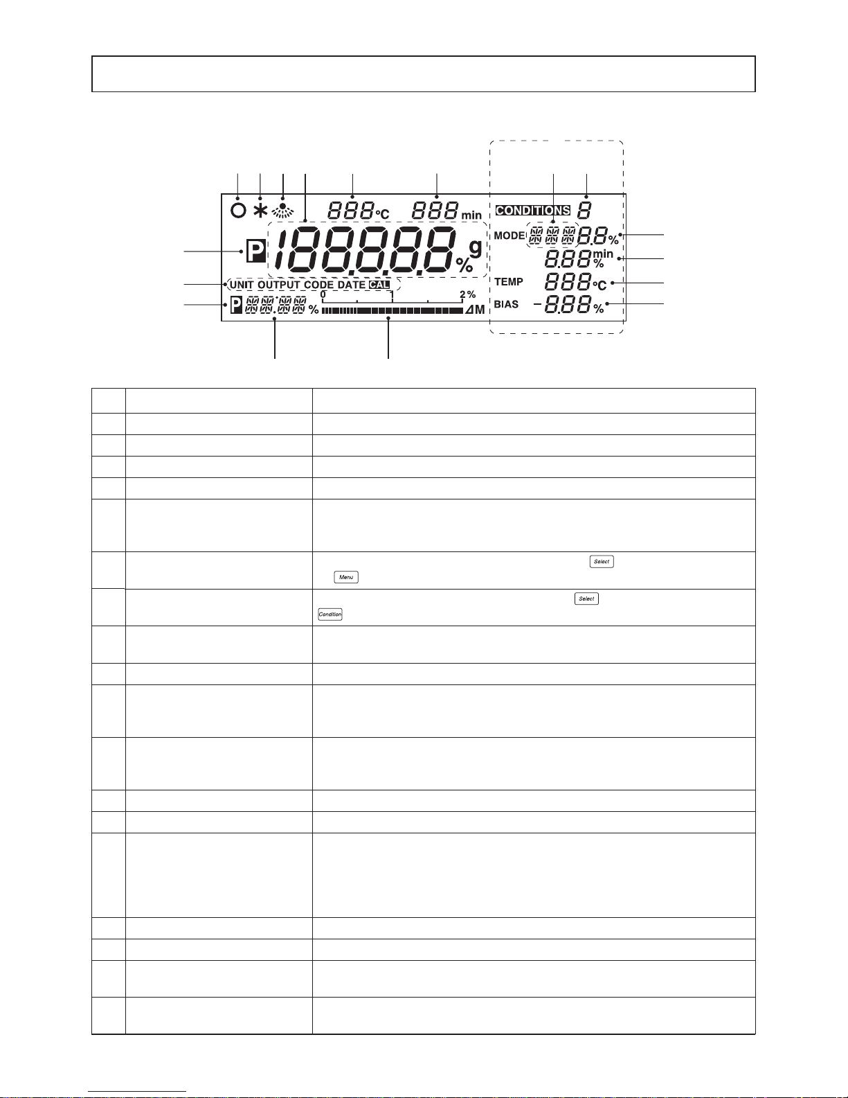
12
5. Display and Control Panel
5-1 Display
Item
1
2
3
4
5
6
7
8
9
0
!
@
#
$
%
^
&
*
Name
Stability indicator
Measuring complete indicator
Heater on indicator
Predictive measuring indicator
Predictive measuring indicator (Lights
when performing comparative
measurement)
Menu display
Measuring conditions display
Measuring conditions storage area
display*
Measuring mode display*
Predictive measurement convergence
conditions display*
Halt conditions display*
Drying temperature display*
Bias display*
Moisture/Solid/Weight display
Temperature display
Measuring time display
Change in moisture (solid) content
display
Change in moisture (solid) content
scale display
Description
This indicator lights up when the internal scale is stable.
This indicator lights up when measuring has been completed.
This indicator flashes whenever the heater is turned on.
This indicator lights up when performing predictive measurements.
This indicator lights up when measuring has been completed after performing a comparative predictive
measurement.
Used to display individual menu items in sequence each time the key is pressed after pressing
the key.
Flashes to display individual items in sequence each time the
key is pressed after pressing the
key. Values may be specified for a given item when it is flashing.
Used to display the number of the currently selected measuring conditions storage area.
Used to display the currently selected measuring mode.
Used to display the conditions for convergence of measured values when operating in predictive or
comparative mode. When operating in high-speed drying mode, used to display the conditions required
in order to maintain a high-speed drying temperature.
Used to display the currently selected halt conditions. When the value is displayed as a percentage, it
indicates that measuring will halt automatically, and when value is displayed in minutes, it indicates that
measuring will halt when the specified amount of time is reached.
Used to display the currently selected drying temperature.
Used to display the moisture (or solid) bias.
When measuring weight (i.e., when in idling mode), used to display the weight in grams. When
performing measurements, used to display the moisture content and solids content as percentages.
When measuring weight, this display is also used to display ‘oL’ (i.e., overload) when the weight
exceeds the maximum measurable weight and to display ‘–oL’ (i.e., no overload) when the weight does
not exceed the maximum measurable weight.
Used to display the temperature under the heater lid.
Used to display the amount of elapsed time during measuring.
Used to display the change (∆M) in moisture (or solid) content at 30-second intervals during
measurement.
Used to display the change (∆M) in moisture (or solid) content in scalar format. The scale may display a
maximum change of 2 percent/30 seconds.
* Items marked with an asterisk display as flashing items.
Display as it appears with the power on.
(All display items shown.)
12 3$ % ^ 9 8
&*
0
!
@
#
7
4
6
5
Page 13
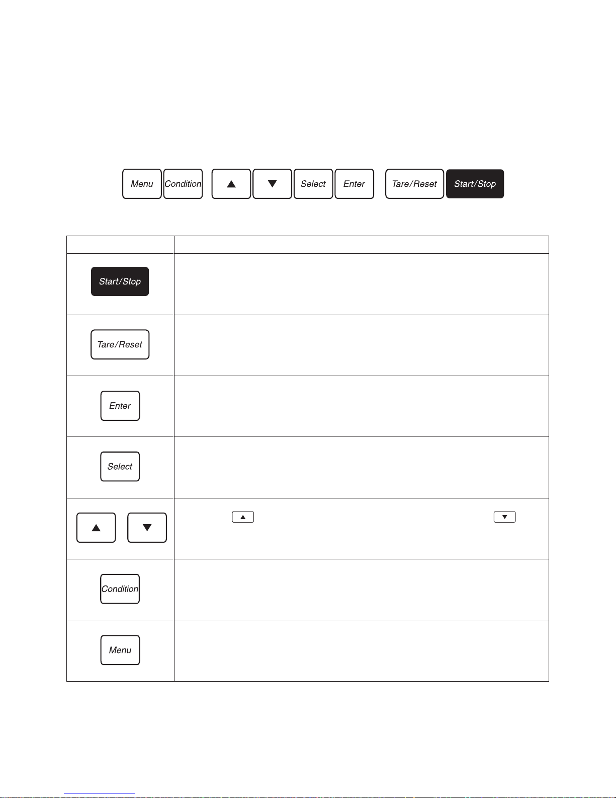
13
5-2 Control Panel Operations
The control panel keys are used to perform the following operations.
Name
START/STOP key
TARE/RESET key
ENTER key
SELECT key
UP key / DOWN key
CONDITION key
MENU key
Operation
Used to start measuring or to abort a measuring operation.
Also used to turn off the alarm which sounds to indicate that a measuring operation has been
completed.
Used to deduct the tare weight.
Also used to perform a reset after an error has occurred.
Also used to return to display of weight after completion of measurement.
Used to confirm currently selected settings.
When further settings must be specified, pressing the ENTER key causes the next specified
item to be displayed; when there are no further settings to be selected, the specified setting is
confirmed and takes effect.
Used to select different settings or setting values.
Used to change the value of different settings.
Pressing the
key causes the value in question to increase, and pressing the key
causes the value in question to decrease.
Used to begin or end the specification of measuring conditions.
Used to begin or end the specification of menu settings.
Page 14
14
6. Assembly and Installation of Main Unit
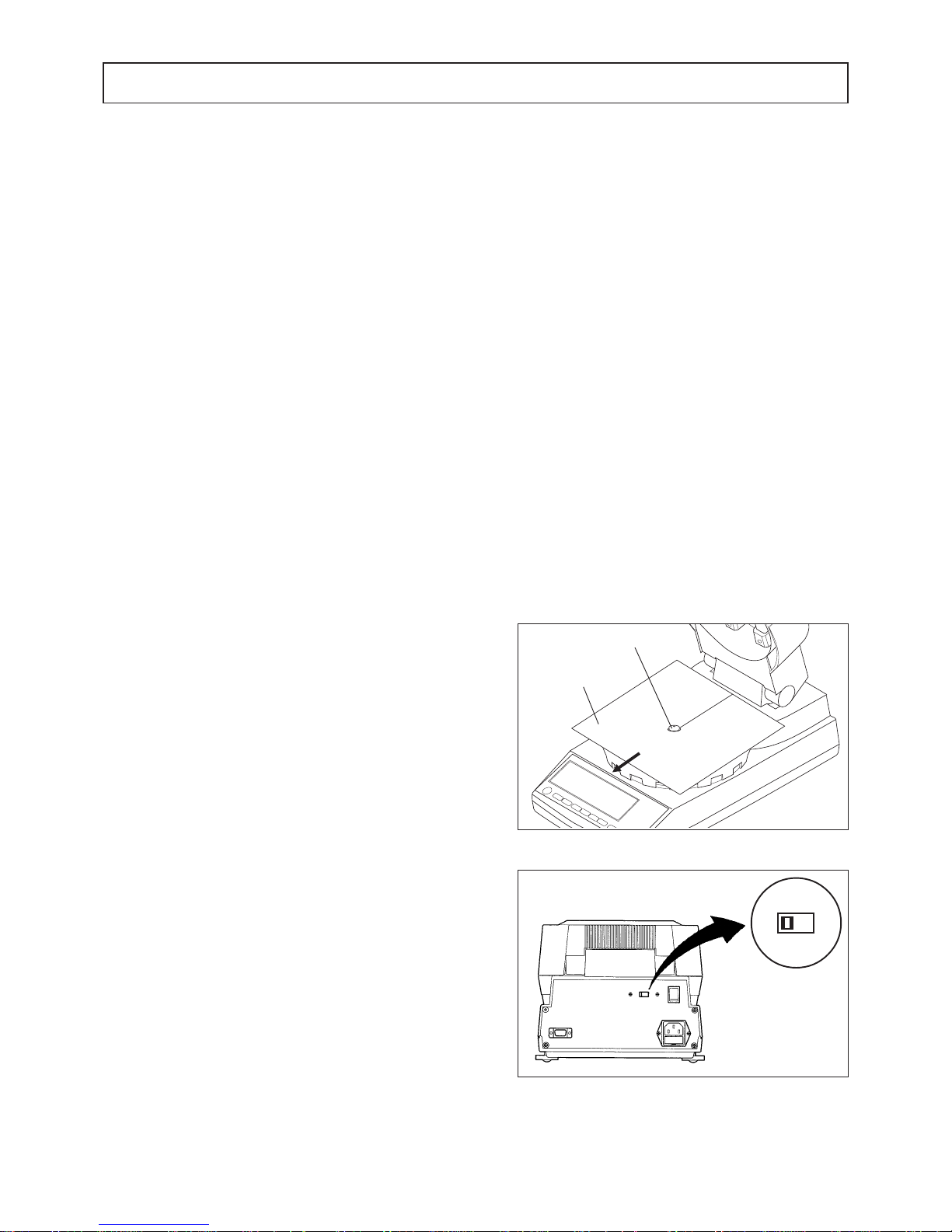
1 Opening the package
Open the package and check to make sure all listed
items are included.
Scale stopper
Sample dish panel
2 Installing the main unit
•Place the main unit on a flat, stable surface where
it will not be subject to vibrations or exposed to
drafts or breezes.
• Install the main unit so that it is at least 10cm from
the wall both to the front and back and to the left
and right. Make sure there is a space at least 30cm
above the top of the heater cover.
•Do not use it in a closed installation environment.
Depending on the sample, heating may produce
hazardous substances. Install it in a location that
can be adequately ventilated.
4 Checking the power settings
Check the power conversion switch located on the
rear of the main unit to make sure that it is currently
set to the proper voltage setting for your power
source.
* Note that an error will occur if this switch is not set to
a position matching the power source being used.
Power conversion
switch
3 Removing the stopper from the sample dish panel
When using the unit for the first time after purchase,
remove the scale stopper attached below the sample
dish panel as indicated in the accompanying
diagram.
〜
〜
100V 220V
120V 240V
Page 15
15
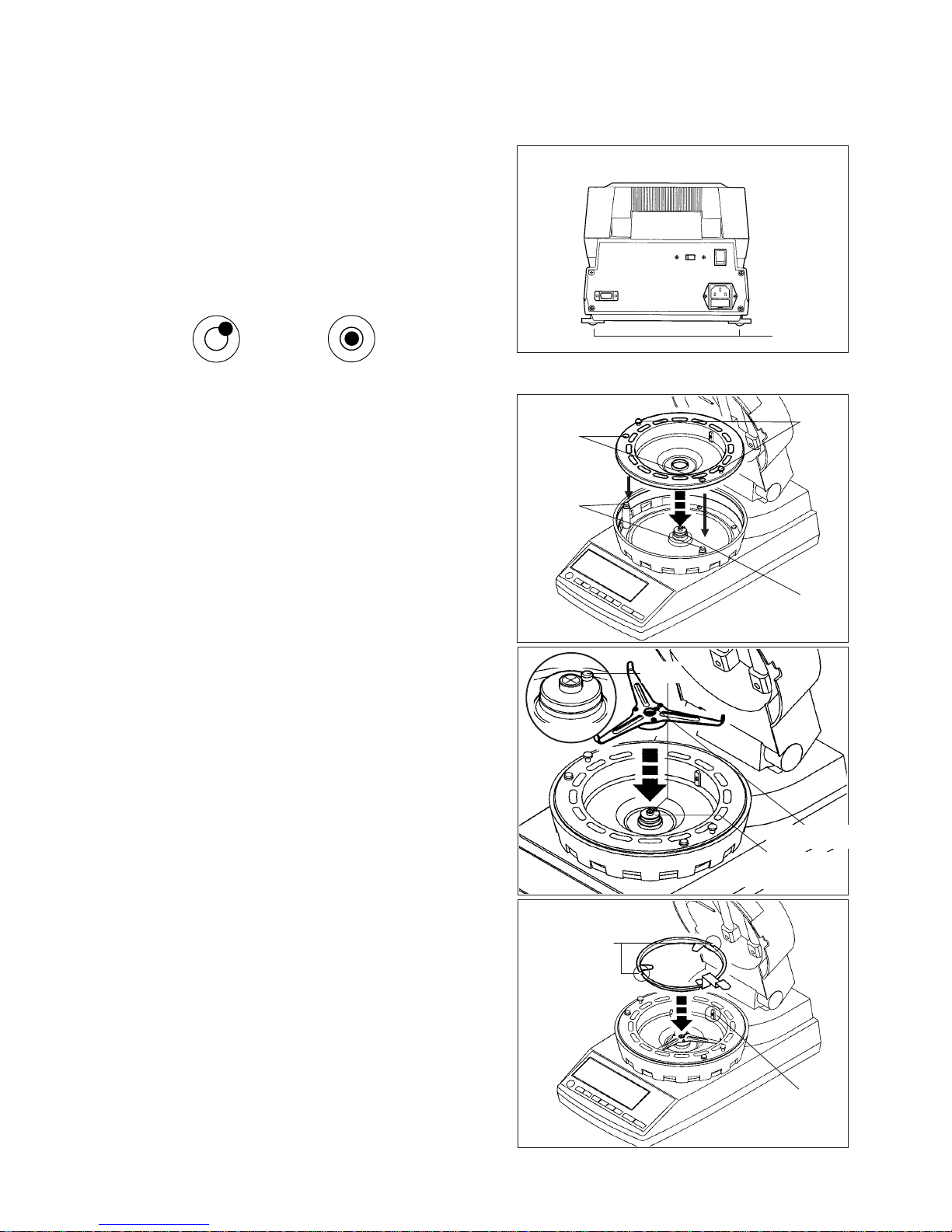
5 Level is located to the left of the control panel.
Knobs
Round
holes
Stays
Sample dish panel
Grooves
Stay
8 Attaching the sample dish handler
Next, attach the sample dish handler, being sure
when you do so that the grooves of the handler fit
smoothly over the projection located at the rear of the
wind shield.
* While the sample dish handler is shown with the
handle being placed to the right in the diagram shown
here, the handle may be placed either to the left or
right, and you should accordingly place the handle in
the position you find easiest to use.
7 Attaching the sample dish tray
Place the sample dish tray gently into the sample
dish panel at the center of the main unit, being sure
when you do so that the round hole of the sample
dish tray fit smoothly over the stay on the sample
dish panel.
6 Installing the wind shield
Open the lid of the heater, hold the wind shield by the
knobs on the top, and place it on top of the sample
dish panel so that the two round holes in the wind
shield fit over the stays of the sample dish panel.
*Place the wind shield firmly into position so that it
does not come into contact with the black projection
located at the center of the main unit (sample dish
panel).
5 Ensuring that the unit is level
Turn the two height adjustment legs located at both
sides of the lower rear of the unit to adjust until the
level bubble falls within the red circle.
* The level is located to the left of the control panel. The
tester is perfectly level if the bubble appears in the
center of the red circle when viewed from directly
above.
Not level Level
Bubble
⇒
Height
adjustment
legs
Sample dish
panel
Round hole
Stays
Page 16
16
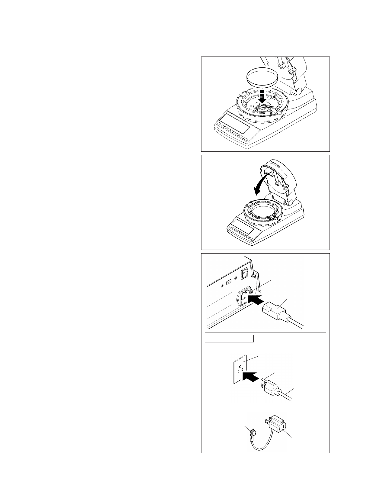
9 Placing the sample dish into the tester
Please the sample dish gently down onto the sample
dish tray.
0 Close the heater lid
! Connecting the power cord
Insert the female end of the power cord into the
power inlet located at the rear of he unit. Then insert
the power plug into the power outlet. Connect the
plug to a power outlet in an easily accessed location
so that it can be pulled out immediately if there are
any problems with the infrared moisture tester. And
be sure to always ground the main unit. If there is no
grounding terminal on the power outlet, use a
grounding adapter. The shape of the power plug
varies in different countries. Use a power cord set
suited to the shape of the plug that you actually use.
@ Connecting the printer (sold separately)
If you are using a printer, connect the printer using
the provided printer interface cable. For instructions
on how to use the printer, see the separately
provided VZ-330 Printer User’s Manual.
Assembly is now complete.
* Some parts must be oriented in a fixed direction for
assembly. Note that placing parts in the wrong
direction may result in errors in operation or in
erroneous readings being obtained, and that you
should take care that all parts are put into place in their
proper positions.
Power cord inlet
Connector
Installation method
• When grounding with the connector
• When grounding with a grounding adapter
Power cord
Grounding terminal
Grounding terminal equipped
power outlet
Grounding adapter
Grounding by screwing in
the grounding adapter
Page 17
17
7.
Tips on how to ensure accurate measurements
Points to remember when conducting multiple measurements in succession
Placing a sample onto a sample dish which is already warm may cause moisture from the sample to
evaporate before measuring is begun and cause errors to occur in measurement. Always be sure to
use a cool sample dish when performing a second or subsequent measurements.
You should also take care to allow an even amount of time to elapse between measurements, as
errors in measurement may occur if the temperature of the internal scale of the unit does not remain
at a constant level.
*Two sample dishes and two sample dish handlers are included.
Use of sample dishes and aluminum foil sheets
It is impossible to obtain accurate measurements if residue from the sample last measured remains
on the sample dish. To avoid such problems, either wipe the sample dish clean of any dirt or soil (see
“15. Maintenance” on p. 64 for further instructions) or use disposable aluminum foil sheets to protect
against residues, soil, or dirt.
*Twenty disposable aluminum foil sheets are included with the unit.
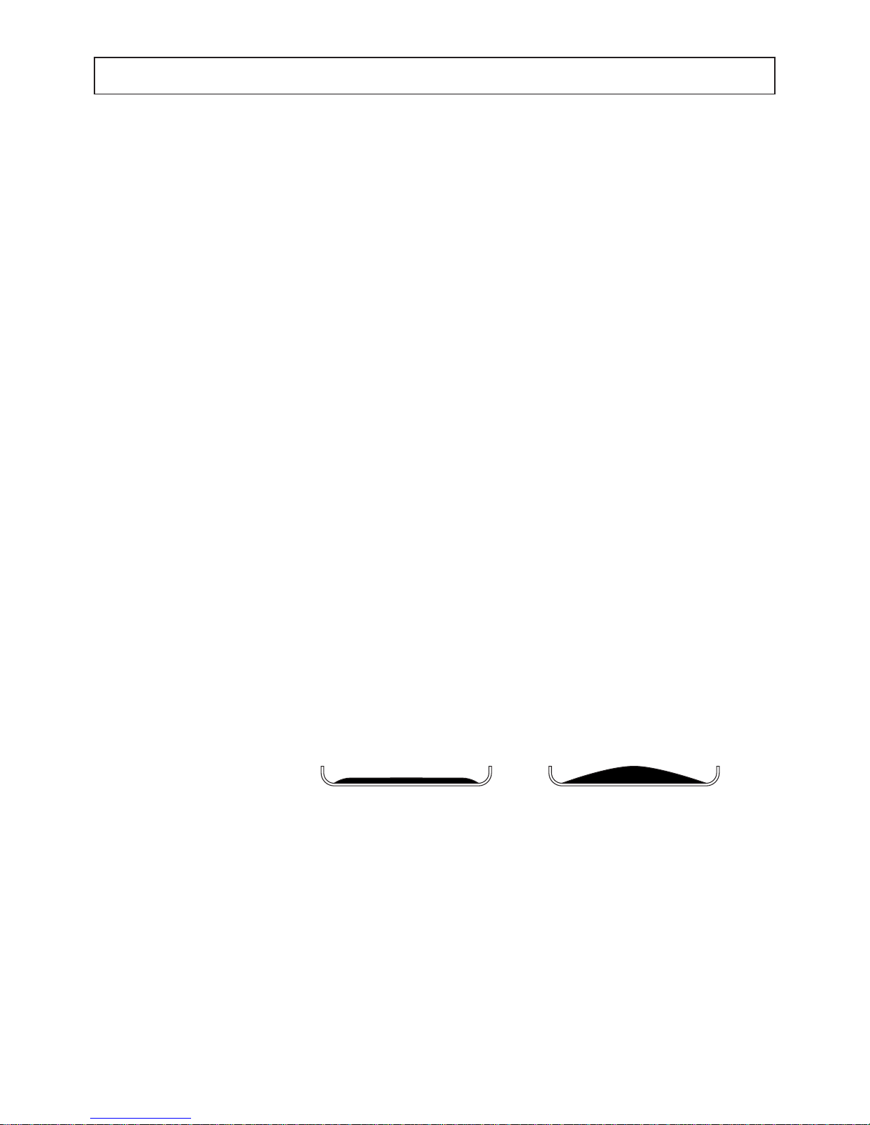
Quantity and placement of powdered, particulate and viscous sample materials
The easier it is to heat the surface of a sample material, the easier it is for projecting portions of the
material or for material at the top of a mound of material to become burnt. If the material is placed in
a mound on the dish or if the material is not flat and evenly laid out, this is likely to happen, thus
making it impossible to obtain accurate measurements.
Note that while the precision of measurement improves the more flatly and evenly samples are
placed and the higher the amount of sample material used, the quantity of sample material used is
too great if the surface becomes burned before lower layers are fully dried.
Always be sure to lay out samples flatly and evenly as indicated in the diagram below.
Measuring liquid samples
Virtually all liquid materials will coagulate after being dried, and when working with such materials
they should be placed on the provided sheets of aluminum foil. Note that these aluminum foil sheets
are water-permeable, thus making it possible to obtain wide and even placement and making them
effective for use in shortening measuring times and obtaining accurate measurements.
Depending on the sample in question, the use of sand to speed up drying (Silica sand or ocean sand
with a mesh of 20 or so) may be even more effective.
Proper placement
Incorrect placement
Page 18

18
Crushing samples consisting of large particles before measuring
If samples consisting of large particles are measured in their original condition it not only takes longer
for drying to completed to the center, but also may result in problems such as the surface of the
sample becoming burned, thus making it impossible to obtain accurate measurements.
For this reason you should always crush samples to an appropriate size.
The TQ-100 Sample Crusher (sold separately) is excellent for this pur pose.
TQ-100 Sample Crusher
Page 19
19
8. How to Conduct Measurements
Before beginning a measurement, check to make sure that there is nothing remaining in the
sample dish. Also be sure that all parts of the main unit are firmly fixed in place and be sure that
the heater lid has been closed firmly before starting to perform measurements.
Also be sure to check on a regular basis that the main unit is level and readjust the height adjustment legs if necessary. (See “6. Assembly and Installation of Main Unit” on p. 14 for instructions on
how to do so.)
Display
* Display will show default settings at the
time of shipment. (See p. 24, “9-2-1
Selecting the CONDITIONS (Measuring
conditions storage area)”.)
Operating instructions
1 Turn on the power switch
Turn on the power switch located at the rear of the unit.
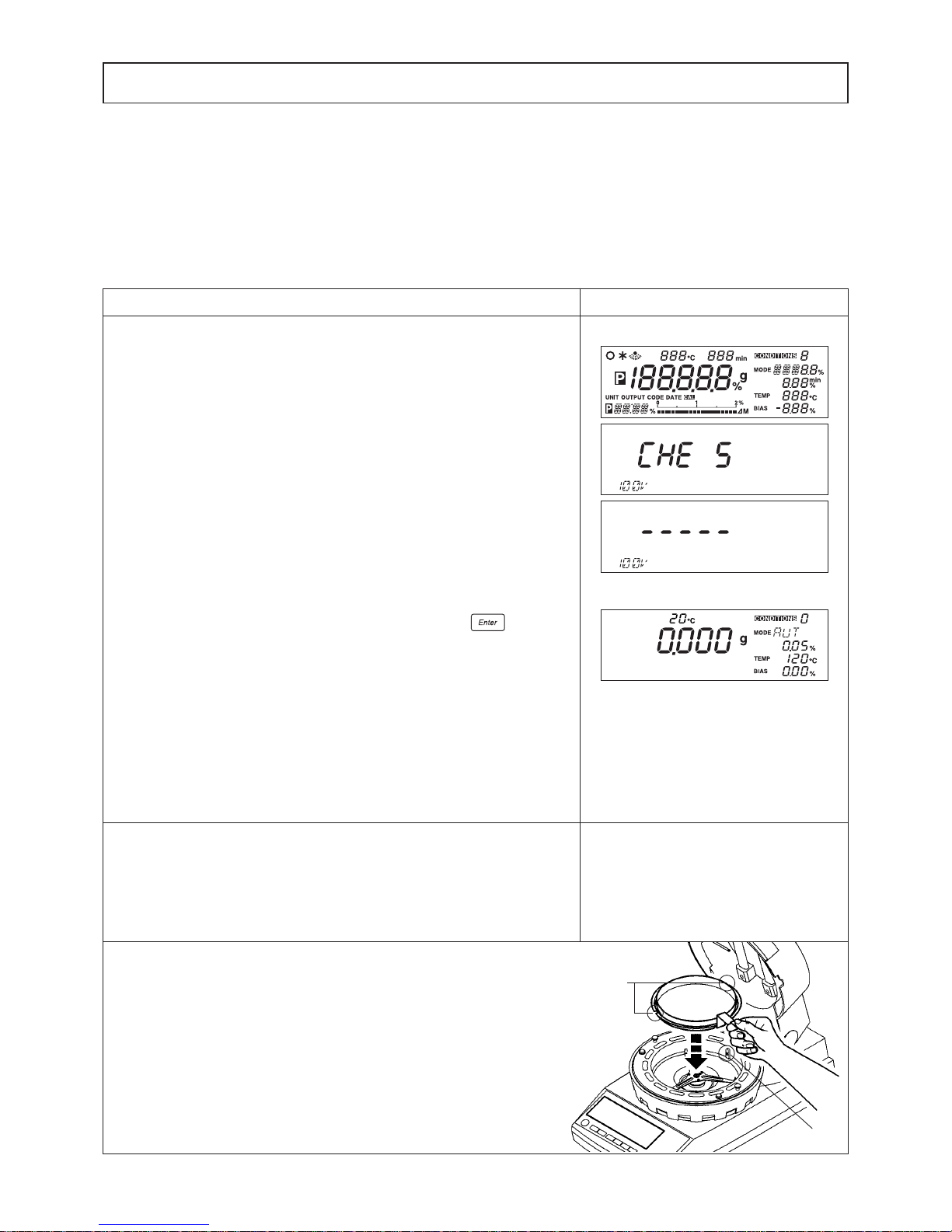
When you turn on the power for the first time after purchasing your tester, a
tone will sound, the display will light up with all items lit and then change to
display first ‘CHE5’ and then a string of dashes (i.e., ‘- - - - -’).
At the bottom left of the display will be displayed the power settings
specified (as described in step 4 of “6. Assembly and Installation of Main
Unit” on p. 14) with the display reading ‘100V’ when the power settings have
been set to 100~120V and reading ‘220V’ when they have been set to
220~240V.
If using the tester in a country that does not use 100V power, then this is the
time when you should specify the power settings to be used. (See step 3 of
“10-2-8 Specifying the power settings” on p. 47 for instruction on how to do
so.)
* When using the tester in Japan, the settings should be left unchanged. Check
to make sure that the display reads ‘100V’ and then press the key.
As the power setting continues to be displayed in the lower left of the display,
the center of the display will change to display ‘CHE4’, ‘CHE3’, … , ‘CHE0’ and a
tone will sound and the display will change to weight reading display mode.
* When the power is turned on for the second or subsequent times, a tone will
sound, the display will light up with all items lit, the display will change to
display ‘CHE5’, ‘CHE4’, … , ‘CHE0’ while the currently specified power setting is
displayed, and then a tone will sound again and the display will change to
weight reading display mode.
* Note that it is recommended that you always turn on the tester about half an
hour before use in order to obtain consistent measurements.
2 Specifying settings
When performing measurements for the first time, or when you wish to
change current settings before measuring, then you should specify the
settings required for measuring here. (See “9. Specifying Measuring
Conditions” on p. 23 and “10. Menu settings” on p. 36 for instructions on
how to do so.)
3 Placing the sample dish in the tester
Open the heater lid, place the sample dish on the handler, and place the
handler into the tester, being sure when you do so that the grooves of the
handler fit smoothly over the projection located at the rear of the wind shield.
* If you have already placed the sample dish and handler (as described in “6.
Assembly and Installation of Main Unit”) then proceed directly to the next step.
* When using an aluminum foil sheet or other wrapping because of the nature of
the sample being measured, place the wrapping on top of the sample dish.
.
.
.
Grooves
Stays
Page 20
20
DisplayOperating instructions
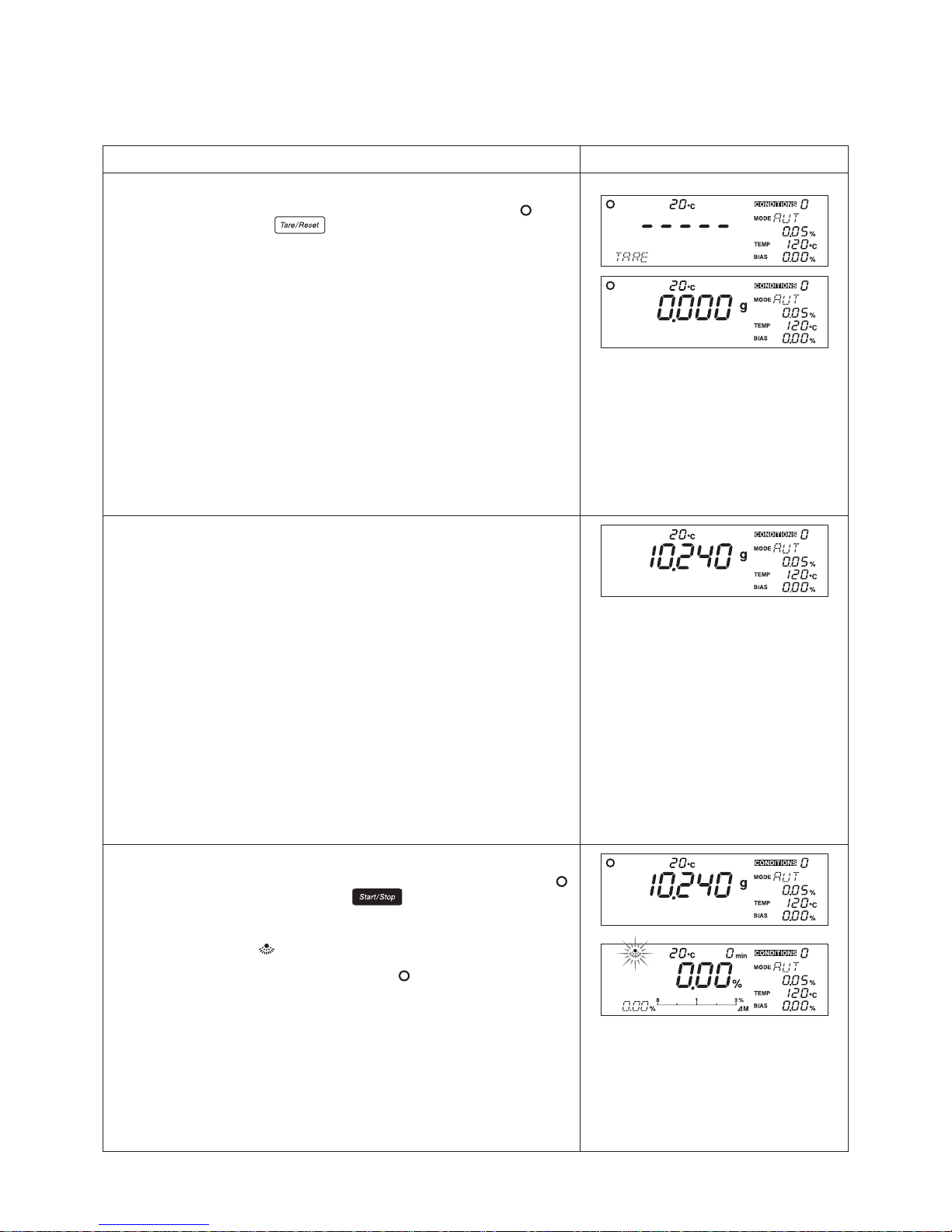
4 Performing a tare
Shut the heater lid, check to make sure that the steady-state mark (
) is
displayed, and press the
key. A series of hyphens and the word
‘TARE’ will be displayed, the sample dish will move vertically and a tare will
be performed. A sharp tone will then sound and the word ‘TARE’ will
disappear from the display, a weight of ‘0.000 g’ will be displayed and the
tare will then be complete.
* Always be sure that the heater lid is closed when performing a tare. Also make
sure that the tester is not exposed to drafts or breezes, or subjected to any
vibrations when a tare is being performed.
5 Placing a sample in the tester
Open the lid to the heater and place the sample inside.
Be sure to place the sample as flatly as possible into the tester so that heat
is applied evenly to the sample during measurement. (See “7. Tips on how
to ensure accurate measurements” on p. 17 for further information.)
6 Beginning measurement
Close the lid of the heater, check to make sure that the stability indicator (
)
is being displayed, and then press the
key. The display will switch
from a display of the weight (i.e., grams) to a percentage display and the
measuring time will be displayed.
The heating indicator ( ) will start to flash and drying will begin.
* There may be times when the stability indicator ( ) is not displayed because of
external vibrations or drafts or breezes. While it is possible to perform
measurements at such times, there may be cases when it is impossible to
obtain accurate measurements at such times. You should always be sure to
conduct measurements in a location as free as possible of vibrations, drafts,
breezes, or any other harmful influences.
Page 21
21
DisplayOperating instructions
* Never open the lid to the heater while a measurement is in progress. Doing so
is not only hazardous but also could contribute to making it impossible to
obtain accurate measurements.
If it is absolutely necessary to open the lid to the heater while a measurement is
in progress to view the sample material (or for some other reason) limit the time
the lid is opened to 15 seconds or less. (A warning buzzer will sound 10
seconds after the lid is opened and if the lid remains open for more than 15
seconds, the measurement operation will be aborted and an ‘ER306’ error code
will be displayed.)
* Pressing the
key while the heater lid is open will cause a safety alert
buzzer to sound and measuring to be stopped.
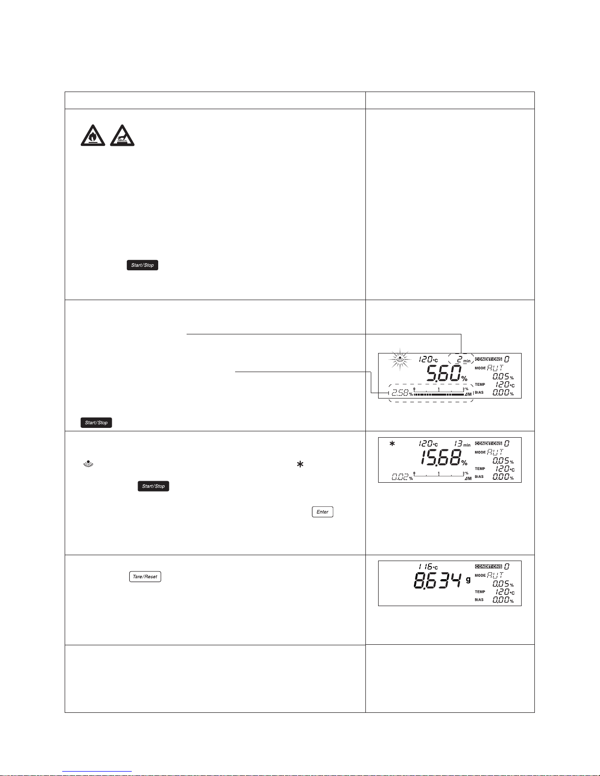
7 Measuring time display
While a measurement is being performed, the amount of time elapsed
will be displayed in minutes.
* The change in moisture content over each 30-second interval is displayed
numerically and in scalar format (where the scalar display may display a
maximum change of 2 percent/30 seconds).
* Weight is performed automatically once per minute (or once every 30 seconds
when near the end of the measuring time) while measuring moisture content.
* To stop measuring when in the midst of a measuring operation, press the
key.
8 Completion of measurement
When the measuring operation has been completed, the heating indicator
(
) will disappear, the measurement completed indicator ( ) will be
displayed, and a tone will ring for a period of 10 seconds. To turn off the
tone, press the
key. The results of the measurement will be
displayed and remain displayed on the display.
* If the unit is connected to a printer (sold separately), pressing the key
while a hold message is being displayed will cause the signature field to be
printed. (See “13-1 Sample Printer Output” on p. 56 for further information.)
9 Resetting the display
Pressing the
key at this point causes the display of the results of
the measurement (i.e., moisture content) to disappear and be replaced by a
display of the weight of the sample after drying.
* Note that a reset cannot be performed until the completion tone has stopped
ringing.
0 Disposing of samples after measurement
Open the lid to the heater, raise the handler vertically, remove the sample
dish, and dispose of the sample.
* Note that the sample and sample dish may be very hot and you should
accordingly be careful in handling them at this time.
Page 22
22
Operating instructions
! Prepairing to perform the next measurement
Leave the lid to the heater open to allow the tester to cool. When performing
sequential measurements, leave an interval of about 1-2 minutes between
each measurement and make sure that the tester has cooled before
proceeding to the next measurement. You should also keep a spare
(cooled) sample dish available to use in the next measurement. (See “7.
Tips on how to ensure accurate measurements” on p. 17 for further
information.)
When ready, return to step 3 and begin the next measurement.
@ Turning off the power
When all the measurements have been completed, pull the power plug from
the power outlet. And when not using the main unit, always pull the power
plug from the power outlet.
Display
Page 23
23
9. Specifying Measuring Conditions
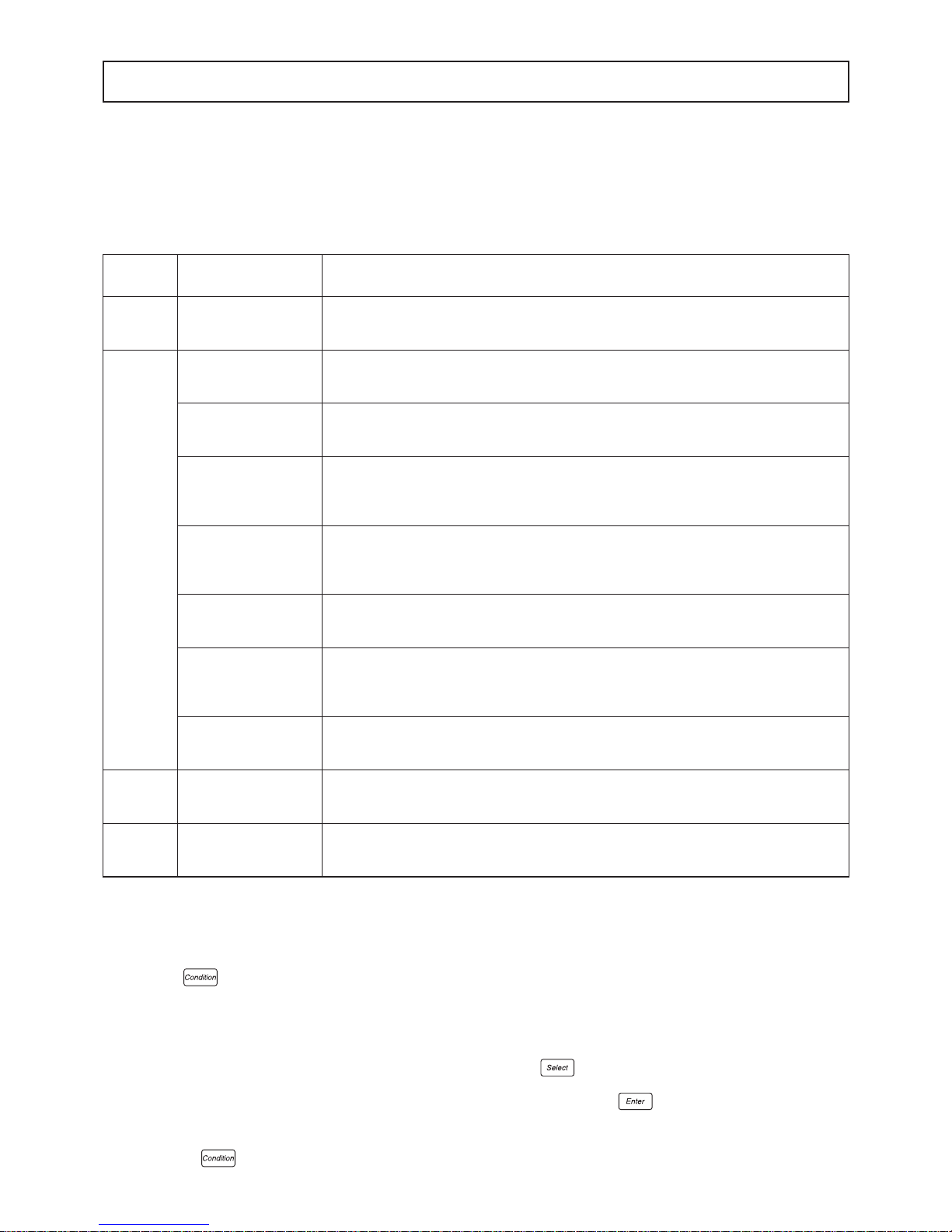
When using this tester to measure moisture or solid content, it is necessary to first specify the conditions
(e.g., drying temperature or measuring mode) to be used in performing the measurement. The settings
which may be specified are as described below.
When necessary, it is also possible to save sets of measuring conditions (i.e., drying temperature, measuring mode, and bias).
9-1 Types of Settings
Description
Used to select the area to which measuring conditions are to be stored. There are 10 storage areas labeled
from 0 to 9. (See p. 24, “9-2-1 Selecting the CONDITIONS (Measuring conditions storage area)”.)
In automatic halting mode, measuring is brought to a halt whenever the change in moisture content over two
consecutive 30-second periods falls below the specified conditions for automatic halting. (For further
information, see 9-2-2 “1) Specifying settings for AUTO (Automatic halting) mode” on p. 25.)
Causes measuring to be completed when the specified amount of time has elapsed. (For further information,
see 9-2-2 “2) Specifying settings for TIME (Timed halting) mode” on p. 26.)
Causes the sample material to be rapidly dried until the amount of change in moisture content over a period of
30 seconds falls below the specified quantity and for drying to then be continued at the specified drying
temperature. (For further information, see 9-2-2 “3) Specifying settings for RAPID (High-speed drying) mode”
on p. 27.)
In low-speed drying mode, the temperature is raised more gradually than when performing measurements
under normal conditions, with it taking about 5 minutes from the time when measuring begins until the
temperature reaches the specified drying temperature. (For further information, see 9-2-2 “4) Specifying
settings for SLOW (Low-speed drying) mode” on p. 29.)
In stepped drying mode it is possible to specify a separate drying temperature and separate measuring time
over up to 5 step intervals. (For further information, see 9-2-2 “5) Specifying settings for STEP (Stepped
drying) mode” on p. 30.)
Comparative measuring mode is used to measure the bias (i.e., the difference between the measurement
corresponding to that obtained in automatic halting mode and the predicted measurement value) needed in
order to perform measurements in predictive measuring mode. (For further information, see 9-2-2 “6)
Specifying settings for COMPARE (Comparative measuring) mode” on p. 32.)
In predictive measuring mode, the intermediate results of drying are used to predict future changes and to
calculate the predicted measurement and thereby shorten the amount of time used in measurement. (For
further information, see 9-2-2 “7) Specifying settings for PREDICT (Predictive measuring) mode” on p. 33.)
This parameter may be used to specify the drying temperature. The temperature may be set anywhere within
a range of from 30°C to 180°C in 1-degree increments. (For further information, see “9-2-3 TEMP (Drying
temperature)” on p. 34.)
This parameter is used to specify a numeric value to be used to correct measurements for bias. A bias
anywhere in the range of from –9.99% to 9.99% may be specified in 0.01% increments. (For further
information, see “9-2-4 Bias” on p. 35.)
Display during
specification of setting
CONDITION 0~9
(Measuring conditions
storage areas 0~9)
AUT
(AUTO: Automatic halting
mode)
TIM
(TIME: Timed halting
mode)
RPD
(RAPID: High-speed drying
mode)
SLW
(SLOW: Low-speed drying
mode)
STP
(STEP: Stepped drying
mode)
CMP
(COMPARE: Comparative
measuring mode)
PRD
(PREDICT: Predictive
measuring mode)
○○○
○.○○
Setting
CONDITION
MODE
(Measuring
mode)
TEMP
(Drying
temperature)
BIAS
(Bias value)
9-2 Descriptions of Individual Measuring Condition Settings
For a detailed description of individual measuring condition settings, see the instructions on how to specify
the settings for each item in subsection 9-2-1 and subsequent subsections.
1 To start specifying measuring condition settings:
Press the
key at a time when the display shows a weight reading.
2 If any password other than the default password of ‘0000’ has been specified, then a ‘PASS’ message will be displayed in
the weight display area. When this message is displayed, follow the instructions provided on p. 46, “10-2-7 Specifying a
password”, to enter a password. If the password entered is incorrect, the display will return to the weight display.
3 Selecting individual measuring conditions:
First a ‘CONDITIONS’ message will flash on the display. Pressing the
key at this time causes the flashing item to
change in sequence from MODE to TEMP to BIAS to CONDITIONS and back to MODE and so on each time the key is
pressed. When the item for which you wish to specify settings is flashing, press the key. At this point it will be
possible to specify the settings for the flashing item.
4 To finish specifying measuring condition settings:
Pressing the
key at a time when any settings item is flashing causes the settings specified to take effect and cause
the display to return to the normal weight display.
Page 24
24
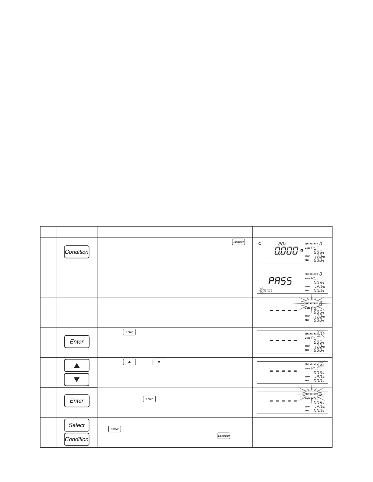
9-2-1 Selecting the CONDITIONS (Measuring conditions storage area)
Below is described the procedure used to select the area in which measuring conditions are to be
saved.
This operation causes the measuring mode, drying temperature, bias, and other currently specified
measuring conditions to be saved to the selected area.
* At the time of shipment, the following settings are stored in measuring conditions storage areas 0~9:
Measurement standard : Wet Base
Drying temperature : 120°C
Measuring mode : Automatic halting mode (Change in water content of 0.05% over
30seconds)
Bias : 0.00%
Specifying settings for the CONDITIONS (Measuring conditions storage area)
Key(s) used
Operating instructions
With the display displaying the weight in grams, press the
key.
If a password has been specified, the message ‘PASS’ will be
displayed to indicate that a password should be entered. Follow
the instructions in “10-2-7 Specifying a password” on p. 46 to
enter the password.
The ‘CONDITIONS’ display area will begin to flash.
Press the key. This will cause the highlight to move to the
measuring conditions area number and for the measuring
conditions area number to begin to flash.
Press the key or key to select a measuring
conditions area number from 0 to 9. In this example, we selected
area number ‘5’.
When the desired measuring conditions area number starts
flashing, press the
key. The selected measuring conditions
area number will change from a flashing to a constantly lit display
and the ‘CONDITIONS’ message will begin to flash instead.
If you wish to specify other measuring conditions settings, press
the
key to select the setting to be specified. To exit from
specifying measuring conditions settings, press the
key
instead.
Step
1
2
3
4
5
6
7
Display
Page 25
25
9-2-2 Selecting the MODE (Measuring mode)
The ‘MODE’ (measuring mode) setting is used to specify the conditions under which measuring is to be
completed. As shown in the table in subsection “9-1 Types of Settings”, the mode may be set to one of seven
methods.
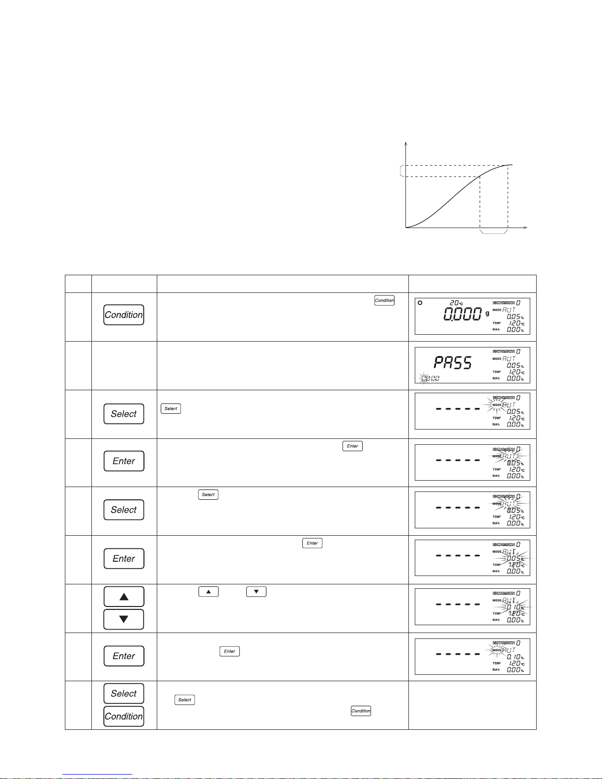
1) Specifying settings for AUTO (Automatic halting) mode
In automatic mode, measurement is brought to completion when
the amount of change in moisture content over a period of 30
seconds falls to a level below a specified threshold level. The
automatic halting threshold level may be specified in 0.01-percent
increments from 0.01 to 0.1percent.
Specifying a smaller percentage causes measurements to approach a
point of equilibrium, but more time is then required for measurement.
Specifying a higher percentage lessens the amount of time required for
measurement, but measuring is completed while there may still be a wide
variation in measurements. The automatic halting conditions should be
specified in accordance with your objectives and the type of sample being
measured.
Change in
moisture
content ∆M
Measurement (%)
30 seconds
Measuring time
Key(s) used
Operating instructions
With the display displaying the weight in grams, press the
key.
If a password has been specified, the message ‘PASS’ will be
displayed to indicate that a password should be entered. Follow
the instructions in “10-2-7 Specifying a password” on p. 46 to
enter the password.
The ‘CONDITIONS’ display area will begin to flash. Press the
key until ‘MODE’ begins to flash.
With the ‘MODE’ display area flashing, press the key. This
will cause the highlight to shift to measuring mode selection and
for the currently specified measuring mode to begin flashing.
Press the key until ‘AUT’ begins to flash.
* Since ‘AUT’ will already be flashing at the point, proceed directly
to the next step.
When ‘AUT’ begins to flash, press the key. This will cause
the automatic halting mode settings to become active and for the
automatic halt conditions (i.e., amount of change in moisture
content per 30 seconds) to begin flashing.
Press the
key or key to select the automatic halt
conditions. Note that here we specify a setting of 0.1 percent.
When the desired automatic halt conditions setting begins to
flash, press the
key. The automatic halt conditions setting
will change from a flashing to a constantly lit display and ‘MODE’
will begin to flash instead.
If you wish to specify other measuring conditions settings, press
the
key to select the setting to be specified. To exit from
specifying measuring conditions settings, press the
key
instead.
Step
1
2
3
4
5
6
7
8
9
Display
Page 26
26
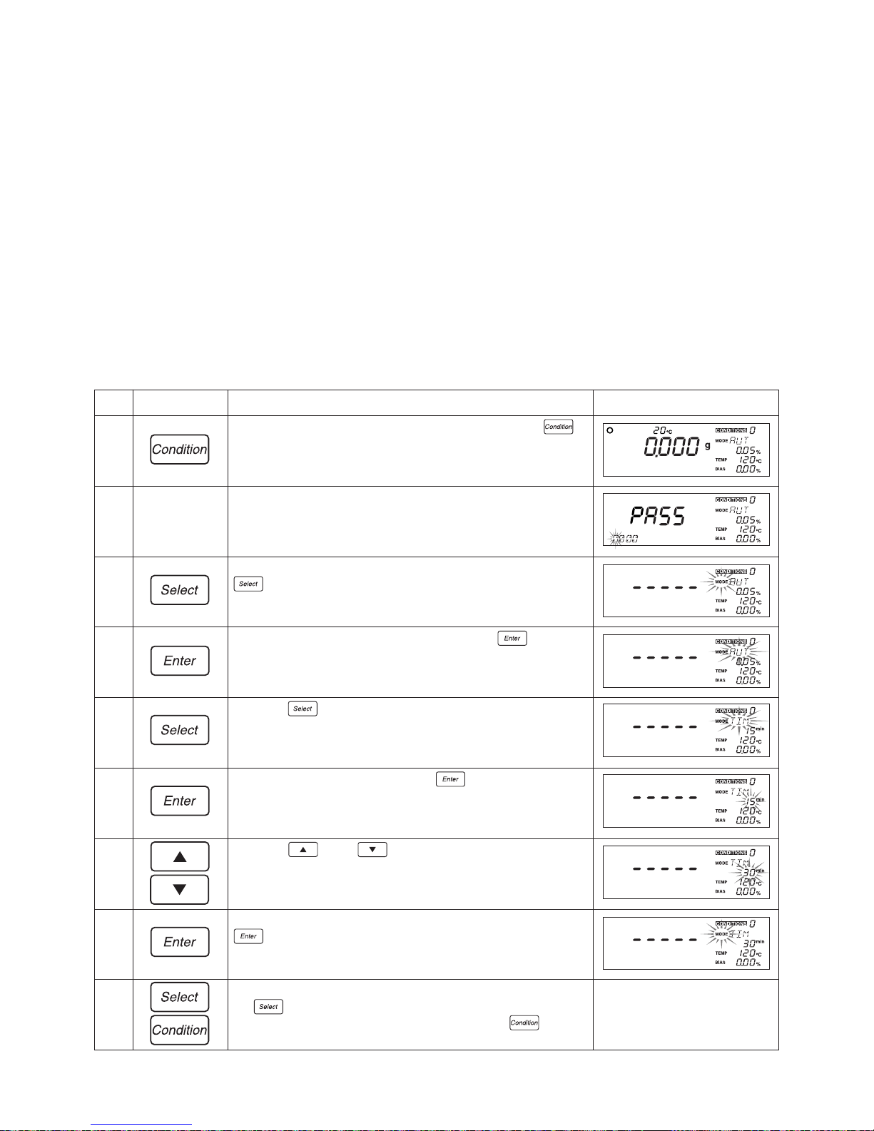
2) Specifying settings for TIME (Timed halting) mode
In timed halting mode, the measuring time is specified before the test and the sample is dried to determine
its moisture (or solid) content. When the specified measuring time is reached, the test is halted.
Measuring time may be specified in 1-minute increments anywhere in a range from 1 to 240 minutes or
measuring may be specified to be performed over a continuous period of 12 hours.
Key(s) used Operating instructions
With the display displaying the weight in grams, press the
key.
If a password has been specified, the message ‘PASS’ will be
displayed to indicate that a password should be entered. Follow
the instructions in “10-2-7 Specifying a password” on p. 46 to
enter the password.
The ‘CONDITIONS’ display area will begin to flash. Press the
key until ‘MODE’ begins to flash.
With the ‘MODE’ display area flashing, press the key. This
will cause the highlight to shift to measuring mode selection and
for the currently specified measuring mode to begin flashing.
Press the key until ‘TIM’ begins to flash.
* If ‘TIM’ is already flashing, then proceed directly on to the next
step.
When ‘TIM’ begins to flash, press the key. This will cause
the measuring time settings to become active and for the currently
specified measuring time to begin to flash.
Press the key or key to select the desired measuring
time. Note that here a time of ‘30 minutes’ is specified.
When the desired measuring time begins flashing, press the
key. The specified measuring time will change from a
flashing to a constantly lit display and ‘MODE’ will begin to flash
instead.
If you wish to specify other measuring conditions settings, press
the
key to select the setting to be specified. To exit from
specifying measuring conditions settings, press the
key
instead.
Step
1
2
3
4
5
6
7
8
9
Display
Page 27
27
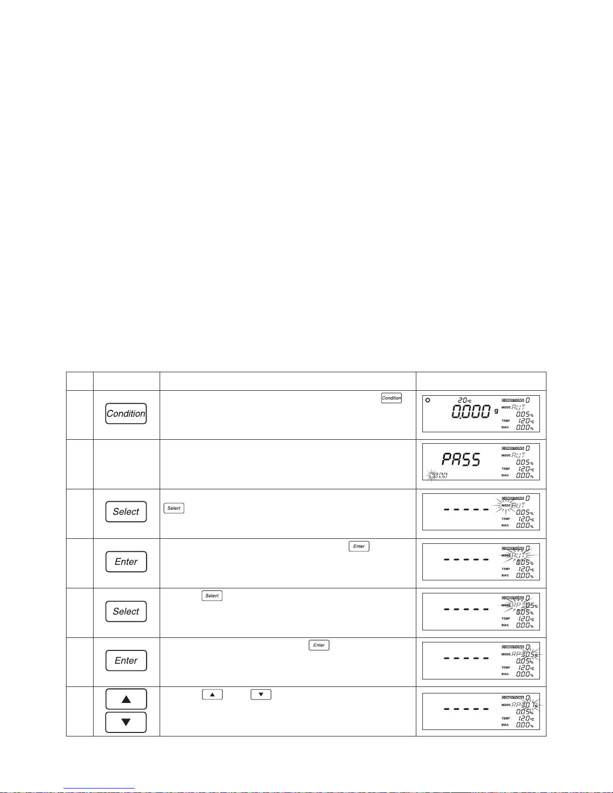
3) Specifying settings for RAPID (High-speed drying) mode
During the initial phase of measurement, the material is dried at a temperature higher than the specified
drying temperature to speed up drying and reduce the amount of time required for performing
measurements. Once drying has proceeded to a sufficient point, the temperature is returned to the specified
temperature and drying is continued at that temperature to help prevent burning.
In this mode, it is necessary to specify the drying temperature to be used during the initial phase of
measurement (i.e., the rapid drying temperature) and the amount of change in moisture content over a 30second interval needed to maintain that temperature (i.e., the conditions under which the rapid drying
temperature is to be maintained). Rapid drying will continue to be performed until the change in moisture
content over a 30-second interval (∆M) falls to a level below the specified level at which rapid drying
conditions are to be maintained, and after that drying will continue at the specified drying temperature.
The amount of change in moisture content over which rapid drying is to be continued may be specified in
0.1-percent increments from 0.1 to 9.9 percent.
* Note that a higher value should be specified for the rapid drying temperature than the regular drying
temperature.
* Note that it may take a considerable amount of time for the temperature to be lowered from the rapid drying
temperature to the regular drying temperature.
Specifying a relatively low degree of change in moisture content or specifying a high rapid drying temperature
may reduce the amount of time required to perform a measurement, but depending on the sample material
being measured doing so could result in the material becoming burnt or make it impossible to obtain accurate
measurements. Conversely, specifying a relatively high degree of change in moisture content or specifying a
low rapid drying temperature could make it difficult to obtain the effects expected from performing rapid drying.
Either AUTO (automatic halting) or TIME (timed halting) may be specified as the halt condition.
Key(s) used Operating instructions
With the display displaying the weight in grams, press the
key.
If a password has been specified, the message ‘PASS’ will be
displayed to indicate that a password should be entered. Follow
the instructions in “10-2-7 Specifying a password” on p. 46 to
enter the password.
The ‘CONDITIONS’ display area will begin to flash. Press the
key until ‘MODE’ begins to flash.
With the ‘MODE’ display area flashing, press the key. This
will cause the highlight to shift to measuring mode selection and
for the currently specified measuring mode to begin flashing.
Press the key until ‘RPD’ begins to flash.
* If ‘RPD’ is already flashing, then proceed directly on to the next
step.
When ‘RPD’ begins to flash, press the key. The highlight
will then be transferred to the specification of the rapid drying
temperature and the numeric display will begin to flash.
Press the key or key to select the rapid drying
temperature maintenance conditions. In this example we have
specified a degree of change of 0.7%.
Step
1
2
3
4
5
6
7
Display
Page 28
28
DisplayKey(s) used Operating instructions
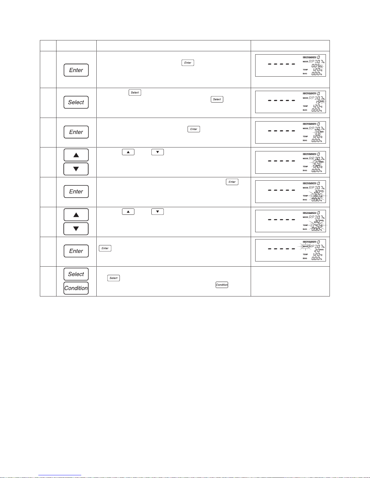
When the desired the rapid drying temperature maintenance
conditions begins to flash, press the
key. The high-speed
settings will then be set and the highlight will shift to the selection
of the halting conditions. The units area for timed halting mode
(‘min’) or automatic halting mode (‘%’) will begin to flash.
Pressing the
key will cause the units to switch between
minutes (‘min’) and a percentage (‘%’). Press the
key until
the desired units are displayed.
When the desired units for the halting conditions (i.e., minutes or
a percentage) begin to flash, press the
key. This will cause
the highlight to shift to the specification of the halting conditions
and the numerical field begin to flash.
Press the
key or key to select the desired halting
conditions. In this example, timed halting (20 minutes) is
specified.
When the desired time or percentage flashes, press the
key. The temperature field with a value of 180°C or the rapid
drying temperature last specified will begin to flash. (The initial
default values is 180°C.)
Press the
key or key to select the rapid drying
temperature. In this example the temperature is set to 140°C.
When the desired rapid drying temperature is displayed, press the
key. The press the ‘MODE’ field will then begin to flash.
If you wish to specify other measuring conditions settings, press
the
key to select the setting to be specified. To exit from
specifying measuring conditions settings, press the
key
instead.
Step
8
9
0
!
@
#
$
%
Page 29
29
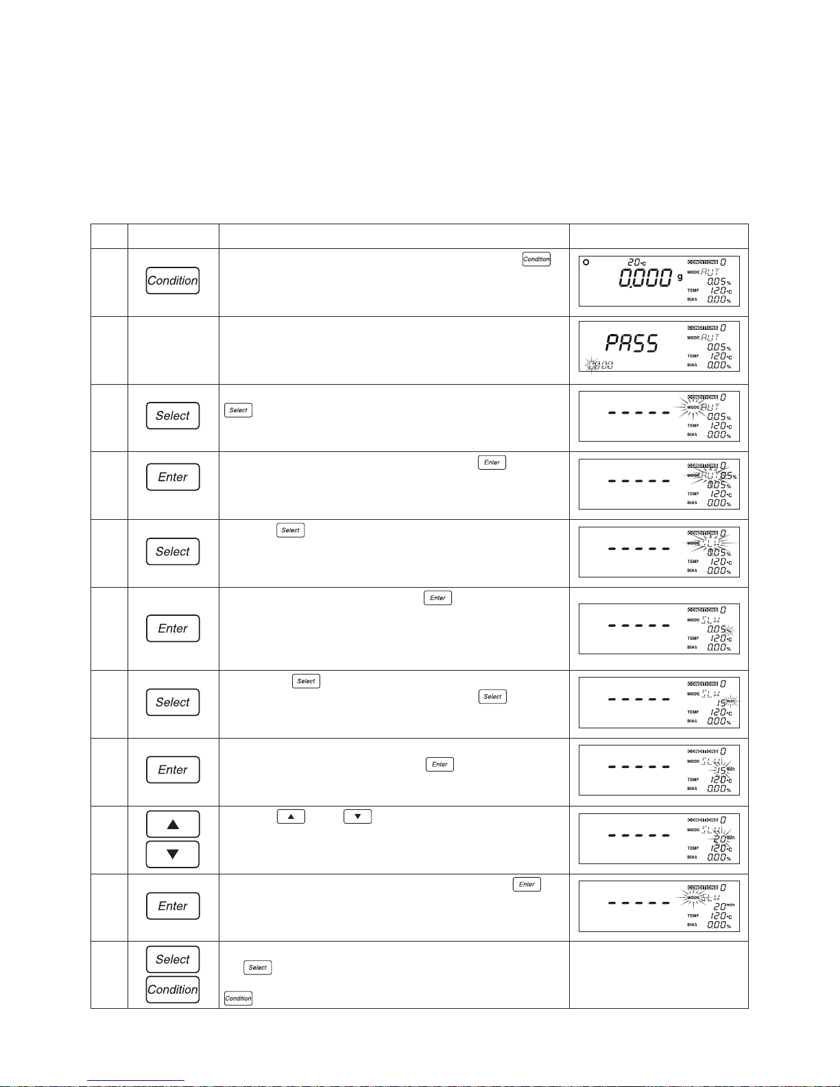
4) Specifying settings for SLOW (Low-speed drying) mode
In low-speed drying mode, the temperature is raised more gradually than when performing measurements
under normal conditions, with it taking about 5 minutes from the time when measuring begins until the
temperature reaches the specified drying temperature.
Either ‘AUTO’ (automatic halting mode) or ‘TIME’ (timed halting mode) may be specified to define the
conditions under which measuring is to be halted.
Key(s) used Operating instructions
With the display displaying the weight in grams, press the
key.
If a password has been specified, the message ‘PASS’ will be
displayed to indicate that a password should be entered. Follow
the instructions in “10-2-7 Specifying a password” on p. 46 to
enter the password.
The ‘CONDITIONS’ display area will begin to flash. Press the
key until ‘MODE’ begins to flash.
With the ‘MODE’ display area flashing, press the key. This
will cause the highlight to shift to measuring mode selection and
for the currently specified measuring mode to begin flashing.
Press the key until ‘SLW’ begins to flash.
* If ‘SLW’ is already flashing, then proceed directly on to the next
step.
When ‘SLW’ begins to flash, press the key. The highlight
will then shift to specification of low-speed drying mode settings
where the halting conditions must be specified. The units area for
timed halting mode (‘min’) or automatic halting mode (‘%’) will
begin to flash.
Pressing the
key will cause the units to switch between
minutes (‘min’) and a percentage (‘%’). Press the
key until
the desired units are displayed.
When the desired units for the halting conditions (i.e., minutes or
a percentage) begin to flash, press the
key. This will cause
the highlight to shift to the specification of the halting conditions
and the numerical field begin to flash.
Press the
key or key to select the desired halting
conditions. In this example, timed halting (20 minutes) is
specified.
When the desired time or percentage flashes, press the
key. The specified halting conditions will then change from
flashing to a constantly lit display and ‘MODE’ will begin to flash.
If you wish to specify other measuring conditions settings, press
the
key to select the setting to be specified.
To exit from specifying measuring conditions settings, press the
key instead.
Step
1
2
3
4
5
6
7
8
9
0
!
Display
Page 30
30
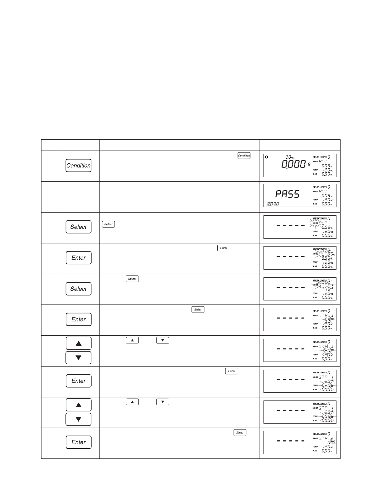
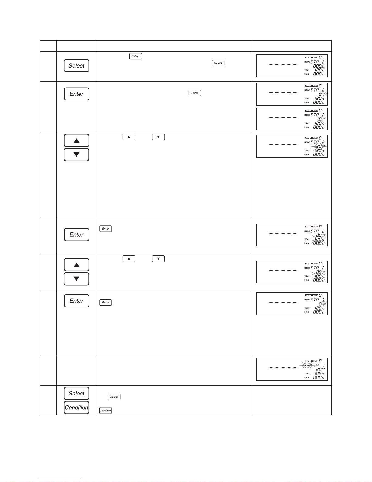
5) Specifying settings for STEP (Stepped drying) mode
In stepped drying mode it is possible to specify separate measuring conditions for up to a maximum of 5
steps. Specifying a separate drying temperature and separate measuring time for each step makes it
possible to specify finer-grained sets of measuring conditions.
In Step 1, timed halting mode must be specified as the mode used to define halting conditions. In Step 2 and
subsequent steps, it is possible to select between either automatic halting mode or timed halting mode.
* If automatic halting mode is selected as the mode to be used in Step 2 or later, that step becomes the final step.
Similarly, when timed halting mode is selected and a value of ‘0’ is specified as the measuring time, the previous
step becomes the final step.
Key(s) used Operating instructions
With the display displaying the weight in grams, press the
key.
If a password has been specified, the message ‘PASS’ will be
displayed to indicate that a password should be entered. Follow
the instructions in “10-2-7 Specifying a password” on p. 46 to
enter the password.
The ‘CONDITIONS’ display area will begin to flash. Press the
key until ‘MODE’ begins to flash.
With the ‘MODE’ display area flashing, press the key. This
will cause the highlight to shift to measuring mode selection and
for the currently specified measuring mode to begin flashing.
Press the key until ‘STP’ begins to flash.
* If ‘STP’ is already flashing, then proceed directly on to the next
step.
When ‘STP’ begins to flash, press the key. This will cause
‘STP’ to change from a flashing to a constantly lit display, for the
highlight to shift to the specification of the measuring time for Step
1, and for the measuring time to begin to flash.
Press the
key or key to select the desired measuring
time. The time may be set to a length of anywhere from 1 to 240
minutes in 1 minute increments. Note that here a time of 20
minutes has been specified.
When the desired measuring time flashes, press the
key.
The measuring time will change from a flashing to a constantly lit
display the highlight will shift to the specification of the drying
temperature, and the drying temperature will begin to flash.
Press the
key or key to select the desired drying
temperature. The temperature may be set to a temperature of
anywhere from 30 to 180°C in 1 degree increments. Note that
here a temperature of 105°C has been specified.
When the desired drying temperature flashes, press the
key. The step displayed will change from ‘STP 1’ to ‘STP 2’ and
the units area for timed halting mode (‘min’) or automatic halting
mode (‘%’) will begin to flash.
Step
1
2
3
4
5
6
7
8
9
0
Display
Page 31
31
Key(s) usedStep
!
@
#
$
%
^
&
*
Operating instructions
Pressing the key will cause the units to switch between
minutes (‘min’) and a percentage (‘%’). Press the
key until
the desired units are displayed.
When the desired units for the halting conditions (i.e., minutes or
a percentage) begin to flash, press the
key. This will cause
the highlight to shift to the specification of the halting conditions
and the numerical field begin to flash.
* Note that this step becomes the final step if automatic halting
mode (i.e., a percentage) is specified here.
Press the key or key to select the desired halting
conditions. Note that here a time of 20 minutes has been
specified. (When automatic halting has been specified as the
operation mode, the degree of change in moisture content may be
specified as anywhere from 0.01 to 0.1percent in 0.01-percent
increments.)
* Note that the previous step becomes the final step if timed halting
mode has been selected and a measuring time of ‘0’ is specified
here.
* Note that it is impossible to perform continuous measurement
(over 12 hours) in this mode. The maximum drying time for each
step is 240 minutes.
When the desired halting conditions begin to flash, press the
key. This will the display of the halting conditions to change
from a flashing to a constantly lit display, for the highlight to shift
to the specification of the drying temperature for Step 2, and for
the drying temperature to begin to flash.
Press the
key or key to select the desired drying
temperature. Note that here a temperature of 100°C has been
specified.
When the desired drying temperature is displayed, press the
key. The step displayed will change from ‘STP 2’ to ‘STP 3’
and control will shift to the specification of halting conditions. At
this point, you must go back to step ! and repeat all subsequent
steps up to this step until settings have been specified for all
steps up to the final step.
When the settings for the final step have been specified, ‘MODE’
will begin to flash.
If you wish to specify other measuring conditions settings, press
the
key to select the setting to be specified.
To exit from specifying measuring conditions settings, press the
key instead.
. . . . .
Display
Page 32
32
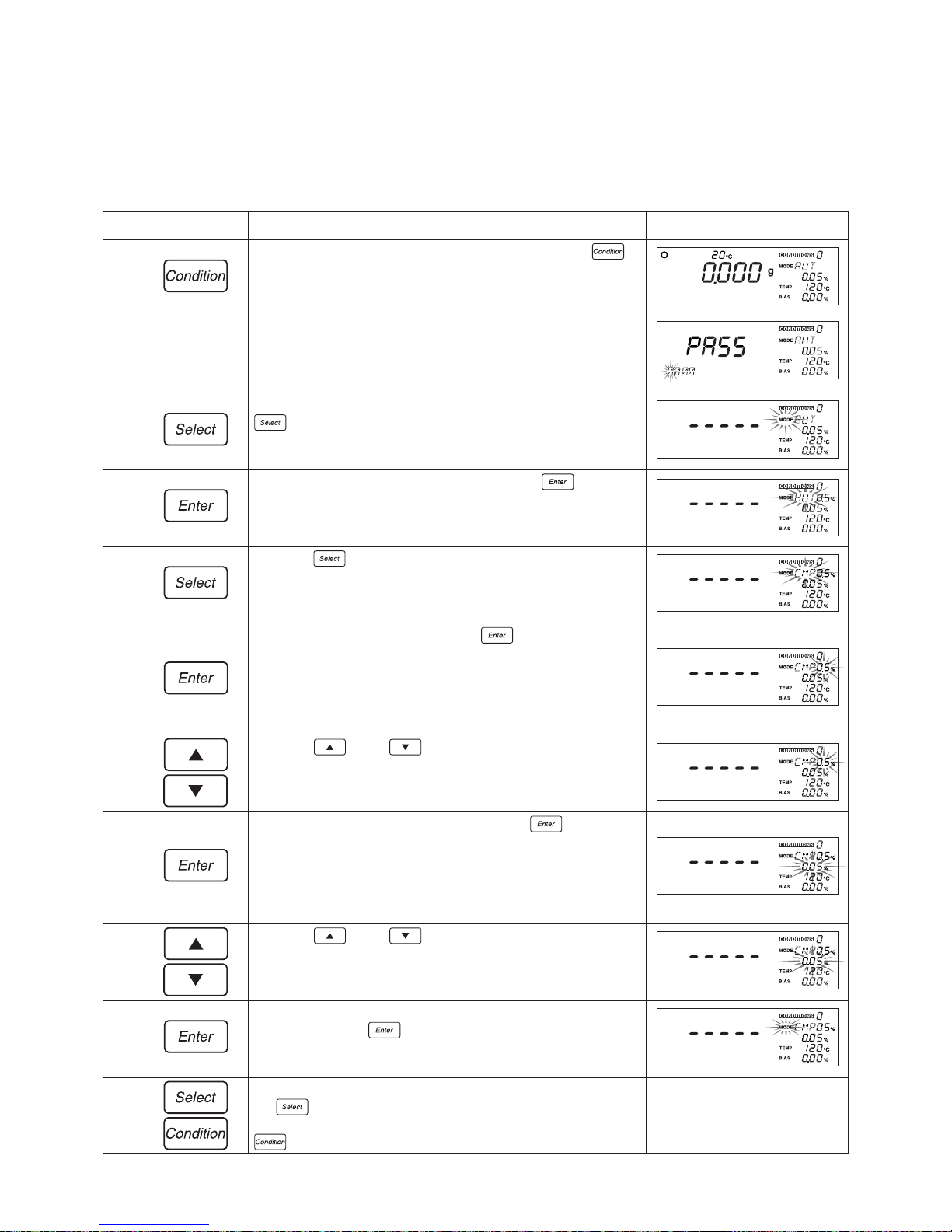
6) Specifying settings for COMPARE (Comparative measuring) mode
Comparative measuring mode is used to calculate the bias (i.e., the difference between the predicted
measurement and the measurement which would be obtained when operating in automatic halting mode)
needed when conducting predictive measurements.
When conducting predictive measurements, this mode should be used first to calculate the bias. (For further
information, see “ Comparative measuring mode” and “ Predictive measuring mode” on p. 51.)
Key(s) used Operating instructions
With the display displaying the weight in grams, press the
key.
If a password has been specified, the message ‘PASS’ will be
displayed to indicate that a password should be entered. Follow
the instructions in “10-2-7 Specifying a password” on p. 46 to
enter the password.
The ‘CONDITIONS’ display area will begin to flash. Press the
key until ‘MODE’ begins to flash.
With the ‘MODE’ display area flashing, press the key. This
will cause the display to shift to measuring mode selection and for
the currently specified measuring mode to begin flashing.
Press the key until ‘CMP’ begins to flash.
* If ‘CMP’ is already flashing, then proceed directly on to the next
step.
When ‘CMP’ begins to flash, press the key. ‘CMP’ will
change from a flashing to a constantly lit display and you will next
be required to specify the predicted value convergence range
settings (see “ Predicted value convergence range” on p. 50).
The current setting for the predicted value convergence range will
begin to flash.
Press the
key or key to specify the desired value. A
value of anywhere from 0.1 to 9.9 percent may be specified in
0.1-percent increments. Note that here a value of 0.5% has been
selected.
When the desired value is displayed, press the
key. The
flashing display of the predicted value convergence range will
change from a flashing to a constantly lit display, and the display
will shift to the automatic halting settings, and the setting
specifying the degree of change in moisture content over a 30second period will begin to flash.
Press the
key or key to select the desired automatic
halting conditions. A value of anywhere from 0.01 to 0.1 percent
may be specified in 0.01-percent increments. Note that here a
value of 0.05% has been selected.
When the desired automatic halting conditions have been
selected, press the
key. The specified setting will change
from a flashing to a constantly lit display, and ‘MODE’ will begin to
flash.
If you wish to specify other measuring conditions settings, press
the
key to select the setting to be specified.
To exit from specifying measuring conditions settings, press the
key instead.
Step
1
2
3
4
5
6
7
8
9
0
!
Display
Page 33
33
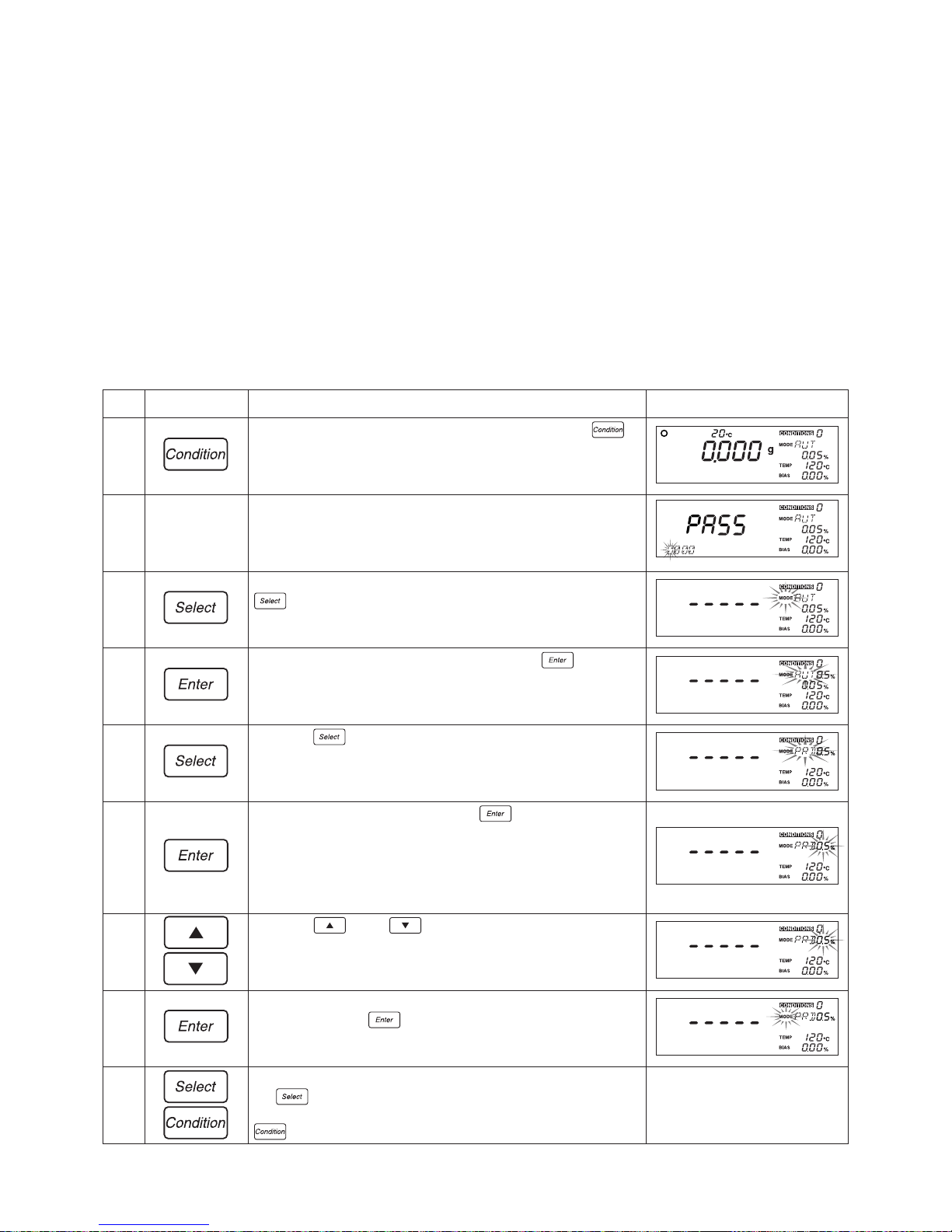
7) Specifying settings for PREDICT (Predictive measuring) mode
This mode is designed for use in reducing the amount of time required for performing measurements by
calculating a predicted final measurement from data obtained on changes in moisture content while drying is
still in progress.
Note that some materials have properties which make it difficult to obtain accurate predictions. Also note that
predictive measuring mode should to be used only after conducting measurements in comparative
measuring mode to check the precision of measurement and the possible effectiveness in terms of
shortening the measuring time.
Key(s) used Operating instructions
With the display displaying the weight in grams, press the
key.
If a password has been specified, the message ‘PASS’ will be
displayed to indicate that a password should be entered. Follow
the instructions in “10-2-7 Specifying a password” on p. 46 to
enter the password.
The ‘CONDITIONS’ display area will begin to flash. Press the
key until ‘MODE’ begins to flash.
With the ‘MODE’ display area flashing, press the key. This
will cause the highlight to shift to measuring mode selection and
for the currently specified measuring mode to begin flashing.
Press the key until ‘PRD’ begins to flash.
* If ‘PRD’ is already flashing, then proceed directly on to the next
step.
When ‘PRD’ begins to flash, press the key. ‘PRD’ will then
change from a flashing to a constantly lit display and you will next
be required to specify the predicted value convergence range
settings (see “ Predicted value convergence range” on p. 50).
The current setting for the predicted value convergence range will
begin to flash.
Press the
key or key to select the desired automatic
halting conditions. A value of anywhere from 0.1 to 9.9 percent
may be specified in 0.1-percent increments. Note that here a
value of 0.5% has been selected.
When the desired automatic halting conditions have been
selected, press the
key. The specified setting will change
from a flashing to a constantly lit display, and ‘MODE’ will begin to
flash.
If you wish to specify other measuring conditions settings, press
the
key to select the setting to be specified.
To exit from specifying measuring conditions settings, press the
key instead.
Step
1
2
3
4
5
6
7
8
9
Display
Page 34
34
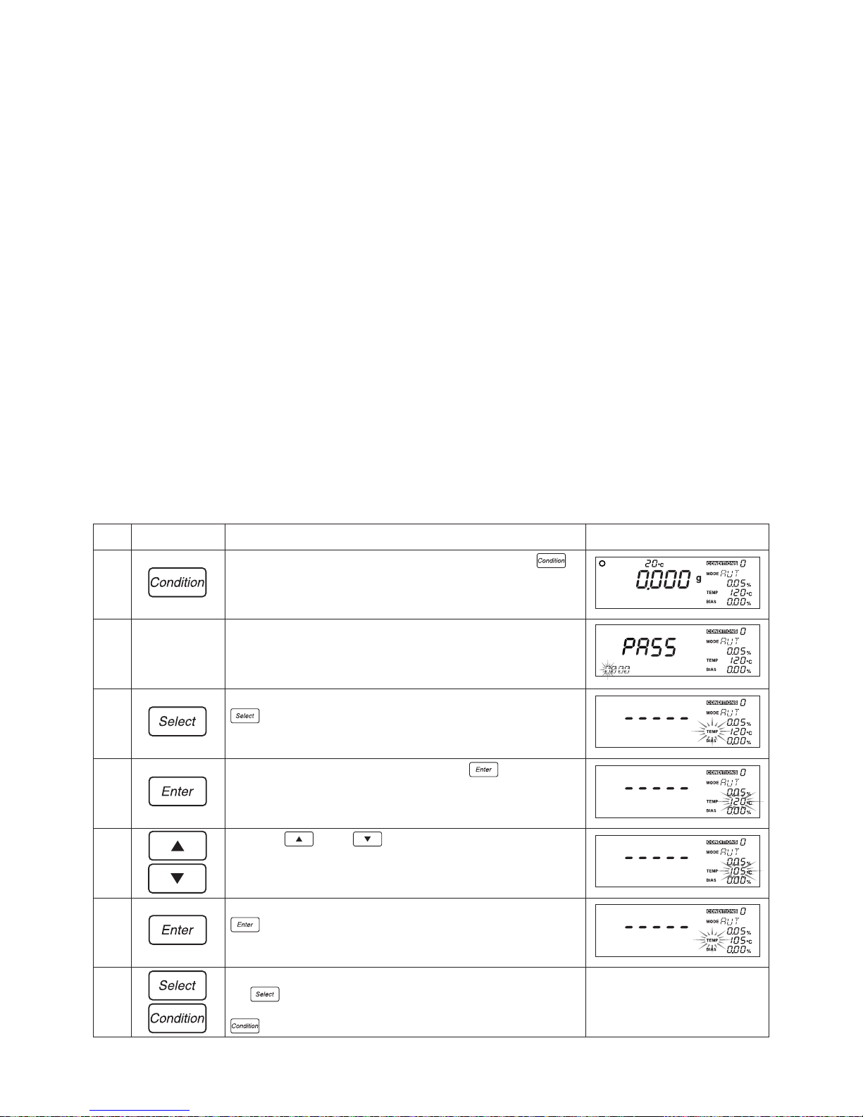
Specifying settings for the TEMP (Drying temperature)
9-2-3 TEMP (Drying temperature)
The following describes the procedure to be followed to specify the drying temperature to be used in
drying samples when conducting measurements.
While the drying temperature is set to 120°C as the default temperature at the time of shipment,
depending on the type of sample, its moisture content, or other conditions, the proper drying
temperature to use may vary. To find the proper drying temperatures to be used for different types of
materials, conduct repeated measurements until you find the correct temperature to use for each type
of material.
The temperature may be set to a temperature of anywhere from 30 to 180°C in 1-degree increments.
* Note that the drying temperature does not refer to the temperature of the material being tested but is
instead the temperature detected by the temperature sensor, and the drying temperature may differ
from the temperature of the material being dried depending on the material’s color, moisture content,
type, or shape.
* Generally speaking, drying is performed more quickly when a higher drying temperature is specified,
but if the temperature specified is too high it might result in the sample becoming burned, thus making
it impossible to obtain accurate measurements.
* Note that the meaning of the term ‘drying temperature’ as it is specified here differs from that of the
drying temperature for earlier models (e.g., the FD-600/620/100/230/240).
Key(s) used Operating instructions
With the display displaying the weight in grams, press the
key.
If a password has been specified, the message ‘PASS’ will be
displayed to indicate that a password should be entered. Follow
the instructions in “10-2-7 Specifying a password” on p. 46 to
enter the password.
The ‘CONDITIONS’ display area will begin to flash. Press the
key until ‘TEMP’ begins to flash.
With the ‘TEMP’ indicator flashing, press the key. This will
cause the highlight to shift to specification of the drying
temperature and the currently specified drying temperature to
begin to flash.
Press the
key or key to select the desired drying
temperature. Note that here a temperature of 105°C has been
specified.
When the desired drying temperature begins to flash, press the
key. The display of the specified temperature will change
from a flashing to a constantly lit display and the ‘TEMP’ indicator
will begin to flash instead.
If you wish to specify other measuring conditions settings, press
the
key to select the setting to be specified.
To exit from specifying measuring conditions settings, press the
key instead.
Step
1
2
3
4
5
6
7
Display
Page 35
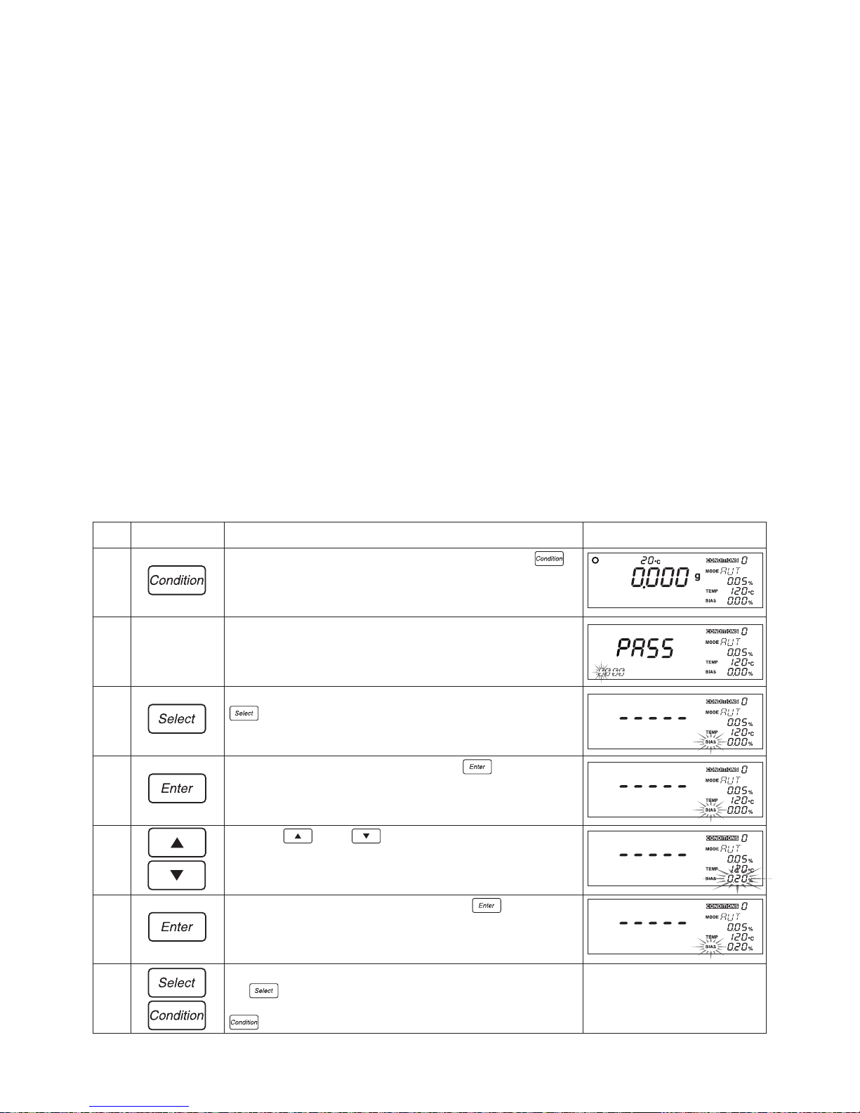
35
9-2-4 Bias
When necessary measurements should and can be corrected for bias. The bias may be specified
with a value of anywhere from -9.99 to 9.99% in 0.01% increments. A bias should be specified in
cases like those described below.
Many different conditions sometimes result in measured values (as measured using the FD-
720) failing to meet with expected (standard) values. When this happens, a bias may be set to
correlate the value as measured by the FD-720 and the expected (standard) value.
• In most cases it is possible to change the measuring conditions used to make the measurements
obtained using the FD-720 to match the expected (standard) values, but when such conditions
would cause the sample to be burned, would cause the time required for measurement to become
too long, or otherwise result in problems, a bias should be specified instead.
When using more than one unit, there may be times when it is impossible to obtain identical
measurements even when the same measuring conditions are used, because of differences in
the locations where the units are placed or because of differences in the surrounding environment. In such cases, the bias of the unit that is to serve as the standard should be set to zero
and the bias of the other units set to account for any such differences.
• For information on how to specify the bias when operating in predictive measurement mode, see
p. 52, “12-2-1 Calculating the bias to be specified when operating in predictive measurement
mode”.
Key(s) used Operating instructions
With the display displaying the weight in grams, press the
key.
If a password has been specified, the message ‘PASS’ will be
displayed to indicate that a password should be entered. Follow
the instructions in “10-2-7 Specifying a password” on p. 46 to
enter the password.
The ‘CONDITIONS’ display area will begin to flash. Press the
key until ‘BIAS’ begins to flash.
With the ‘BIAS’ indicator flashing, press the key. The
highlight will then shift to the bias specification, and the currently
specified bias value will begin to flash.
Press the key or key to select the desired bias. Note
that here a bias of 0.2% has been specified.
When the desired bias is displayed, press the key. The
display of the specified bias will change from a flashing to a
constantly lit display, and ‘BIAS’ will begin to flash instead.
If you wish to specify other measuring conditions settings, press
the
key to select the setting to be specified.
To exit from specifying measuring conditions settings, press the
key instead.
Step
1
2
3
4
5
6
7
How to set the bias
Display
Page 36
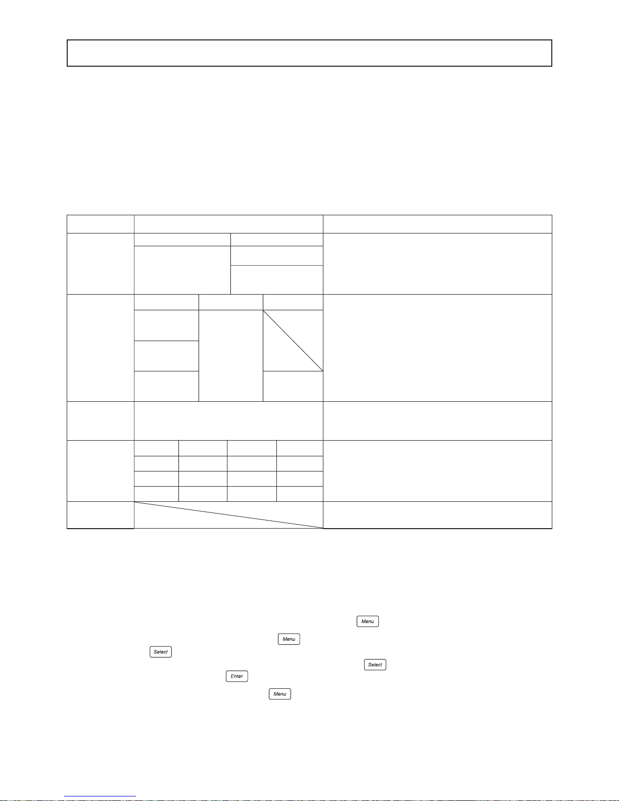
36
10. Menu Settings
Measurement standards, output data formats, and other parameters may be selected as needed.
Always be sure to specify the desired settings before performing measurements.
When changing settings, the same procedure is followed as when specifying settings for the first
time. All specified settings will be retained in internal memory, so it is not necessary to specify
settings when performing a new measurement.
10-1 Types of Menu Settings
Description
Used to select one of three possible measurement bases.
The minimum units of display for moisture content may
also be specified here. (For further information, see “10-21 Selecting units (measurement standard and minimum
display units)” on p. 37.)
Used to specify the format in which data is to be output to
a printer or computer. The user may select the destination
to which output is to be directed and the format in which
data is to be output.
When graph output (‘GRP’) has been selected, it is also
possible to specify the minimum and maximum values to
be used in the range of measurements. (For further
information, see “10-2-2 Specifying the type and format of
output” on p. 38.)
Used to specify the sample code to be output to printer or
computer. (For further information, see “10-2-3 Specifying
sample codes” on p. 41.)
Used to set the internal clock. This date and time is output
as the ‘Measurement time’ printed together with any
output data written to a printer or computer. (For further
information, see “10-2-4 Setting the date and time” on p.
42.)
Used to calibrate the internal scale. (For further
information, see “10-2-5 CAL (Scale calibration)” on p. 43.)
Menu display (Menu items)
Display 1 Display 2
MW (Wet base)
MD (Dry base)
SOL (Solid)
Display 1 Display 2 Display 3
PC
30S (30 secs.)
(Output to computer)
1M (1 min.)
TBL
(Output in
2M (2 min.)
tabular format to printer)
5M (5 min.)
GRP
(Output as
10M (10 min.) ○.○○%
graph to printer)
FIN (Final result)
○.○○%
○○○○
Display 1 Display 2 Display 3 Display 4
YMD Year Month/Day Time
MDY Month/Day Year Time
DMY Day/Month Year Time
Menu
UNIT
(Measurement
standard minimum
display unit)
OUTPUT
(Measurement
data output)
CODE
(Sample code)
DATE
(Date & time)
CAL
(Calibration)
* In addition to these settings, it is also possible to specify other settings such as the device ID (see “10-2-6
Specifying a device ID” on p. 45) or password (see “10-2-7 Specifying a password" on p. 46).
10-2 Descriptions of Individual Menu Items
Descriptions of individual menu items are given in subsection 10-2-1 and below.
1 Calling up menu settings: To call up menu settings, press the key from the weight display.
2 Selecting individual menu items: When the key is pressed, the menu item ‘UNIT’ will light up.
Pressing the key here causes the menu item lit up to change from ‘UNIT’ to ‘OUTPUT’ to ‘CODE’ to
‘DATE’ to ‘CAL’ and back to ‘UNIT’ in sequence each time the key is pressed. When the item of
interest is displayed, press the key. The settings for the selected item may then be specified.
3 Exiting from menu settings: Pressing the key when any menu item is currently lit up exits from menu
settings mode and returns to the regular weight display screen.
0.01
0.1
Page 37
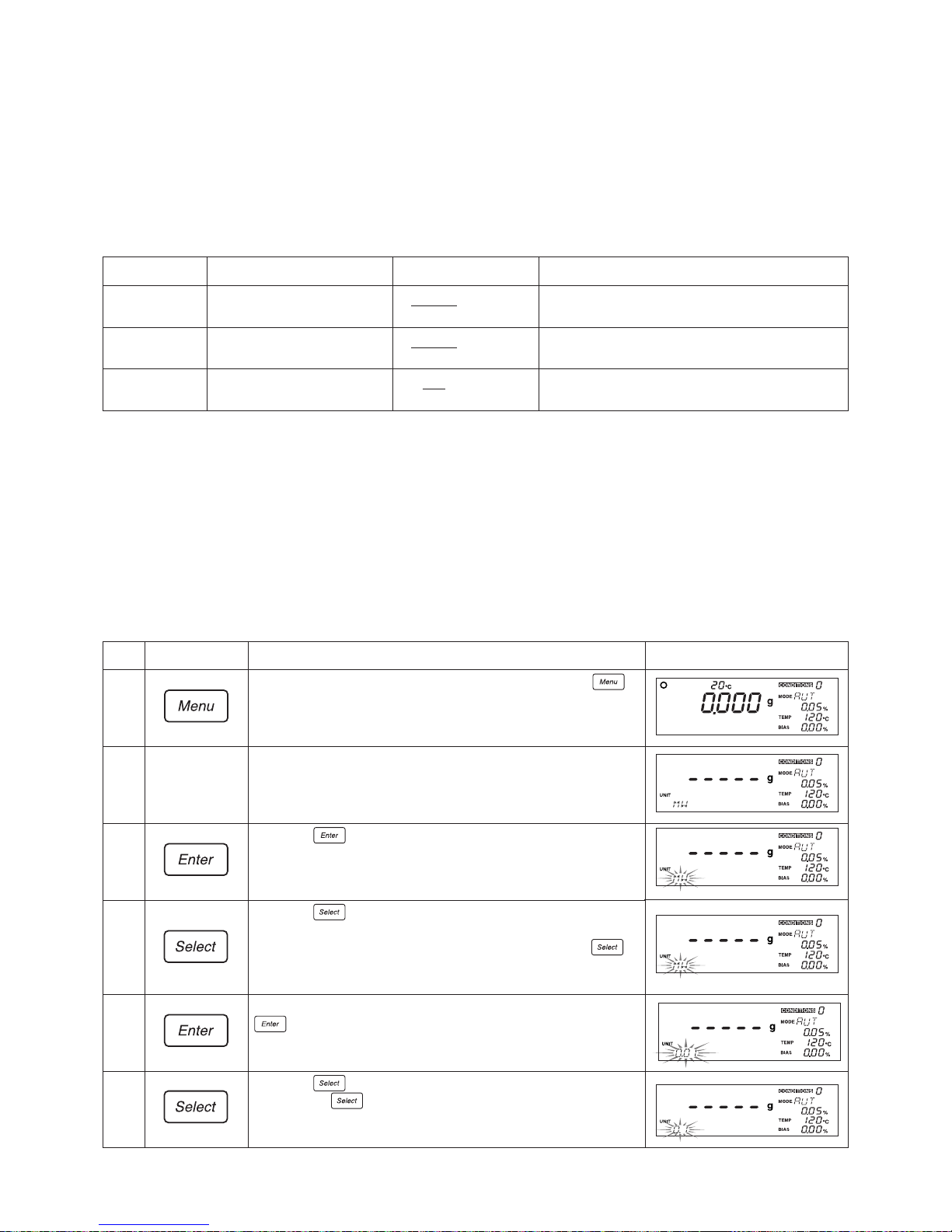
37
10-2-1 Selecting units (measurement standard and minimum display units)
1) Selecting the measurement standard
This is used to select and specify the measurement standards to be used when performing measurements. There are three different types of measurement standards: measuring by changes in
wet content, measuring by changes in dry content, and measuring by changes in solid content.
The standard selected should be chosen in accordance with the type of material being measured.
2) Selecting the minimum units of display
Select whether the least significant digit to be displayed is to be ‘0.1%’ or ‘0.01%’.
* Note that the minimum unit of display has no effect when performing comparative measurements.
How to select a measurement standard and minimum display units
Notation used in formulas:
W: Wet weight before measurement
D: Dry weight after measurement
(While a measurement is being performed, the weight at each point in time is
used as the dry weight in calculating measurements.)
Type
Wet Base
Dry Base
Solid
Description
Percentage of evaporated moisture weight with
respect to the weight before drying.
Percentage of evaporated moisture weight with
respect to the weight after drying.
Percentage of residual weight after drying with
respect to the weight before drying.
Key(s) used Operating instructions
With the display displaying the weight in grams, press the
key.
The ‘UNIT’ menu item will light up and the currently selected
measurement base will be displayed.
Press the key. This will cause the highlight to shift to
specification of ‘UNIT’ settings and for the currently selected
measurement base to begin to flash.
Press the key until the desired measurement base is
displayed. The flashing item will change from ‘MW’ to ‘MD’ to
‘SOL’ and back to ‘MW’ again in sequence each time the
key is pressed. Note that here a wet base (‘MW’) has been
selected.
When the desired measurement base begins to flash, press the
key. The currently selected minimum unit of display will
begin flashing.
Press the key to select the desired minimum unit of display.
Pressing the
key will cause the displayed units to change
from 0.01 to 0.1 and back to 0.01 again. In this example, we have
specified units of 0.1%.
Step
1
2
3
4
5
6
Formula
W – D
x 100 (%)
W
W – D
x 100 (%)
D
D
x 100 (%)
W
Menu display
MW
MD
SOL
Display
Page 38
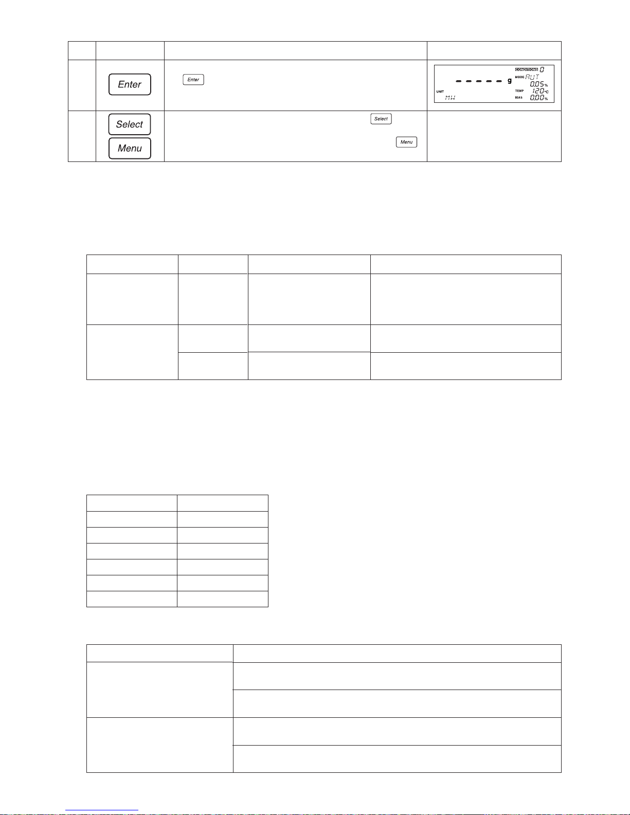
38
10-2-2 Specifying the type and format of output
The FD-720 may be connected to a separately sold printer or computer so that measurement data
can be output to the printer or computer.
1 There are three types of output formats or output destinations as shown in the table below.
Description
This is the setting which should be selected
when using the Data Logger software KDL-01
or some other software to output data through
the RS-232C interface.
This setting causes numeric output to be
printed to a separately-sold printer.
This setting causes graph output to be printed
to a separately-sold printer.
Output format
Numeric
Numeric
Graph
Menu display
PC
TBL
GRP
2 Any one of the six output intervals shown below may be selected to specify the frequency at which output is
to be generated.
The output interval specifies the amount of time which is allowed to elapse during measurement before the
next set of output is generated. When there is no need to view intermediate data from before the time when
the measurement is completed, ‘FIN’ may be selected so that only the final results are output.
* ‘FIN’ should never be selected when graph output has been selected when operating in comparative measuring
mode as that would result in no predicted measurements being output.
Output interval Menu display
Every 30 seconds 30S
Every minute 1M
Every 2 minutes 2M
Every 5 minutes 5M
Every 10 minutes 10M
Final results only FIN
3 When graph output has been selected, it is possible to specify the maximum and minimum values of the
range of values to be measured in 5-percent increments.
Range of values to be measured
Minimum: From 0 to (Maximum –5%) (Specified in 5-percent increments; may be
set to any value from 0~95%.)
Maximum: From (Minimum +5%) to 100 (Specified in 5-percent increments; may
be set to any value from 5~100%.)
Minimum: From 0 to (Maximum –5%) (Specified in 5-percent increments; may be
set to any value from 0~495%.)
Maximum: From (Minimum +5%) to 500 (Specified in 5-percent increments; may
be set to any value from 5~500%.)
Output destination
Computer
Printer
Measurement base
Wet base (%), Solid (%)
Dry base (%)
Key(s) used Operating instructions
When the desired minimum units of display begins flashing, press
the
key. The minimum unit of display will then have been
set and control will return to procedure 2.
If you wish to specify other menu settings, press the key to
select the desired menu item.
If you wish to exit from specifying menu settings, press the
key.
Step
7
8
Display
Page 39
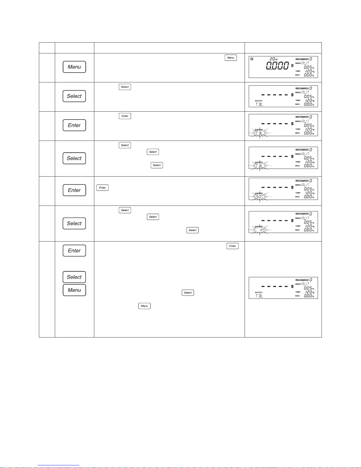
39
How to specify the output format to be used
Key(s) used Operating instructions
With the display displaying the weight in grams, press the
key.
Press the key until the ‘OUTPUT’ menu item is displayed.
Press the key. This will cause the highlight to be shifted to
the output settings and cause the currently selected output
destination to begin to flash.
Press the key until the desired output destination has been
selected. Pressing the
key here causes the menu item lit up
to change from ‘TBL’ to ‘GRP’ to ‘PC’ and back to ‘TBL’ in
sequence each time the
key is pressed. Note that here
‘TBL’ has been selected.
When the desired output destination begins flashing, press the
key. This will cause the highlight to shift to the specification
of the output interval and for the currently specified output interval
to begin to flash.
Press the
key until the desired output interval has been
selected. Pressing the
key here causes the menu item lit up
to change from ‘30S’ to ‘1M’ to ‘2M’ to ‘5M’ to ‘10M’ to ‘FIN’ and
back to ‘30S’ in sequence each time the
key is pressed.
Note that here an interval of ‘1M’ has been selected.
When the desired output interval begins to flash, press the
key. The next step to be performed here differs depending on the
output destination specified in step 4.
Procedure performed if ‘TBL’ or ‘PC’ has been selected:
The currently specified output destination will be displayed and
the display will return to the state shown in step 2. If you wish to
specify other menu settings, press the
key to select the
desired menu item. If you wish to exit from specifying menu
settings, press the
key.
Procedure performed if ‘GRP’ has been selected:
Control will shift to the specification of the range of measurement
values described in step 8 and thereafter.
Step
1
2
3
4
5
6
7
Display
Page 40
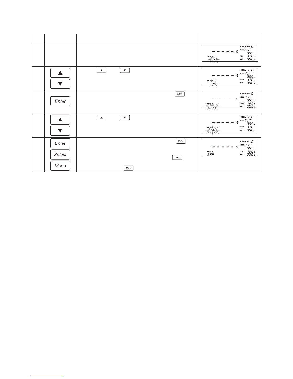
40
Specifying the range of measurement values to be used (when ‘GRP’ has been selected)
Key(s) used Operating instructions
The currently selected minimum for the range of measurement
values will begin to flash.
Press the key or key until the desired minimum is
displayed. Note that here a value of ‘5%’ has been selected.
When the desired minimum begins to flash, press the key.
The will cause the maximum for the range of measurement values
to begin to flash.
Press the key or key until the desired maximum is
displayed. Note that here a value of ‘20%’ has been selected.
When the desired maximum begins to flash, press the key.
The currently specified output destination will be displayed and
the display will return to the state shown in step 2.
If you wish to specify other menu settings, press the
key to
select the desired menu item. If you wish to exit from specifying
menu settings, press the key.
Step
8
9
0
!
@
Display
Page 41
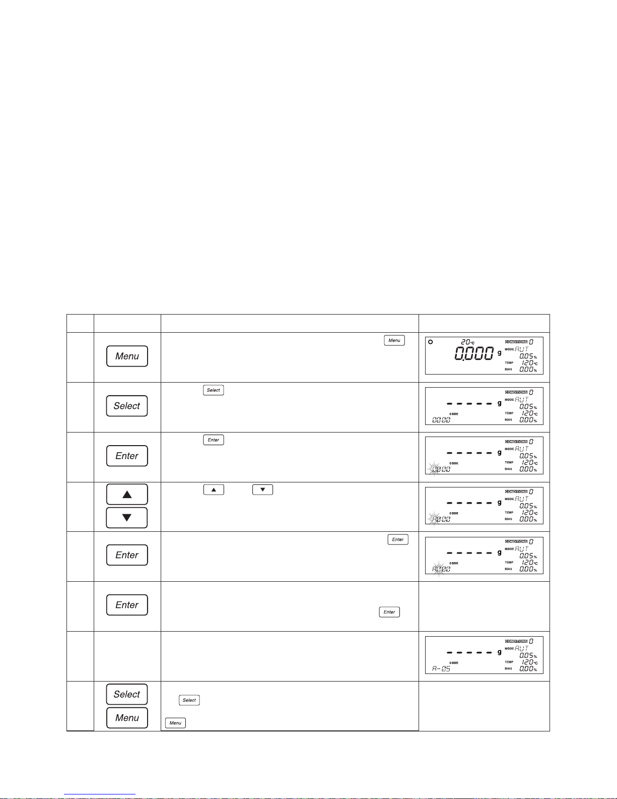
41
10-2-3 Specifying sample codes
This section describes how to specify sample codes to be used when outputting measurements to
a printer or computer. Sample codes may be specified as 4-character codes.
Any digit from 0~9, and letter from A~Z, or a hyphen (i.e., ‘—’) may be specified as the value of
the first or second character of the code.
Only digits from 0~9 may be specified as the value of the third or fourth character of the code.
* The digits in the third and fourth characters of the code are automatically incremented after each
measurement, with the value returning to ‘00’ when it would otherwise exceed a value of ‘99’.
How to specify sample codes
Key(s) used Operating instructions
With the display displaying the weight in grams, press the
key.
Press the key until the ‘CODE’ menu item is displayed.
Press the key. The highlight will then shift to the
specification of the sample code and the first character of the
currently selected ‘CODE’ will begin to flash.
Press the key or key to select a digit from ‘0’ to ‘9’, a
letter from ‘A’ to ‘Z’, or a hyphen. Note that here ‘A’ has been
selected.
When the desired character has been displayed, press the
key. The first character will then have been specified and the
second character will begin to flash.
Repeat steps 4 and 5 until the fourth character has been
specified.
When the fourth character has been specified, press the
key.
The sample code just specified will then be displayed and the
display will return to the state described in step 2.
If you wish to specify other measuring conditions settings, press
the
key to select the setting to be specified.
To exit from specifying measuring conditions settings, press the
key instead.
Step
1
2
3
4
5
6
7
8
Display
Page 42
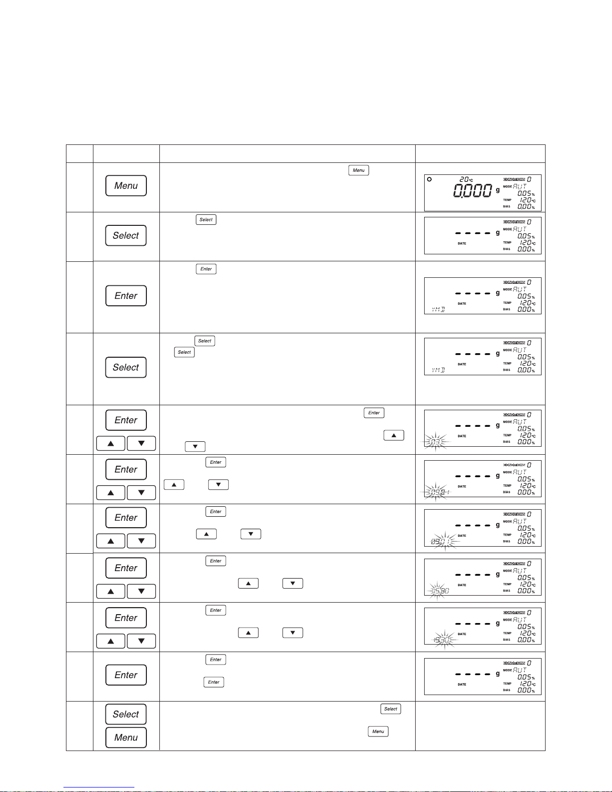
42
10-2-4 Setting the date and time
This section describes how to set the date and time. Note that while the internal clock is already
set at the time of shipment, the following procedure should be used whenever resetting the clock.
Also note that the date and time of measurement are output whenever measurement data is
output to a printer or computer.
How to set the date
Key(s) used Operating instructions
With the display displaying the weight in grams, press the key.
Press the key until the ‘DATE’ menu item is displayed.
Press the key. This will cause the highlight to shift to the output DATE
format and the currently selected output format to be displayed.
* The output format will be displayed in the order ‘YMD’ (year, month, day, and
time), ‘MDY’ (month, day, year, and time), and ‘DMY’ (day, month, year, and
time).
Press the key until the desired output format is displayed. Each time
the
key is pressed the display will change from ‘YMD’ to ‘MDY’ to
‘DMY’ and back to ‘YMD’ again.
*
Note that while we describe the procedure to be followed when specifying
dates in ‘YMD’ format, the order in which settings are specified in steps 5
through 7 differ depending on the format selected.
When the desired output format has been displayed, press the key.
This will cause the highlight to shift to the specification of the date and the 2digit value for the currently specified year to begin to flash. Press the
key or key to select the correct 2-digit year.
Pressing the
key causes the specified year to be set and the highlight
to shift to the specification of the 2-digit value for the current month. Press the
key or key to select the correct 2-digit month.
Pressing the key causes the specified month to be set and the
highlight to shift to the specification of the 2-digit value for the current day.
Press the
key or key to select the correct 2-digit day.
Pressing the key causes the specified day to be set and the highlight
to shift to the specification of the 2-digit value for the hour portion of the
current time. Press the
key or key to select the correct 2-digit
hour.
Pressing the
key causes the specified hour to be set and the highlight
to shift to the specification of the 2-digit value for the minutes portion of the
current time. Press the
key or key to select the correct 2-digit
minutes setting.
Pressing the
key causes the specified minutes selection to be set and
only ‘DATE’ to be displayed. (The clock will start counting from 0 seconds the
moment the
key is pressed.)
If you wish to specify other measuring conditions settings, press the
key to select the setting to be specified.
To exit from specifying measuring conditions settings, press the
key
instead.
Display
Step
1
2
3
4
5
6
7
8
9
0
!
Page 43
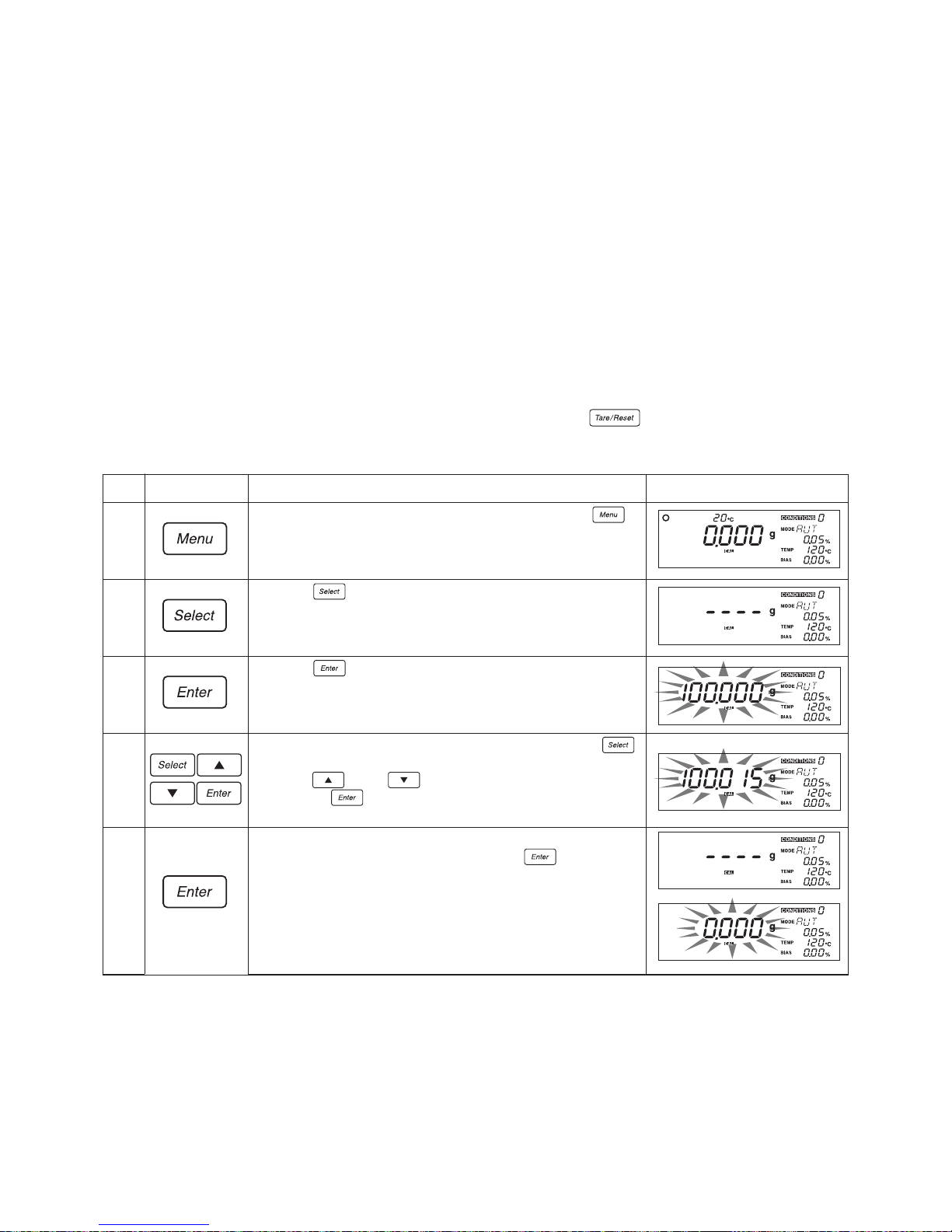
43
10-2-5 CAL (Scale calibration)
The scale is designed to allow it to be calibrated. Calibration is performed at two points: 0 and 100
grams. The FD-720 may also be connected to a printer to make it possible to automatically generate
calibration records in compliance with GLP, GMP, and ISO standards. (For further information, see
“ Printing calibration records when performing calibration” on p. 59.)
* The power to the unit should be turned on at least 30 minutes before calibration is performed in order to
ensure accurate calibration.
* The FD-720 is extremely sensitive to interference from drafts, breezes, vibration, and other disturbances
in the surrounding environment, and care should be taken to ensure that there is no such interference
before performing calibration.
* It is impossible to accurately calibrate the scale immediately after performing measurements or at any
other time when the heater lid is hot. Allow the temperature of the heater lid to cool down to ambient
temperature before performing calibration.
* The weights used should consist of standard OIML weights or some other type of non-magnetic
weights.
* When placing a weight on the sample dish, it should be placed so that the center of gravity of the weight
is near the center of the dish.
* The heater lid must be closed during calibration to prevent a calibration from being affected by drafts or
breezes, and the height of the weights used should be such that they do not come into contact with the
temperature sensor or heater.
* If you wish to abort a calibration already in progress, press the
key. An ‘Abort’ message will be
displayed and the screen will return to a weight display.
Scale calibration procedure
DisplayKey(s) used Operating instructions
With the display displaying the weight in grams, press the
key.
Press the key until the ‘CAL’ menu item is displayed.
Press the key. This will cause the calibration settings to be
displayed and the setting ‘100.000’ to begin to flash.
To change the 100-gram weight value used here, press the
key. This will cause the displayed value to stop flashing. Next,
press the
key or key to enter a value for the weight.
Pressing the
key then causes the specified weight value to
begin flashing.
Open the heater lid and place a weight of the specified weight
inside. Closing the heater lid and pressing the
key causes a
string of hyphens (i.e., ‘- - - -’) to be displayed, 100-gram
calibration to come to an end, and then a flashing value of ‘0.000’
to be displayed.
Step
1
2
3
4
5
Page 44
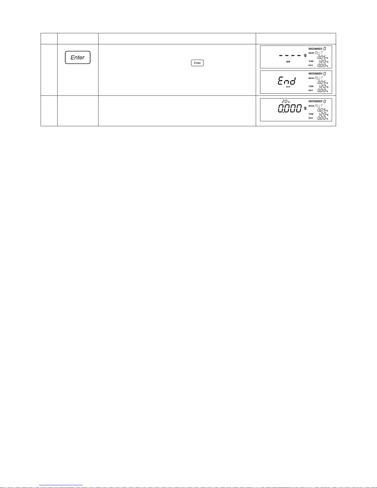
44
DisplayKey(s) used Operating instructions
With the value ‘0.000’ flashing, open the heater lid and remove
the weight.
Closing the heater lid and pressing the
key causes a string
of hyphens (i.e., ‘- - - -’) to be displayed, 0-point calibration to
come to an end, and then an ‘END’ message to be displayed.
* If the unit is connected to a printer, then a calibration record will
be automatically printed out.
After several seconds, the display will return to the regular weight
display.
Step
6
7
Page 45
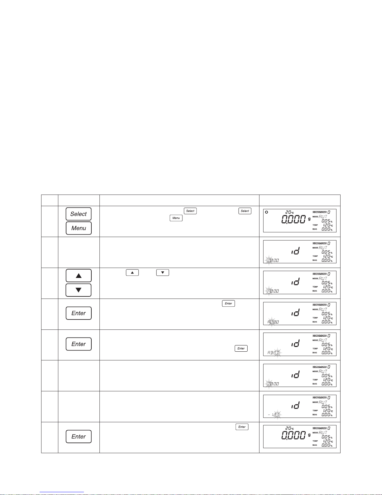
45
10-2-6 Specifying a device ID
This section describes how to specify the device ID output when outputting data to a printer or
computer. The device ID is an 8-character ID which may be set using the following characters:
digits from 0~9, letters from A~Z, and hyphens (i.e., ‘—’).
How to specify a device ID
Key(s) used Operating instructions
From the weight display, press the
key and hold the
key down while pressing the key.
The first through fourth characters of the device ID will be
displayed with the first character flashing. The indicator ‘id’ will be
displayed in the center of the display.
Press the key or key to select the desired character
(i.e., a digit from 0~9, a letter from A~Z, or a hyphen). Note that
here the letter ‘A’ has been selected.
When the desired character is displayed, press the key.
The first character will then have been specified and the second
character will begin to flash.
Repeat steps 3 and 4 until the fourth character has been
specified. Note that here a value of ‘ABCD’ has been specified.
When the fourth character has been specified, press the
key.
The fifth through eighth characters of the device ID will then be
displayed with the first of the four characters flashing.
Just as with the first four characters, repeat steps 3 and 4 until
the eighth character has been specified. Note that here a value of
‘—123’ has been specified.
When the eighth character has been specified, press the
key. This will complete the setting of the device ID, and the
display will return to the standard weight display.
Step
1
2
3
4
5
6
7
8
Display
Page 46
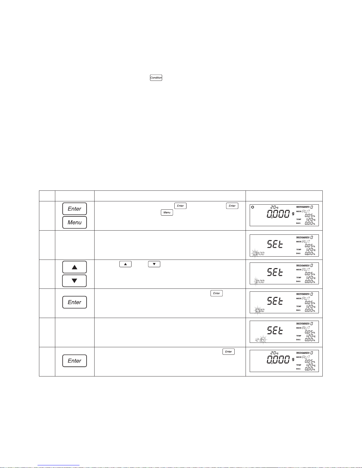
46
10-2-7 Specifying a password
In order to prevent the specified measuring conditions from being modified unexpectedly, a password may be specified to prevent other users from changing the specified conditions. The password is 4 characters in length and may be set using the following characters: digits from 0~9,
letters from A~Z, and hyphens (i.e., ‘—’).
If the password has been set to any password other than the default password of ‘0000’ set at the
time of shipment, whenever the key is pressed to specify measuring conditions the indicator
‘PASS’ is displayed in the weight display area and the user is required to enter a password.
How to specify a password
Key(s) used Operating instructions
From the weight display, press the
key and hold the
key down while pressing the key.
The default password of ‘0000’ will be displayed with the first
character of the password flashing. The indicator ‘SEt’ will be
displayed in the weight display area.
Press the key or key to select the desired character
(i.e., a digit from 0~9, a letter from A~Z, or a hyphen). Note that
here the letter ‘1’ has been selected.
When the desired character is displayed, press the key.
The first character will then have been specified and the second
character will begin to flash.
Repeat steps 3 and 4 until the fourth character has been
specified. Note that here a value of ‘1234’ has been specified.
When the fourth character has been specified, press the
key. This will complete the setting of the password, and the
display will return to the standard weight display.
Step
1
2
3
4
5
6
Display
Page 47
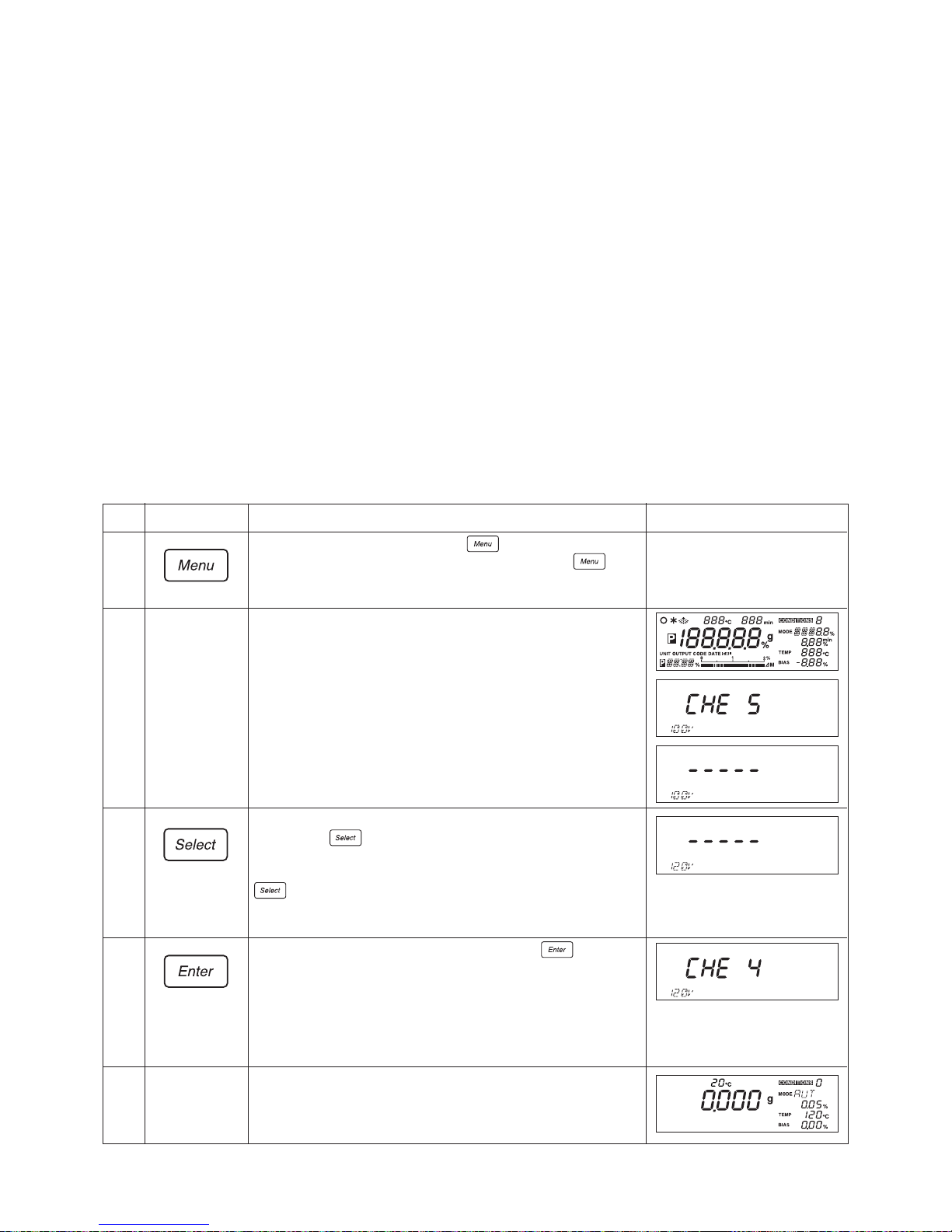
47
10-2-8 Specifying the power settings
This subsection describes the procedure to be followed in specifying the power settings to be used in
accordance with the type of power being used. Note that the voltages which may be specified differ
depending on the power setting selected using the power conversion switch. Note that this setting
must be specified when using the FD-720 in countries outside of Japan or whenever there is a
change in the type of power source being used.
Key(s) used
Turn on power
Step
1
2
3
4
5
How to specify the power settings
Operating instructions
Turn on the power while holding the
key pressed down.
* Note that you should not remove your finger from the key
until a string of hyphens (i.e., ‘- - - - -’) are displayed.
A tone will sound, the display will light up with all items lit and then
change to display first ‘CHE5’ and then a string of hyphens (i.e., ‘-
- - - -’). At the bottom left of the display will be displayed the
currently specified power settings.
If the power conversion switch has been set to ‘100~120V’, then
pressing the
key will cause the display to switch from 100V
to 110V to 120V and back to 100V in sequence. If the power
conversion switch has been set to ‘220~240V’, then pressing the
key will similarly cause the display to switch from 220V to
230V to 240V and back to 220V in sequence. Note that here a
voltage level of ‘120V’ has been specified.
When the desired voltage is displayed, press the
key. The
display will then change from ‘CHE4’ to ‘CHE0’ in sequence with
the specified voltage still displayed.
A tone will then sound and the display will return to the regular
weight display.
Display
・
・
・
・
・
Page 48
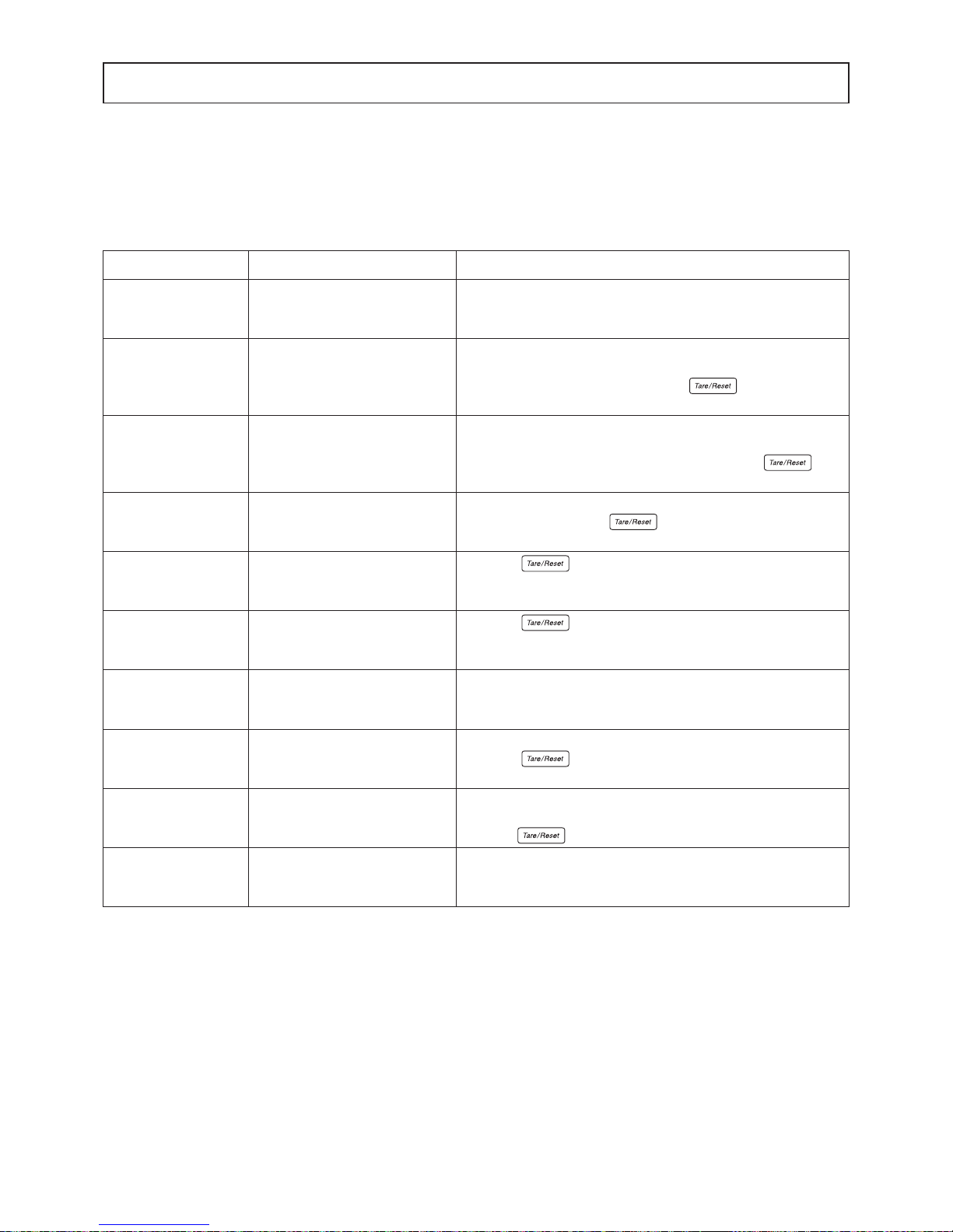
48
11. Error Messages
If any of the following error messages are displayed, follow the procedures described below to
check for the cause of the error and take appropriate action to remove the error.
If the error cannot be removed by following the procedures described below, then you should
contact the vendor from which you purchased the unit or the Kett Tokyo sales office or a local Kett
office or sales office for assistance.
Action to be taken
Remove the scale stopper located under the sample dish panel.
(See item 3 in “6. Assembly and Installation of Main Unit” on p.
14 for instructions.)
The minimum sample weight which can be used with this product
is a weight of 0.5 grams. Try measuring again using a sample of
at least 0.5 grams in weight. Press the
key to make the
error message disappear.
The maximum sample weight which can be used with this
product is a weight of 120 grams. Try measuring again using a
sample of less than 120 grams in weight. Press the
key
to make the error message disappear.
This error is displayed when a sample is added during
measurement. Press the
key to make the error message
disappear.
Press the
key to make the error message disappear.
Press the key to make the error message disappear.
Turn off the power and then turn the power back on again.
Use a calibration weight of the correct weight.
Press the
key to make the error message disappear.
Perform calibration again with the unit placed on a flat, stable surface
not subject to the effects of external vibration, drafts, or breezes.
Press the key to make the error message disappear.
Turn the power to the unit off, check to make sure that the power
conversion switch located on the back of the unit is set to the
correct position, and then turn the power back on again.
Message
ER102
ER103
ER104
ER201
ER202
ER306
ER401
ER501
ER502
ER701
Description
The scale stopper located below
the sample dish panel has not
been removed.
The sample is too light (i.e.,
under 0.5 grams).
The sample is too heavy (i.e.,
over 120 grams).
Invalid moisture content value
(Occurs when weight increases
by more than 0.1 grams)
Invalid moisture content value
(Occurs when weight being
measured is less than –1 grams)
Heater lid open
Internal weight measuring unit
communications error
Invalid weight used during scale
calibration
Instability encountered during
scale calibration
Power error
Page 49
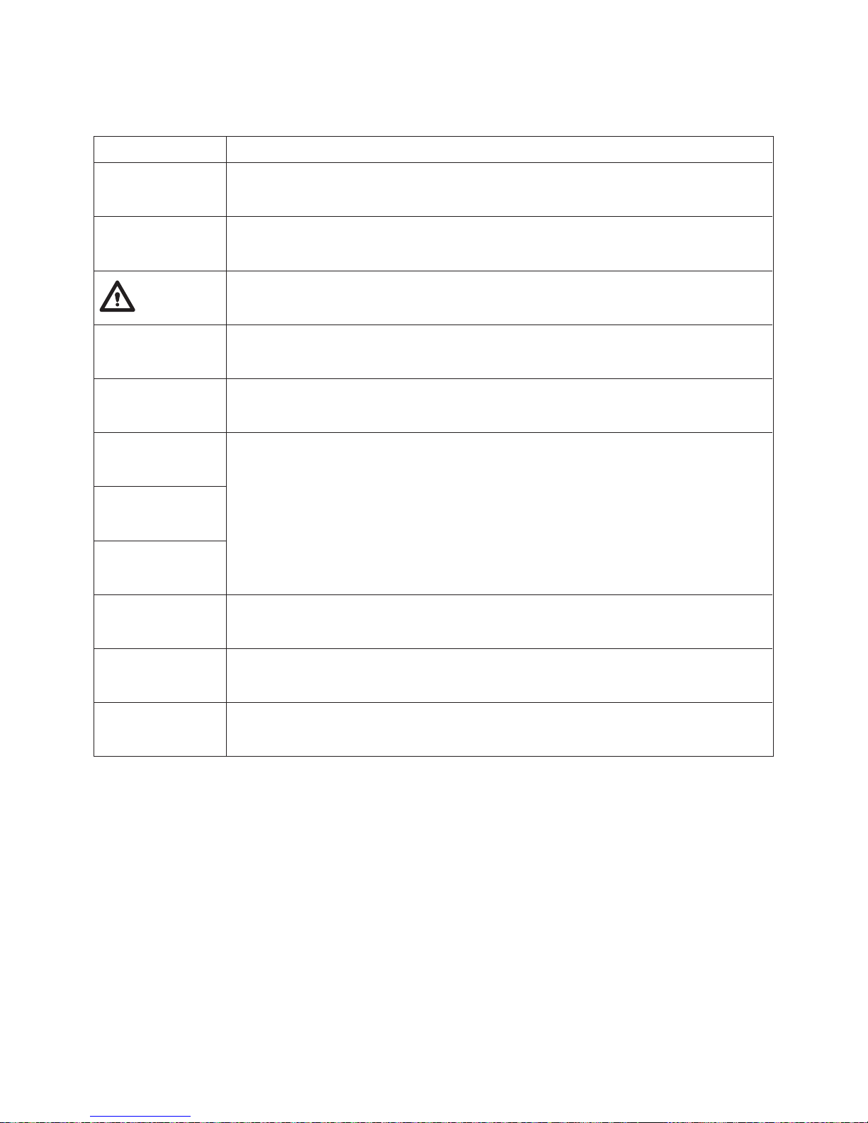
49
Message
ER301
ER302
ER303
ER304
ER305
ER601
ER602
ER603
ER702
ER801
ER802
Source of problem
Temperature sensor short-circuit
Temperature sensor not connected
Heater overheated
This error indicates the existence of an extremely hazardous condition. Turn the power off
immediately and without delay contact a Kett representative for assistance.
Temperature measurement error
Heater failure
Auto-taring mechanism error
Power failure
Memory error
Internal clock error
If any of the following errors are displayed, it indicates that a failure or breakdown of internal parts
or components has occurred. Contact the vendor from which you purchased the unit or the Kett
Tokyo sales office or a local Kett office or sales office for assistance.
Page 50

50
12. Predictive Measurements
12-1 A Description of Predictive Measuring
Infrared moisture content testers can be used to measure the moisture content of a wide range of
different materials, thus making it possible to measure the moisture content of almost anything.
This is the most important feature found in infrared testers not found in other types of testers.
At the same time, however, because an infrared moisture content tester operates by heating
samples to evaporate the moisture content, it takes a fair amount of time to obtain measurements.
In order to make it possible to shorten the amount of time required for taking measurements and
to provide a means of approximating the moisture content measurements which would be obtained using standard methods, predictive measuring mode has been developed.
In predictive measuring mode,
1 An estimate is calculated of the final moisture content while drying is still in progress.
2 It is necessary to specify three settings before measuring: the drying temperature, the pre-
dicted value convergence range, and the bias.
3 This mode is designed for use only with materials which display a drying curve of the type
generally referred to as an ‘S cur ve’.*
1
*1When compared to other curves showing the degree of drying which takes place when the mois-
ture content of a given material changes as drying progresses, an ‘S-curve’ is a curve in which the
degree of change in moisture content (i.e., ∆M) in the initial stages of drying is low and then
increases towards the middle of the drying process and then decreases progressively as the
drying process nears completion.
Drying temperature
Since the desired value is that which would be obtained when operating in automatic halting
mode, the drying temperature specified should be the same as that which would be specified in
automatic halting mode.
Predicted value convergence range
When operating in predictive operating mode, predicted values are internally calculated every 30
seconds, and while variation occurs in the calculated values, the degree of variation grows smaller
as more and more time elapses. The FD-720 has been designed to treat the final predicted value
as having been obtained when the range of variation falls within the predicted value convergence
range. The range of allowable variation in predicted final moisture content is referred to as the
predicted value convergence range.
The predicted value convergence range may be specified as a percentage anywhere from 0.1 to
9.9 percent. While specifying a higher value for the predicted value convergence range causes the
final predicted value to be calculated more quickly, the specification of a higher value may also
result in greater degrees of error occurring in predicted values. Conversely, while it is possible to
obtain more stable sets of predicted values when a lower value is specified for the predicted value
convergence range, specifying lower values tends to make it take significantly longer to calculate a
final predicted value. The value specified for the predicted value convergence range should accordingly be specified according to your objectives. Note that the default setting for the FD-720
is a value of 0.5 percent.
Page 51

51
Bias
Bias is used to change the average lower limit of fixed values with respect to predicted measurement values. On the FD-720, a bias of anywhere from –9.99 to +9.99 percent may be specified.
When performing a comparative measurement, the FD-720 automatically requests a bias to be
used to correct measurements to match those obtained in automatic halting mode.
Comparative measuring mode
In comparative measuring mode, predicted measurements are displayed while measuring is in
progress and measuring is halted under the same conditions as when operating in automatic
halting mode. The difference between the measured value and predicted value is displayed as the
bias.
In order to obtain more accurate predicted measurements, it is recommended that when calculating the bias you should perform at least 5 comparative measurements and take the average of all
measurements obtained to use as the bias.
You should also take care in terms of the amount of material and the way the sample material is
placed onto the sample dish to ensure that the sample material is laid out as evenly as possible
and sample amounts are similar.
Note that no predicted measurement or bias can be calculated if a predicted measurement is not
obtained before the measurement is completed.
Predictive measuring mode
It is possible to obtain actual predicted measurements by specifying the same drying temperature,
predicted value convergence range, and bias as calculated when performing comparative measurements in comparative measuring mode.
Note that measuring is halted if no predicted measurement has been calculated after 30 minutes
have elapsed since the time when the measurement was begun.
Page 52
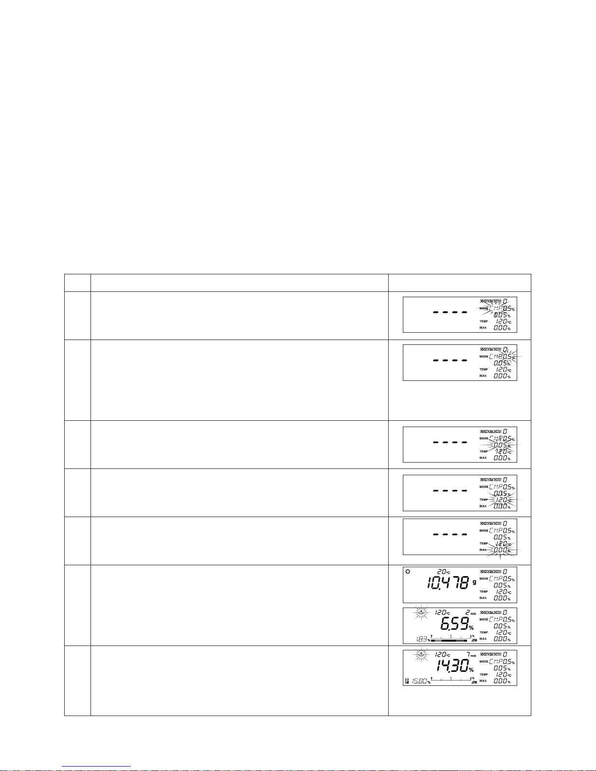
52
12-2 Procedure for Obtaining Predicted Measurements
1) Use the comparative measuring mode to calculate the bias to be specified to obtain the predicted measurement. (See
“12-2-1 Calculating the bias to be specified when operating in predictive
measurement mode”
on p. 52 for instructions on how to do so.)
2) Use the bias calculated in comparative measuring mode in step 1) to specify the bias, perform
the measurement, and evaluate the predicted measurement. (See “12-2-2 Evaluating predicted
measurements” on p. 54 for instructions on how to do so.)
3) Measure in predictive measuring mode. (See “12-2-3 Obtaining predicted measurements” on p.
55 for instructions on how to do so.)
12-2-1 Calculating the bias to be specified when operating in predictive measurement mode
Operating instructions
Set the mode to comparative measuring mode. (See 9-2-2 “6) Specifying
settings for COMPARE (Comparative measuring) mode” on p. 32 for
instructions on how to do so.)
Specify the desired predicted value convergence range. In the example shown
here, a range of 0.5% is specified.
* Note that the predicted value convergence range specified affects the amount
of time required for measurement and the accuracy of predicted measurements,
and that you should specify a range according to your objectives. (For further
information, see “ Predicted value convergence range” on p. 50.)
Specify the automatic halting conditions to be used (e.g., 0.05%).
Specify the drying temperature to be used. (For further information, see “9-2-3
TEMP (Drying temperature)” on p. 35.) In the example shown here, a
temperature of 120°C is specified.
Set the bias to 0.00%. (See “9-2-4 Bias” on p. 35 for further information.)
Place the sample onto the sample dish and begin measurement. (In the
example shown here, the initial weight is 10.478 grams.)
When the final predicted value has been calculated, it will be displayed. (In the
example shown here, the measuring time was 7 minutes and the predicted
measurement is 15.8 percent.)
Step
1
2
3
4
5
6
7
. . . . .. . . . .
Display
Page 53
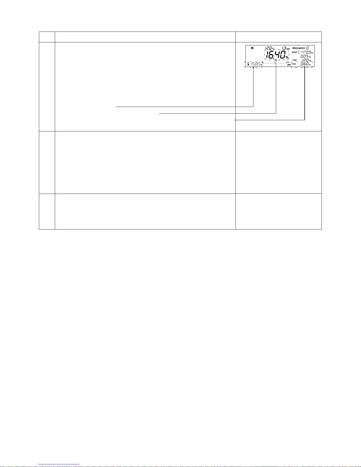
53
DisplayOperating instructions
Completion of measurement
Measuring will be completed when the conditions specified for automatic halting
mode have been met. When measuring is completed, the bias will be displayed
in the bias display area.
* If no predicted measurement is displayed even after 30 minutes has elapsed
from the time when measuring was initiated, it is probable that it is impossible
to obtain a predicted measurement.
[Measurement results]
Predicted measurement
Automatic halting mode measurement
Bias + 0.60
= 16.40 (Automatic halting mode value) – 15.80 (Predicted measurement)
Without changing any of the conditions used in steps 1 through 5, repeat
steps 6 through 8 to measure again 5 times or more and calculate the
average bias.
The average bias may then be used to specify the bias to be used in predictive
measuring mode.
* If the bias varies greatly from one time to the next when performing repeated
measurements, then it is probably safe to assume that a predicted
measurement cannot be obtained. If this happens you should measure in
automatic halting mode or in some other mode instead of predictive.
If you wish to use the calculated bias to evaluate predicted measurements,
follow the procedure described in “12-2-2 Evaluating predicted measurements”
on p. 54; if you wish to use the calculated bias to actually obtain predicted
measurements, follow the procedure described in “12-2-3 Obtaining predicted
measurements” on p. 55.
Step
8
9
0
Page 54
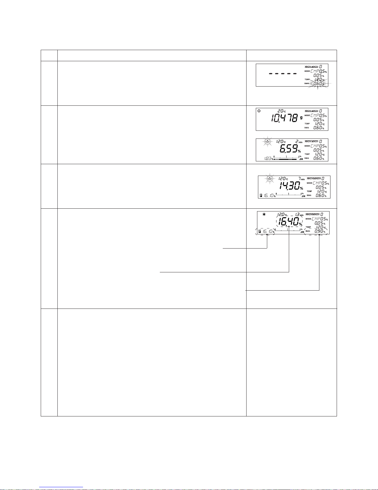
54
12-2-2 Evaluating predicted measurements
Operating instructions
With the mode set to comparative measuring mode, specify the bias calculated
following the procedure described in 12-2-1 In the example shown here, a bias
of 0.60 percent has been specified. (For information on the bias, see “9-2-4
Bias” on p. 35.)
* Do not change any other settings (i.e., the predicted value convergence range
and drying temperature) at this time.
Place the sample onto the sample dish and begin measurement. (In the
example shown here, the initial weight is 10.478 grams.)
When the final predicted measurement has been obtained, a predicted
measurement adjusted by the specified bias (here a bias of 0.60%) will be
displayed. (In the example shown here, the measuring time was 7 minutes and
the predicted measurement is 16.10 percent.)
Completion of measurement
Measuring will be completed when the conditions specified for automatic
halting mode have been met.
Measurement results
Predicted measurement corrected by the specified level of bias (0.60%)
= 15.50 (Predicted measurement when a bias of 0% is specified) + 0.60 (specified
level of bias)
Automatic halting mode measurement
Bias + 0.90
= 16.40 (Automatic halting mode value) – 15.50 (Predicted measurement when bias is
‘0‘.)
* Note that the specified bias (0.60%) does not affect the bias displayed here.
Without changing any of the specified in step 1, repeat steps 2 through 4 to
measure again 5 times or more and obtain a comparison of the values obtained
when operation in automatic halting mode and predictive measurement mode.
If the difference between the two sets of values is within an allowable range,
then the specified bias may be judged to have been an appropriate one. If the
difference between the two sets of values exceeds allowable levels, then the
average bias from the comparison just performed should be calculated, the
average then specified as the new bias setting, and the evaluation process
performed again.
* If the difference between the two sets of values exceeds allowable levels and
the bias varies sharply over repeated measurements, then it is probably safe to
assume that a predicted measurement cannot be obtained. If this happens you
should measure in automatic halting mode or in some other mode.
Step
1
2
3
4
5
. . . . .. . . .
Display
Page 55
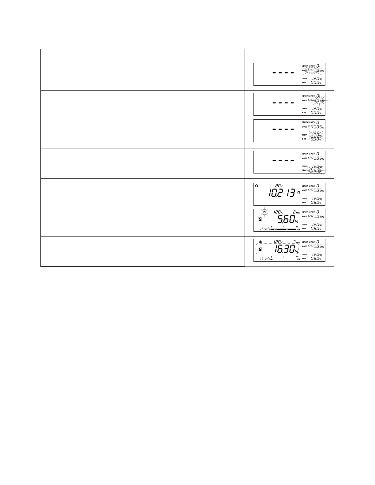
55
12-2-3 Obtaining predicted measurements
Operating instructions
Set the mode to predictive measuring mode. (9-2-2 “7) Specifying settings for
PREDICT (Predictive measuring) mode” on p. 33 for instructions.)
Specify the same settings for the predicted value convergence range and
drying temperature as those used in comparative measuring mode
(subsections 12-2-1 and 12-2-2).
Example:
Predicted value convergence range: 0.5%
Drying temperature: 120°C
Use the bias calculated following the procedures described in 12-2-1 and 12-22 to specify the bias (shown here as 0.60%). (Also see “9-2-4 Bias” on p. 35.)
Place the sample onto the sample dish and begin measurement. (In the
example shown here, the initial weight is 10.213 grams.)
Completion of measurement
The predicted measurement will then be displayed.
Step
1
2
3
4
5
. . . . .
Display
Page 56
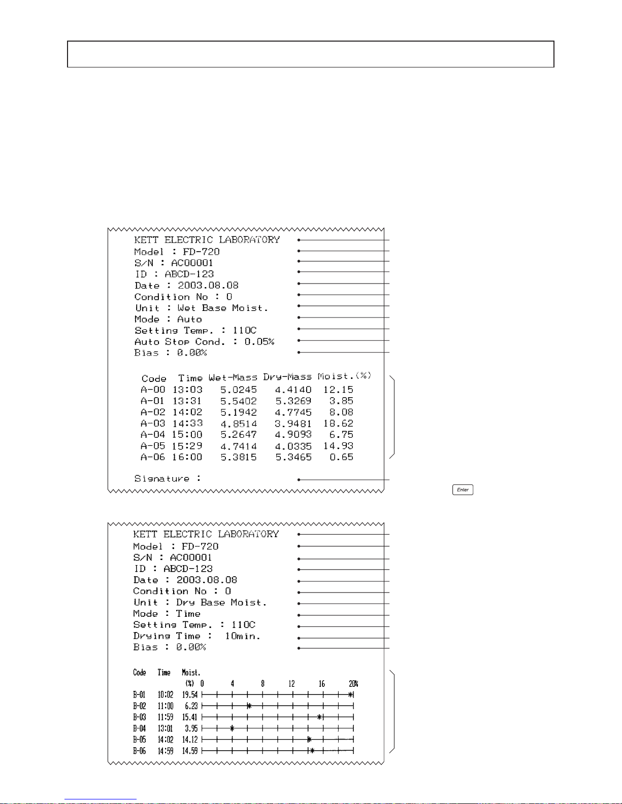
56
13. Printing Output to a Printer (Option)
The FD-720 may be connected to a printer to make it possible to output measurement data or
other information to the printer. Output which may be generated includes data consisting of intermediate or final measurements, sample codes, and measurement times.
*A dot-matrix printer may also be used, although it is impossible to obtain graphical output when using a
dot-matrix printer. Please inquire with Kett if you require further information.
13-1Sample Printer Output
Output consisting solely of final values from multiple measurements
[Tabular output (TBL)]
[Graph output (GRP)]
Supplier :
KETT ELECTRIC LABORATORY
Model : FD-720
Serial number : AC00001
Device ID : ABCD-123
Time of measurement : 2003/08/08
Measuring conditions storage area : 0
Measurement standard : Wet base
Measurement mode : Automatic halting mode
Drying temperature : 110°C
Automatic halting conditions : 0.05%
Bias : 0.00%
Sample code
Time of measurement
Pre-drying weight (g)
Post-drying weight (g)
Measured value (%)
Signature
* Pressing the
key after the
completion of measurement cause the
signature field to be printed.
Supplier :
KETT ELECTRIC LABORATORY
Model : FD-720
Serial number : AC00001
Device ID : ABCD-123
Time of measurement : 2003/08/08
Measuring conditions storage area : 0
Measurement standard : Dry base
Measurement mode : Timed halting mode
Drying temperature : 110°C
Measurement time : 10 mins.
Bias : 0.00%
Sample code
Time of measurement
Measurement graph
Page 57
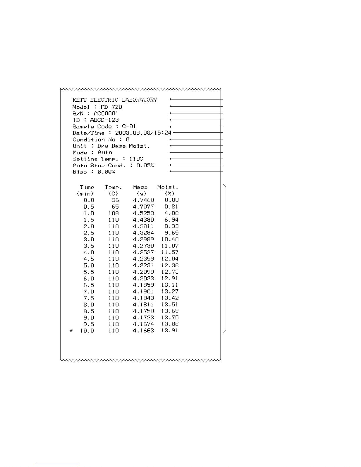
57
Output showing the intermediate values obtained during a single measurement
[Tabular output (TBL)]
* Note on the decimal precision of printed weight data
Although the minimum weight which may be displayed by the FD-720 is 0.001 grams, weights (Mass) are
printed to a precision of 4 decimal points because the values printed consist of averages from 7
measurements taken over each 30-second interval for each set of weight data output.
Supplier :
KETT ELECTRIC LABORATORY
Model : FD-720
Serial number : AC00001
Device ID : ABCD-123
Sample code : C-01
Date & time of measurement : 2003/08/08, 15:24
Measuring conditions storage area : 0
Measurement standard : Dry base
Measurement mode :
Automatic measuring mode
Drying temperature : 110°C
Automatic halting conditions : 0.05%
Bias : 0.00%
Elapsed measuring time
Changes in drying temperature
Changes in weight
Measured value (%)
Page 58
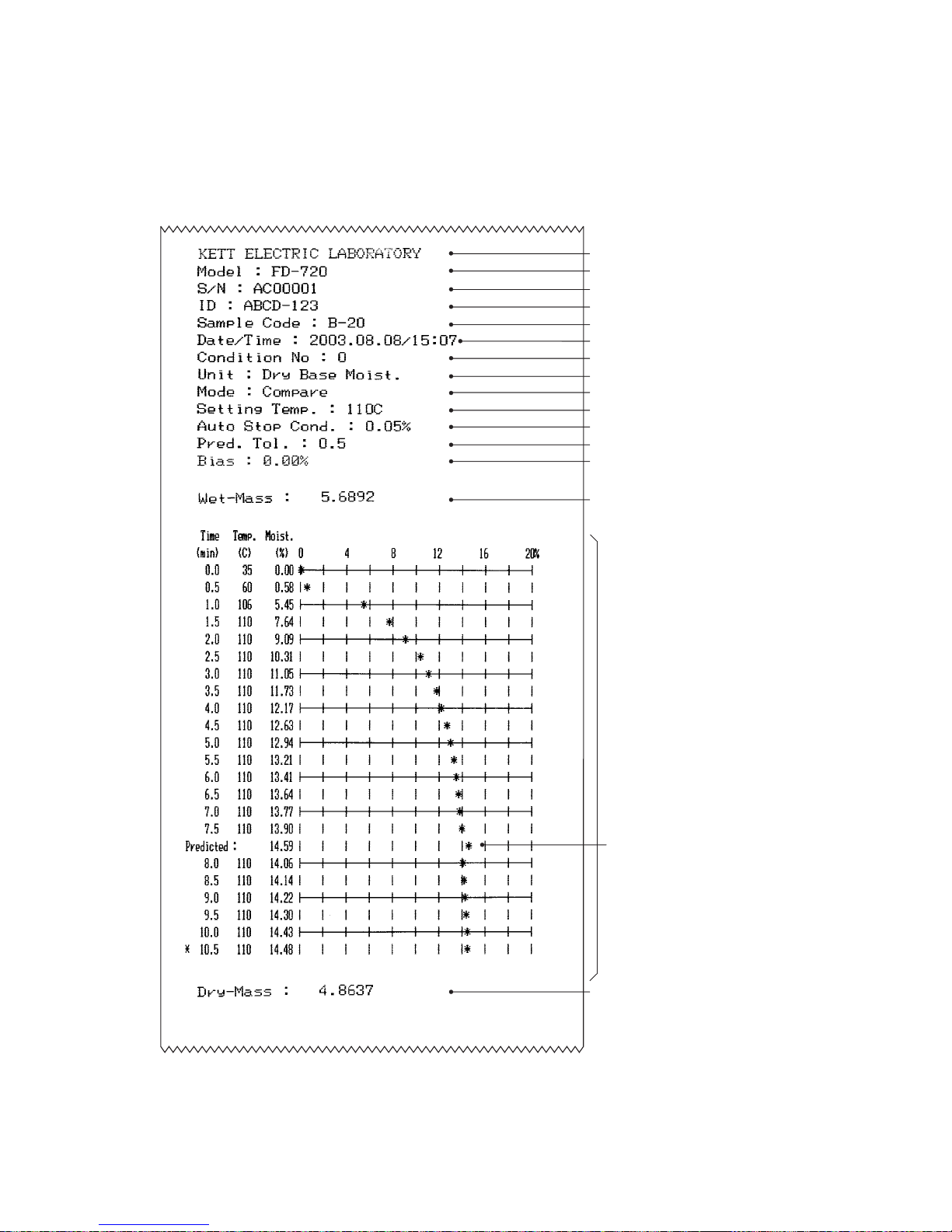
58
[Graph output (GRP)]
Supplier :
KETT ELECTRIC LABORATORY
Model : FD-720
Serial number : AC00001
Device ID : ABCD-123
Sample code : B-20
Date & time of measurement : 2003/08/08, 15:07
Measuring conditions storage area : 0
Measurement standard : Dry base
Measurement mode :
Comparative measuring mode
Drying temperature : 110°C
Automatic halting conditions : 0.05%
Predicted value convergence range : 0.5
Bias : 0.00%
Pre-drying weight : 5.6892g
Elapsed measuring time
Changes in drying temperature
Measured value (%)
Predicted measurement
Post-drying weight :4.8637g
Page 59
59
13-2 Outputting Past Measurement Data
Record are stored of up to 100 past measurements in sequence from the most recent to the
oldest. This data can be output to a printer or computer.
1 Follow the directions given on p. 38 “10-2-2 Specifying the type and format of output” to set the
output format to either ‘TBL’ or ‘PC‘.
2 From the weight display, press the key and hold the key down while pressing the
key.
3 The data will then be output (in order) beginning from the most recently measured data. To stop
printing while printing is still in progress, press the key.
Printing calibration records when performing a calibration
Supplier : KETT ELECTRIC LABORATORY
Model : FD-720
Serial number : AC00001
Device ID : ABCD-123
Time of measurement : 2003/08/08 15:18
Signature
Page 60
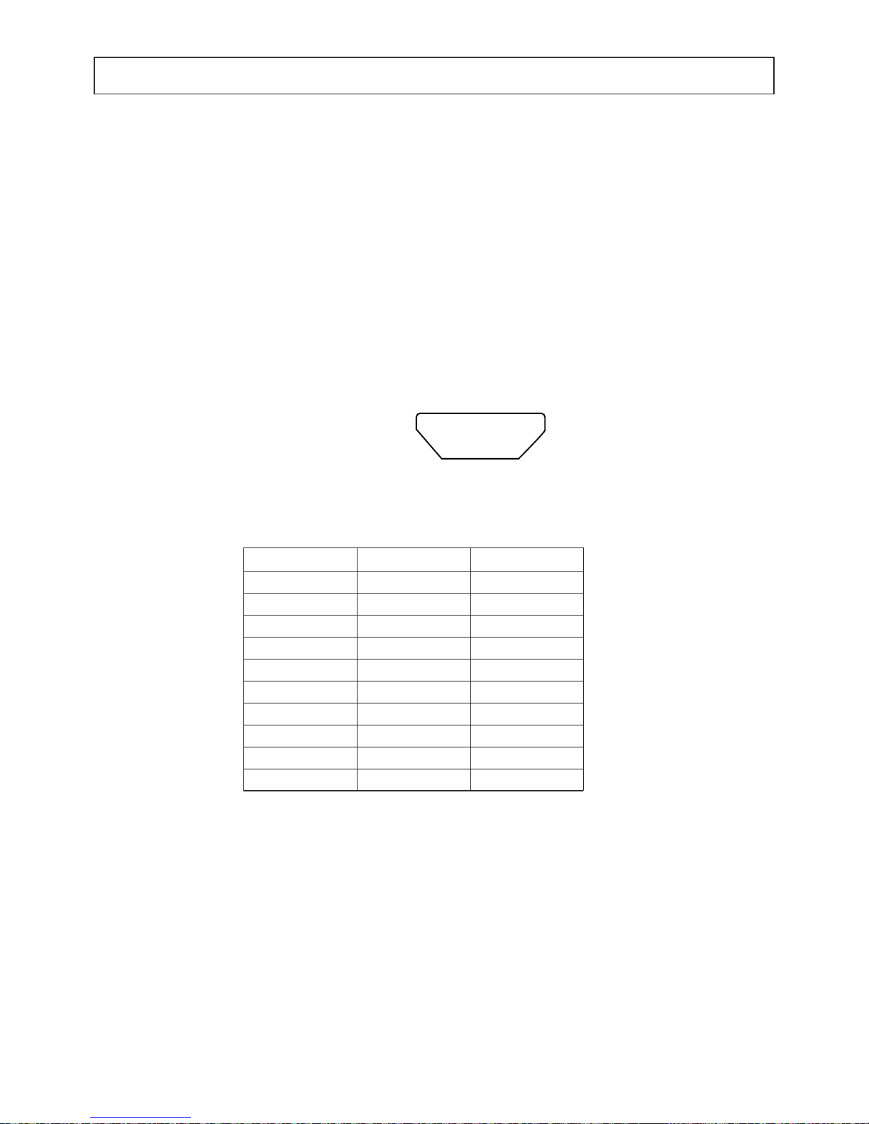
60
14. Computer Interface
The RS-232C interface may be used to connect the FD-720 to a computer with an RS-232C
interface and output measurement data to that computer.
14-1 RS-232C Interface Specifications
Interface type : RS-232C
Communications method : Asynchronous communication
Baud rate : 2400 bps
Data bits : 8 bits
Parity : None
Stop bits : 1 bit
Connector : Female D-SUB9 pins
Pin layout :
54321
9876
Pin number Direction Description
1 Not used
2 Output TXD
3 Input RXD
4 Not used
5 GND
6 Not used
7 Not used
8 Not used
9 Not used
Frame Shield
Page 61

61
14-2 Setting Up and Transmitting Data
14-2-1 Connecting the RS-232C cable
With the power to the FD-720 and the computer both turned off, connect the RS-232C cable.
Insert the connector at the end of the RS-232C cable into the RS-232C port located at the rear of
the FD-720 and then tighten the screws located at both sides of the cable connector. Follow the
same procedure to insert the RS-232C cable into the RS-232C port of the computer. If the FD-720
has been moved, check to make sure that the FD-720 is level and, if not readjust until it is level.
(See “6. Assembly and Installation of Main Unit” on p. 14 for instructions.)
14-2-2 FD-720 settings
Turn on the power to the FD-720 and set the measurement data output destination to ‘PC’. (See
“10-2-2 Specifying the type and format of output” on p. 38 for instructions.)
14-2-3 Starting up the computer
Turn on the power to the computer and, when Windows has started, start the Data Logger software KDL-01 or whatever software is to be used to read in data from the RS-232C interface.
* For instructions on how to use your computer, operating system (Microsoft Windows), or software
being used, see the user manuals provided with your computer, operating system, or software.
* The Microsoft Windows name and logo are the trademarks and registered trademarks of the Microsoft
Corporation in the United States and other countries.
Page 62

62
14-3 Computer Output Format
Interface type : RS232C
Numeric output format : JIS (ASCII)
Delimiter code : 0x09 (tab)
Delimiter : 0x0D (CR) + 0x0A(LF)
Title output format at time of start of measurement
(Underscore characters (i.e., ‘_’) are used below to indicate blanks (i.e., ‘20’ in hexadecimal)
1 “KETT_ELECTRIC_LABORATORY” + delimiter
2 “_Model_:_FD720” + delimiter
3 “_SN_:_” + “XXXXXXX” (7-byte Serial No.) + delimiter
4 “_ID_:_” + “XXXXXXXX” (8-byte ID) + delimiter
5 “_Date/Time_:_” + “XX” (2-byte year) + “.” + “XX” (2-byte month) + “.” + “XX” (2-byte day) + “/”
+ “XX” (2-byte hour) + “:” + “XX” (2-byte minutes) + delimiter
6 “_Condition_:_” + “X” (1-byte condition number) + delimiter
7 “_Unit_:_” + “Wet Base Moist.” or “Dry Base Moist.” or “Solid Content” + delimiter
8-1Automatic halting format
“_Mode_:_Auto” + delimiter
“_Setting Temp._:_” + “XXX” (3-byte temperature setting) + “C” + delimiter
“_Auto Stop Cond._:_” + “X.XX” (4-byte automatic halting conditions setting) + “%” +
delimiter
8-2Timed halting format
“_Mode_:_Time” + delimiter
“_Setting_Temp._:_” + “XXX” (3-byte temperature setting) + “C” + delimiter
“_Drying_Time_:_” + “XXX” (3-byte drying time setting) + “min.” + delimiter
8-3High-speed drying format
“_Mode_:_Rapid” + delimiter
“_Setting_Temp._:_” + “XXX” (3-byte temperature setting) + “C” + delimiter
Automatic halting: “_Auto Stop Cond._:_” + “X.XX” (4-byte automatic halting conditions
setting) + “%” + delimiter
Timed halting: “_Drying Time_:_” + “XXX” (3-byte drying time setting) + “min.” + delimiter
“_Max_Temp._:_” + “XXX” (3-byte of high-speed drying temperature) + “C” +delimiter
“_Delta M_:_” + “X.X” (3-byte of degree of high-speed drying maintenace condition) +
delimiter
8-4Low-speed drying format
“_Mode_:_Slow” + delimiter
“_Setting Temp._:_” + “XXX” (3-byte temperature setting) + “C” + delimiter
Automatic halting: “_Auto Stop Cond._:_” + “X.XX” (4-byte automatic halting conditions
setting) + “%” + delimiter
Timed halting: “_Drying Time_:_” + “XXX” (3-byte drying time setting) + “min.” + delimiter
Page 63

63
8-5Stepped mode format
“_Mode_:_Step” + delimiter
tab + “Temp (C)” + tab + “Time (min.)” + delimiter
The following output then appears the same number of times as the number of specified
steps:
“_Step” + “X” (1-byte step number) + tab + “XXX” (3-byte temperature setting) + tab +
“XXX” (3-byte drying time setting) + delimiter
8-6Comparative mode format
“_Mode_:_Compare” + delimiter
“_Setting Temp._:_” + “XXX” (3-byte temperature setting) + “C” + delimiter
“_Auto Stop Cond._:_” + “X.XX” (4-byte automatic halting conditions setting) + “%” +
delimiter
“_Pred. Tol._:_” + “X.X” (Predicted value convergence range) + delimiter
8-7Predictive mode format
“_Mode_:_Predict” + delimiter
”_Setting Temp._:_” + “XXX” (3-byte temperature setting) + “C” + delimiter
“_Pred. Tol._:_” + “X.X” (Predicted value convergence range) + delimiter
9 “_Bias_:_” (+“-”) + “X.XX” + “%” + delimiter
Measurement output format
tab + “Time (min.)” + tab + “Temp. (C)” + tab + “Mass (g)” + tab + “Moist (%)” + delimiter
Intermediate measurement output format
tab + “XXX.X” (5-byte measuring time) + tab + “XXX” (3-byte of thermistor temperature) + tab +
“XXX.XXXX” (8-byte sample weight) + tab + Moisture content “XXX.XX” (6-byte moisture content)
+ delimiter
Final measurement output format
“*” + tab + “XXX.X” (5-byte measuring time) + tab + “XXX” (3-byte of thermistor temperature) + tab
+ “XXX.XXXX” (8-byte sample weight) + tab + Moisture content “XXX.XX” (6-byte moisture content) + delimiter
Sample output
Maker
Model
Serial number
Device ID
Sample code
Date & time of measurement
Measuring conditions storage area
Measurement standard
Measurement mode
Drying temperature
Automatic halting conditions
Bias
Elapsed measuring time
Changes in drying temperature
Changes in weight
Measured value (%)
Page 64
64
15. Maintenance
15-1 Performing Maintenance
Always be sure to remove the plug from its socket before performing maintenance.
1 Removing parts and components
Remove the sample dish first, followed by the sample dish handler, sample dish tray, and wind
shield in order.
2 Installing parts and components
See “6. Assembly and Installation of Main Unit” on p. 14 for instructions on how to install parts and
components.
3 Remove any traces of spillage or soiling from samples.
4 Maintenance of the main unit
Use a soft, dry cloth to wipe away any dirt or soil.
Avoid applying strong pressure when wiping, even if you find dirt or soiling difficult to remove.
If you find it particularly difficult to remove dirt or soiling, wet a cloth in water, or in water with a
small amount of neutral detergent, wring the cloth thoroughly, and wipe. Next, rinse the cloth in
water and wring it out to remove any detergent, and wipe again, then allow to dry.
5 Maintenance of parts and accessories
Remove the spoon, spatula, sample dish, and wind shield from the main unit, and wash in
water with a soft sponge.
Reattach to the main unit and wait until completely dry before using the unit again.
* When using detergents, be sure to follow the instructions provided with the detergent in
question.
* Never use paint thinner, benzene, or any volatile cleaning agents, or any abrasive cleansers or
polishes.
* Never use wire brushes or other hard cleaning tools.
Warning
Caution
Page 65

65
15-2 Replacing Fuses
1 Remove the power cord from the unit.
2 The fuse holder is located at the rear of the unit.
Insert a slot screwdriver or similar tool from the top
of the fuse holder, and pull the fuse holder
towards your body.
3 Remove the fuses from the fuse holder and check
to see if any are burned out.
4 If there are no burned-out fuses, return the fuse
holder to its original position. If there is a burnedout fuse, replace it with one of the spare fuses or
with a compatible (T8A 250V) fuse.
5 Return the fuse holder to its original position in the
main unit.
6 Insert the power cord back into the main unit.
* If a fuse blows out again after being replaced,
then there may be a problem with your unit,
and you should have it checked and/or
repaired.
Page 66

Page 67

Page 68
0706•PA•0201•200
 Loading...