


D3
Instlltion Guide
Models
D3-FXRD
D3-ADRD
D3-WWRD
D3-FXSQ
D3-ADSQ
D3-WWSQ

!
WARNING
Shock Hzrd. May result in serious injury or deth.
Turn power OFF at circuit breker or remove fuse. Dmge to this
product cused by wiring with power on voids the wrrnty.
Due to the risk of electric shock, a licensed electricin should instll
this power supply unit in strict complince with the Ntional Electricl
Code nd ny stte or locl code which my pply.
2|D3 INSTALLATION GUIDE
© 2019 Ketra, Inc. All rights reserved
P/N 040444 Rev E

Contents
Product Overview 4
Included Components/Supported Models 5
Included Components 5
Supported Models 5
Specifictions 6
Instlltion 7
Part 1: Mount the D3 7
Prt 2: Wire the Fixture 12
Prt 3: Instlling Drywall 13
Part 4: Apply Spckle Flnge Trim Retiner (Mud-In Only) 13
Prt 5: Apply Joint Compound 14
Prt 6: Apply Trim 14
Additionl Opertions 16
Troubleshooting 18
Wrrnty Tech Support 19
3|D3 INSTALLATION GUIDE
© 2019 Ketra, Inc. All rights reserved
P/N 040444 Rev E

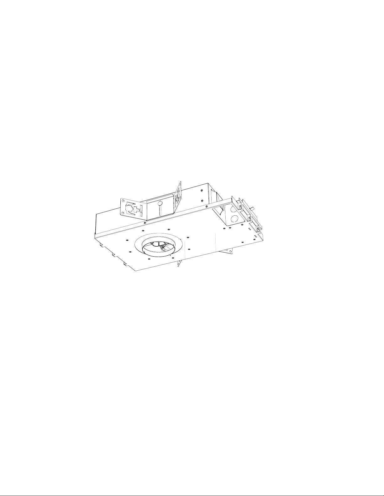
Product Overview
Ketr’s D3 family includes fixed, djustable, nd wll-wsh downlights. Every model
fetures a low-profile housing, wireless communiction, and field-replceble optics
nd electronics. With a welth of trim and optic accessories, the D3 is ideal for a large
variety of applications. It uses a fully-tunable spectrum capable of delivering high-
quality white, saturated, and pastel light.
butterfly bracket
hanger bar slot
IC rated/ airtight enclosure
aperture rotation
power supply
AC input wiring
junction box
height adjust
tilt lock
primary optic
(field replaceable)
finish trim
(field replaceable)
butterfly bracket
IC rated/ airtight enclosure
rotation indication
(square housing only)
rotation lock
4|D3 INSTALLATION GUIDE
© 2019 Ketra, Inc. All rights reserved
P/N 040444 Rev E

Included Components/Supported Models
Included Components
( 2 ) Butterfly Brackets
Housing with Emitter Optic
(Models as specified)
( 2 ) Nailer Bars
Trim (Model as specified)
Supported Models
D3-FXRD
D3-ADRD
D3-WWRD
D3-FXSQ
D3-ADSQ
D3-WWSQ
For instructions on setting default states in Design Studio, see the Design Studio Manual available on our website. The manual has
sections dedicated to emergency mode and setting default states for Ketra lights
5|D3 INSTALLATION GUIDE
© 2019 Ketra, Inc. All rights reserved
P/N 040444 Rev E

INSTALLATION
Specifictions
Optical Performance
Delivered Lumen Output
Beam Angle
(1 in/ 25.4 mm recess)
15° beam low glare 650 lm 882 lm 1092 lm
25° beam, low glare 623 lm 845 lm 1046 lm
40° beam, low glare 569 lm 772 lm 955 lm
60° beam, low glare 561 lm 760 lm 941 lm
15° beam high output 682 lm 928lm 1148 lm
25° beam, high output 678 lm 923 lm 1142 lm
40° beam, high output 646 lm 878 lm 1087 lm
60° beam, high output 630 lm 857 lm 1061 lm
CRI (Ra)3 >90 (R9>90) 2400K5000K TYP
Lumen Maintenance 50,000 hours to L70 @ 25 ˚C T
Color Spatial Uniformity <2 MacAdam ellipses across
Color Point Range 1400 ˚K10,000 ˚K, Fully
Equivalent Traditional Lamp 75 W halogen
Dimming Range 0.1100% lm
Power Consumption D3.13 13 W
Voltage*
Power Factor >0.9
Current 150 mA Max
Delivered Ecacy
Beam Angle
(1 in/ 25.4 mm recess)
15° beam low glare 72 lm/W 68 lm/W 61 lm/W
25° beam, low glare 69 lm/W 65 lm/W 58 lm/W
40° beam, low glare 63 lm/W 59 lm/W 53 lm/W
60° beam, low glare 62 lm/W 58 lm/W 52 lm/W
15° beam high output 76 lm/W 71 lm/W 63 lm/W
25° beam, high output 75 lm/W 71 lm/W 62 lm/W
40° beam, high output 72 lm/W 68 lm/W 59 lm/W
60° beam, high output 70 lm/W 66 lm/W 58 lm/W
9W 13W 18W
field angle
Saturated, Pastel
D3.18 18 W
120 V 60 Hz
220277 V 60 Hz
220277 V 50 Hz
9W 13W 18W
Environmental
Operating Temperature 040 °C
Storage Temperature -2080 °C
Humidity 095%, Non-condensing
Certification UL, cUL, RoHS, FCC Class B
Location UL Damp Location, UL Wet
Location Available with Lens Trim
Electrical
Mounting Options Hanger Bars / Butterfly Brackets
Field Replaceable Optics Yes
Field Replaceable
A
Light Engine
Field Replaceable
Power Supply
Additional Optic Lens Holder 2.5 in/63.5 mm Lens, ⁄ in/3.175 mm Thick
Additional Trim Lens Holder 2.75 in/69.85 mm Lens, ⁄ in/3.175 mm Thick
Housing Material Powder Coated Steel, Polymer
Lens Material Glass
Yes
Yes
Dimensions
Ceiling Hole Diameter 4 in/ 101.6 mm Flanged,
5.5 in/ 139.7 mm Mud-in
Trim Outside Diameter 4.62 in/ 117.348 mm
Trim Inside Diameter 3.75 in/ 95.25 mm
Trim Thickness ⁄ in/ 1.5875 mm
Optics Outside Diameter 2.5 in/ 63.5 mm
Trim Depth 1 in/ 25.4 mm
Ceiling Thickness 0.625 in–1.5 in/ 15.87538.1 mm
Emitter Vertical Adjustment
(tool-free)
Housing Vertical Adjustment
via Butterfly Bracket
Housing Height 3.50 in/ 88.9 mm
Housing Length 18.38 in/ 466.852 mm
Housing Width 10.07 in/ 255.778 mm
0.75 in/ 19.05 mm
1.75 in/ 44.45mm
Surge Protection 2.5 KV
Control Protocol KetraNet Mesh
* Ketra lighting products should not be connected to, or directly controlled by, AC mains line voltage dimmers. These types of dimmers may
also be referred to as phase cut, triac, forward-phase, reverse-phase, ELV, or MLV dimmers. Ketra's lighting products should only be controlled
via our digital control architecture. Ketra does not recommend switching power on/o to Ketra lighting products via relays, contactors, or
manual toggle switches. When the lighting products are disconnected from power they cannot respond to digital commands from control
devices. This could confuse end users as the lighting may be in a state that is inconsistent with the control devices. Please refer to our controls
products installation guides for more information.
6|D3 INSTALLATION GUIDE
© 2019 Ketra, Inc. All rights reserved
P/N 040444 Rev E

INSTALLATION
Instlltion
All touch-points inside the D3 housing are colored red.
All customer-accessible screws are Phillips.
Part 1: Mount the D3
Mounting can be done with either nailer bars or butterfly brackets.
Option 1
Nailer Bars
• Allow horizontal movement
post-mounting
• Ideal with wooden studs or
t-grid ceilings
Option 2
Butterfly Brackets
• Allows horizontal or vertical movement
post-mounting
• Ideal for commercial settings
continued on next page
7|D3 INSTALLATION GUIDE
© 2019 Ketra, Inc. All rights reserved
P/N 040444 Rev E

INSTALLATION
Option 1
MOUNTING WITH NAILER BARS
1. Attach nailer bars
a. If ceiling thickness is 0.75 in (19.05 mm) or greater: Use pliers to break o the tabs at the end
ofboth nailer bars. (see fig. 1)
b. Insert the inner nailer bar into the three housing clasps on the end of the D3 housing. Make sure
the screw is on top. (see fig. 2)
c. IInsert the outer nailer bar into the same housing clasps, locking the inner and outer halves
together. Make sure the screw is on top. (see fig. 3)
d. Repeat steps a-b for the clasps on the other end of the housing
fig. 1 (optional) fig. 2
fig. 3
2. Mount downlight in the ceiling
Note: For optimal radio communication, ensure that the radio dome is not above or adjacent to
anything metallic.
a. Use a level to ensure the nailer bars are parallel to the ground.
Note: The D3’s collar needs to be flush to the ceiling plane or 0.0625 in (1.5875 mm) above it.
b. Screw the ends of both bars into the wooden joists, fixing the housing in place. (see fig. 3)
c. T- Grid ceiling only: Bend the tabs on the nailer bars to lock them to the t-grid. (see fig. 4)
fig. 4
8|D3 INSTALLATION GUIDE
© 2019 Ketra, Inc. All rights reserved
P/N 040444 Rev E

INSTALLATION
3. Optional: If installing a square fixture, loosen the collar's two outer screws, freeing the collar for
rotation, which then can be aligned to the fixtures per design.
a. Realign the collar using its v-shaped notches and an alignment string or laser.
b. Re-tighten the screws to lock the collar’s new position.
Option 2
MOUNTING WITH BUTTERFLY BRACKETS
1. Reposition emitter chassis
a. Remove the cardboard plug from the D3’s aperture.
b. Carefully remove the optic by turning counter-clockwise and pulling.
Note: Demonstrate caution when removing wall wash optic due to possible damaging kick.
Note: If you remove the optic, be careful not to touch the exposed silicone dome on the
emitter.
c. Unlock the tilt lock by pulling it toward the fixture aperture. The tilt lock is the red, horizontal lever
to the right or left side of the emitter chassis body. (see fig. 5)
d. Unlock the rotation lock by pulling it toward the fixture aperture. The rotation lock is the red,
vertical lever across from the emitter chassis body. (see fig. 6)
e. Tilt and rotate the emitter chassis to open an unobstructed path to the butterfly bracket openings
on either side of the housing.
fig. 5 fig. 6
continued on next page
9|D3 INSTALLATION GUIDE
© 2019 Ketra, Inc. All rights reserved
P/N 040444 Rev E
INSTALLATION
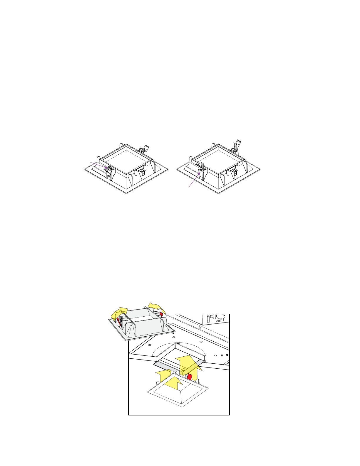
2. Attch butterfly brckets
a. Outside the housing, undo the red wing nut and washer attached to the first butterfly
bracket’s bolt.
b. Run the bracket’s bolt through the hole in the side of the housing. (see fig. 7)
c. Reaching into the housing, thread the washer and red wing-nut back onto the bolt, fixing the
bracket in place.
d. Repeat steps a-c for the second butterfly bracket.
fig. 7
3. Restore the original emitter module conditions
a. Return the emitter chassis to its original position, locking the tilt and rotation locks.
b. Wall-wash downlight only: Reattach the optic. Press it flush to the base of the emitter chassis and
turn it clockwise until it engages the shoulder screws on either side of the emitter.
Note: The opening in the c-shaped kick reflector should face the wall.
c. Reinsert the cardboard plug to protect the optic from dust during the rest of the installation.
continued on next page
10|D3 INSTALLATION GUIDE
© 2019 Ketra, Inc. All rights reserved
P/N 040444 Rev E

INSTALLATION
REVISIONS
ZONE
REV.
ECO DESCRIPTION
DATE
APPROVED
C
E
4. Mount downlight in ceiling
Note: For optimal radio communication, ensure that the radio dome is not above or adjacent to
anything metallic.
a. Use bar stock or C-channel (not provided) to mount the D3 in the ceiling. The supports should go
through the holes in the butterfly brackets and can be used to suspend the D3 without screws
(see fig. 8).
Note: After mounting, the D3’s collar will need to be flush to the ceiling plan or 0.0625 in (1.5875 mm)
above it.
b. Wire-tie at least one bracket to the deck using at least one tie.
fig. 8
5. Optional: If using a square aperture with a flange, realign the collar parallel to the wall.
a. Loosen the collar’s two outer screws, freeing the collar for rotation.
b. Realign the collar using its v-shaped notches and an alignment string or laser.
c. Re-tighten the screws to lock the collar’s new position.
© 2019 Ketra, Inc. All rights reserved
11|D3 INSTALLATION GUIDE
P/N 040444 Rev E

INSTALLATION
Prt 2: Wire the Fixture
1. Run power to junction box
a. A. Remove the junction box’s outer cover by pressing down on the outer latch and pulling the
cover toward you.
Note: A licensed electrician should perform all the wiring tasks. All electrical connections must
be made within the junction box.
b. Run the conduit in (and out, if this is one downlight in a sequence).
Note: Maximum of ( 8 ) no. 12 AWG through branch circuit conductors suitable for 75 ˚C
permitted in the box.
c. Run the building’s power line wires* into the junction box.
2. Splice the wires
a. Using the provided connectors, splice the D3’s flying leads into the building’s power. Make sure
the housing is grounded in accordance with local codes.
b. Replace the junction box’s outer cover.
3. Test the wiring
a. Apply power to the D3. The emitter should immediately come on to 3000 K (warm white).
Note: If the emitter comes on red, see Diagnostic Colors, page 18.
b. Wait several minutes while the D3 tests its installation conditions. Then use the color to
c. determine whether installation was successful:
• If the light stays at 3000 K, installation was successful. Continue to step d.
• If the light changes color, a problem has been detected.
Note: Magenta can indicate success or failure. It indicates success if there are no other
powered-on Ketra devices within 50 ft (15.24 m); otherwise, it indicates a problem.
To troubleshoot problems, see Diagnostic Colors, page 18.
d. After verifying a successful installation, remove power and continue to Part Three.
* Ketra lighting products should not be connected to, or directly controlled by, AC mains line voltage dimmers. These types of dimmers may also
be referred to as phase cut, triac, forward-phase, reverse-phase, ELV, or MLV dimmers. Ketra's lighting products should only be controlled via our
digital control architecture. Ketra does not recommend switching power on/o to Ketra lighting products via relays, contactors, or manual toggle
switches. When the lighting products are disconnected from power they cannot respond to digital commands from control devices. This could
confuse end users as the lighting may be in a state that is inconsistent with the control devices. Please refer to our controls products installation
guides for more information.
12|D3 INSTALLATION GUIDE
© 2019 Ketra, Inc. All rights reserved
P/N 040444 Rev E

INSTALLATION
Prt 3: Instlling Drywall
1. Ensure that the aperture is plugged with the cardboard insert to protect the optic.
2. Cut properly-sized hole in drywall before installing drywall. Reference table for sizes.
Type Hole shape and size
Mud-In Circle with 5.5 in (139.7 mm) diameter
Flanged with square aperture Square with 4 in (101.6 mm) length/width
Flanged with round aperture Circle with 4 in (101.6 mm) diameter
3. Align the hole with the D3's aperture and install the drywall.
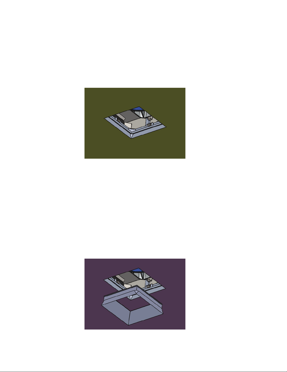
Part 4: Apply Mud-In Flnge Trim Retiner
Note: Skip this section if you have a flanged downlight.
1. Align the retainer assembly such that the holes in the retainer line up with the screw posts in the collar.
(see fig. 9)
2. Secure the retainer assembly using the #632 fasteners. For ceiling thickness in range 0.625 in (16.129
mm) to 1.125 in (28.575 mm), use the blue coded short set; for ceiling thickness in range 0.875 in
(225.425 mm) to 1.5 in (38.1 mm), use the red coded long set.
Note: The retainer assembly should be flush with the drywall.
fig. 9
13|D3 INSTALLATION GUIDE
© 2019 Ketra, Inc. All rights reserved
P/N 040444 Rev E
INSTALLATION
Prt 5: Apply Joint Compound
1. Apply skim coat up to the aperture rim using a joint compound. (For mud-in versions, cover the flange
but not the retainer.) For best results, use a full ceiling float (see fig. 10).
fig. 10
2. Sand and finish the final surface before removing the aperture plug. Clean the internal surfaces of the
trim retainer with a clean rag and isopropyl alcohol.
Prt 6: Apply Trim
Mud-in and flanged downlights have dierent processes for applying their trims. Please read only the
appropriate section below.
1. Applying trim to mud-in downlight
a. Press the flangeless trim into the trim retainer (see fig. 11).
continued on next page
14|D3 INSTALLATION GUIDE
fig. 11
P/N 040444 Rev E
© 2019 Ketra, Inc. All rights reserved
INSTALLATION
REVISIONS
REV.
ECO DESCRIPTION
DATE
APPROVED
01
INITIAL RELEASE
D
C
B
8
7
6
5
4
3
2
1
2. Applying trim to flanged downlight
If your ceiling’s substrate is thicker than 0.6251 in (16.12925.4 mm), adjust the springs on either side
of your trim:
a. Using a #1 screwdriver, loosen the screw holding the spring in place.
b. Raise the spring as high (as far from the bottom of the trim) as it will go.
c. Re-tighten the screw (see fig. 12).
fig. 12
3. Compress the springs and push into the downlight aperture until the trim is flush to the ceiling.
Ensure that the springs are properly compressed and are going into the collar, not around the collar.
(see fig. 13)
4. Snap the trim into the collar.
15|D3 INSTALLATION GUIDE
fig. 13
P/N 040444 Rev E
© 2019 Ketra, Inc. All rights reserved

Additionl Opertions
Tilt Rotation (Square Trim Only)
To Raise: Push To Lower: Pull
1. Re-aiming the optic
a. Remove the trim by pulling the trim directly down from the housing.
b. Unlock the emitter chassis: reach into the D3’s housing and unlock tilt lock and rotation lock levers
(both colored red). (see fig. 14)
c. Use the degree indicators to determine degree of rotation (square trim only) and tilt.
(see fig. 15)
fig. 13
fig. 14
fig. 15
2. Adjusting optic depth
a. Remove the trim by pulling the trim directly down from the housing.
b. To set optic at the deep regress position push optic directly up. Light engine will magnetically
lock into place (see fig. 16).
c. To set optic at the low regress position pull optic directly down. Light engine will magnetically
lock into place (see fig. 17).
16|D3 INSTALLATION GUIDE
fig. 16 fig. 17
© 2019 Ketra, Inc. All rights reserved
P/N 040444 Rev E

ADDITIONAL OPERATIONS
Align to Shoulder Pins and Insert Twist to Lock
Twist to Unlock (Rotation lock should be set) Pull to Remove (Optic is not tethered!)
3. Replacing the optic
a. Remove the trim by pulling the trim directly down from the housing.
b. Ensure that the emitter chassis is locked.
c. Grab optic and twist counterclockwise to unlock. Pull toward you to remove.
d. Install replacement optic, twisting clockwise to lock (see fig. 18).
fig. 18
4. Replacing the power supply
a. Remove the trim by pulling the trim directly down from the housing.
b. Tilt the Light Engine to 40°'s tilt and rotate to allow access to the power supply.
c. Unhook the emitter cable from the RJ45 jack on the power supply.
d. Pull power supply straight out from the docking station while depressing docking station latch.
e. Disconnect power supply quick connect (see fig. 19).
Tilt locked at 40˚. Emitter
Module in Full Regress
Unlocked and rotated so
that Emitter Module tilts
away from Power Supply
Disconnect power at the
Luminaire Disconnect
Disconnect
Emitter Module
17|D3 INSTALLATION GUIDE
© 2019 Ketra, Inc. All rights reserved
P/N 040444 Rev E

Troubleshooting
The D3 uses built-in tests to check wiring and wireless connectivity. These tests run each time the D3 turns
on, and may take several minutes.
Note: The D3 will NOT run these tests while provisioned to a Design Studio installation.
If the D3 find a problem, it will let you know by emitting a corresponding color or, if no emitter is
connected, by flashing the indicator lights on its power supply.
DIAGNOSTIC COLORS (REQUIRES EMITTER)
The D3 will emit a color to tell you the type of problem.
Color Condition Correction
Red Invalid input voltage on the
power line
Magenta Poor wireless connectivity Ensure that the D3 is not in a metal enclosure and
Yellow Fair wireless connectivity Ensure that the D3 is not in a metal enclosure
Note: Magenta can indicate success or failure. It indicates success if there are no other powered-
on Ketra devices within 50 ft (15.24 mm); otherwise, it indicates a problem.
Ensure that input voltage matches the expected
voltage for the D3's model.
that there are no significant obstructions between
the D3 and other Ketra devices.
Note: In some circumstances, magenta is expected.
See the note below the table.
and that there are no significant obstructions
betweenthe D3 and other Ketra devices.
18|D3 INSTALLATION GUIDE
© 2019 Ketra, Inc. All rights reserved
P/N 040444 Rev E

Wrrnty Tech Support
Limited warranty terms can be found at:
www.ketra.com/warranty
For questions and technical support please contact:
(844) 5886445
ketrasupport@lutron.com
Ketra and KetraNET are trademarks or registered trademarks of Lutron Ketra LLC, in the US and/ or
other countries.
19|D3 INSTALLATION GUIDE
© 2019 Ketra, Inc. All rights reserved
P/N 040444 Rev E

6231 E. Stssney Ln.
ketra.com
P/N 040444
Bldg. 13, Suite 400
Austin, TX 78744
P/N 040444 Rev D
ketr.com
512.872.4349
 Loading...