

Page 1

QUICK START GUIDE
K es t r e l E l i t e & S p o r t s m a n
Wea t h e r M e t e r s w i t h A p p l i e d B a l l i s t i c s
Page 2

13
12
The Kestrel employs a stable, accurate pressure sensor to
measure station pressure, the unadjusted air pressure in
your location.
» To use your Kestrel to measure barometric pressure
(station pressure adjusted for local elevation), you
must enter a correct reference value for your altitude.
Accurate barometric readings require that no elevation
changes be made while taking measurements.
» To use your Kestrel to measure altitude changes
(changes in station pressure associated with changes
in elevation), you must enter a correct reference
value for your starting barometric pressure. Accurate
altitude readings depend on stable, weather related
barometric air pressure while measurements are taken.
» Synched values between the Altitude and Barometer
measurement screens allow reference value updates
on either screen to automatically update reference
values on the other. You cannot use your Kestrel as a
barometer and altimeter simultaneously.
ALTIMETER AND BAROMETER
SETTING REFERENCE VALUES ON BARO
MEASUREMENT SCREEN:
» Scroll to the Baro measurement screen and
select Settings.
» Adjust either the Altitude or the Barometric
Pressure value to a local, known value obtained
from a mapping reference, GPS, or accurate
weather station in the same location.
SETTING REFERENCE VALUES ON ALTITUDE
MEASUREMENT SCREEN:
» Scroll to the ALTITUDE measurement screen
and select Settings.
» Adjust either the Altitude or the Barometric
Pressure value to a local, known value obtained
from a mapping reference, GPS, or accurate
weather station in the same location.
Note! You should enter new reference values whenever you are
using the Altimeter or Barometer functions and your location or
the weather cond itions have chan ged.
Note! You do NOT need to ent er Altimeter or B arometer
reference valu es to obtain accurate ba llistics targe ting solutions .
The ballisti cs calculator em ploys the station p ressure.
Don’t forget! Set your Operating Mode to Ballistics on
the Options Menu to use Ballistics features!
For ease of access, the ballistics Targeting Screen also
contains the Ballistics Menu. Simply scroll down from the
Targeting Screen to access these settings and submenus:
» Target
» Wind
» Gun
» Environment
» Range Card
(Elite Model onl y)
» Ballistics (Limited on Sportsman model, full on Elite model)
» Manage Guns
Note! The back o f this guide contains a f ull Glossar y of the terms used.
Please read these denitions!
CREATE OR EDIT A GUN PROFILE:
» Scroll to and select Manage Guns. Either select an
existing gun to edit or select New Gun.
» Scroll up and select Gun to rename the gun. Use the
scroll/adjust buttons to enter a new name, then exit
the naming menu.
» Set the remaining values in the Gun sub menu to
match your gun, bullet and scope combination.
CREATING GUN & BULLET PROFILES
EDIT TARGET:
» Scroll to and select Tgt .
» Set range, angle, target speed, and wind values
to match your target.
EDIT TARGET OR CREATE ADDITIONAL TARGETS:
(Elite model only)
» Scroll to and select Tgt .
» Set range, angle, target speed, and wind values
to match your target.
The elite model allows up to ve targets (A TO E).
» Make sure Target is set to Active.
» To enable more than one target, or edit other
active targets, scroll up to the header named
Target and use the left/right buttons to scroll
between targets (A through E). Set a target to
Active to enable it, then edit its values.
» When only one target is active, its range can also
be modied directly from the main Targeting
Screen by highlighting Tgt and scrolling left or
right.
» If more than one target is set to Active,
highlighting Tgt in the main Targeting screen
and scrolling left or right will scroll between
active targets.
CREATING TARGETS
Shop for Quality products online at:
1.888.610.7664
www.
SCOUTBASECAMP
.com
Page 3
5
4
CONTENTS
Measurements And Features ............................ 5
Getting To Know Your Kestrel ............................ 6
Buttons .................................................................. 7
Kestrel Options Menu ......................................... 8
Kestrel Operating Mode ..................................... 8
Kestrel Menu Navigation ................................... 9
Weather Mode Screen ........................................ 10
Getting Started .................................................... 11
Additional Settings ............................................ 11
Altimeter And Barometer ................................... 12
Creating Gun & Bullet Proles ........................... 13
Creating Targets ..................................................13
Measuring Wind .................................................. 14
Calibrating Muzzle Velocity ............................... 15
Calibrating Drop Scale Factor ...........................16
Environment ......................................................... 17
Continuous Wind Capture .................................. 17
Connecting To Devices Using Link ................... 18
Weather Glossary................................................. 20
Target Menu .........................................................21
Gun Menu ............................................................. 21
Environment Menu ............................................. 23
Ballistics/Range Card Menu ............................... 23
Impeller Replacement ........................................ 25
Warranty Certicate ............................................26
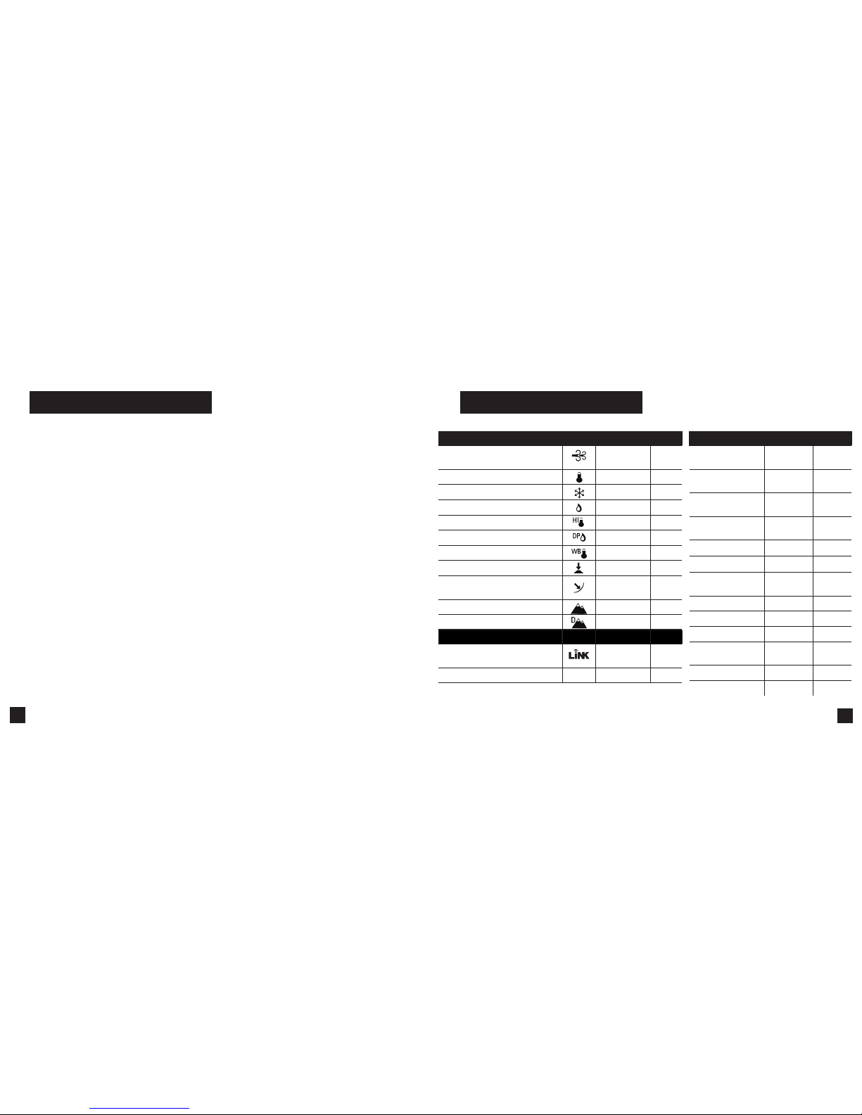
Measurements Icon Sportsman Elite
Wind Speed | Air Speed
(mph | fpm | m/s | km/h | kt)
• •
Temperature (˚F | ˚C)
• •
Wind Chill (˚F | ˚C)
• •
Relative Humidity (%)
• •
Heat Stress Index (˚F | ˚C) .
• •
Dewpoint Temp (˚F | ˚C)
• •
Wet Bulb Temp (˚F | ˚C)
• •
Station Pressure (Absolute Pressure)
• •
Barometric Pressure (inHg | hPA |
psi | mb)
• •
Altitude, m | ft
• •
Density Altitude, m | ft
• •
Features Sportsman Elite
LiNK Wireless Connectivity + LiNK
Ballistics Mobile App
•
(optional)• (optional)
Night Vision Preserving Back Light
NV
• •
Measurements Sp ortsman Elite
G1/G7 Ballistic
Solver
• •
Muzzle Velocity
Calibration
• •
Target Range
Estimator
• •
Muzzle VelocityTemperature Table
• •
Spin Drift
• •
Coriollis Correction
• •
Aerodynamic Jump
Correction
• •
Gun Memory
3 16
Targets
1 5
Ballistics Data
Limited Full
AB Custom Drag
Models
•
Range Card
•
DSF Calibration
•
MEASUREMENTS AND FEATURES
Shop for Quality products online at:
1.888.610.7664
www.
SCOUTBASECAMP
.com
Page 4
7
6
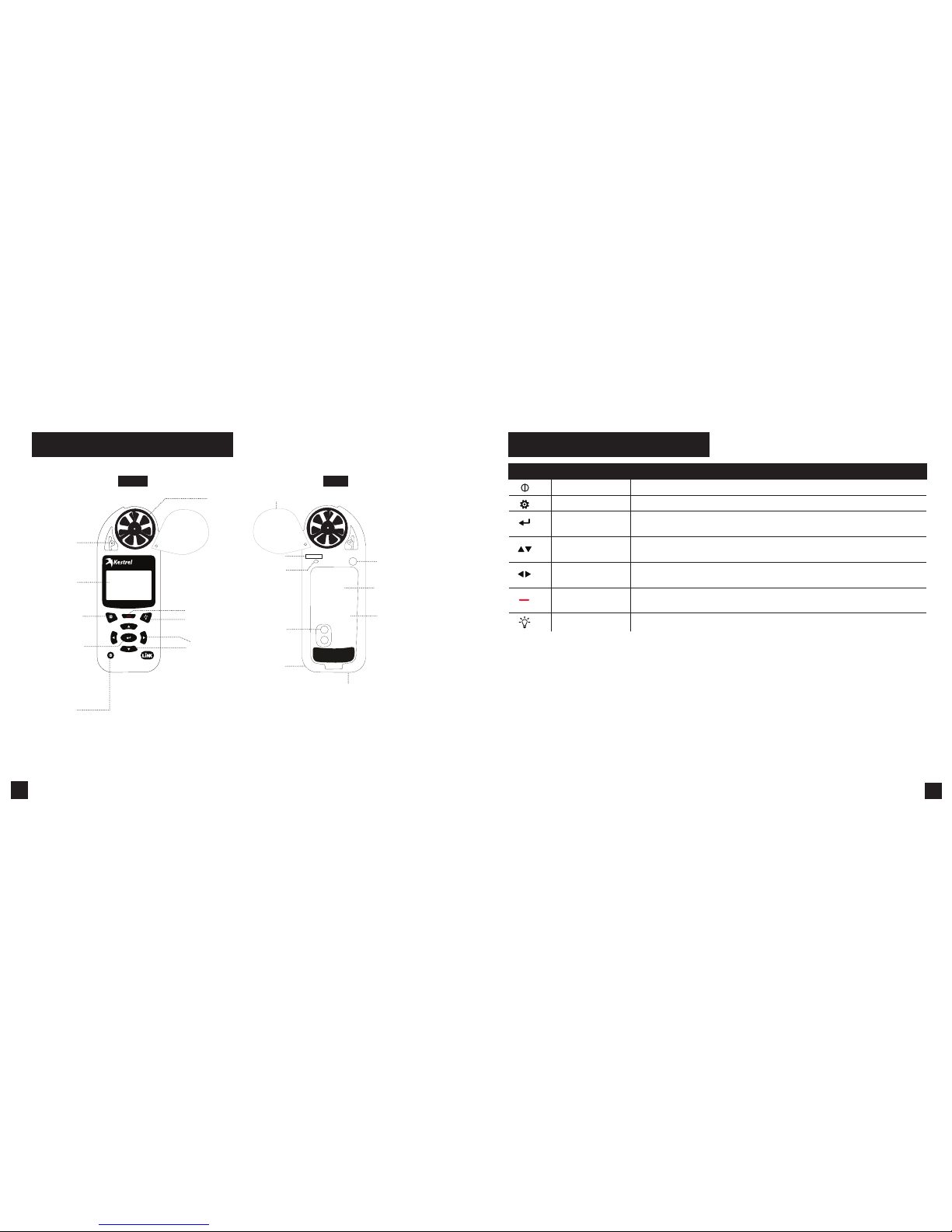
GETTING TO KNOW YOUR KESTREL
BACK
DATA TRANSFER
PORT
SERIAL NUMBER
AA BATTERY (1)
(Lithium recommended)
LANYARD
ATTACHMENT
PRESSURE
SENSOR
FRONT
OPTIONS/EXIT
POWER
BACKLIGHT
SCROLL/ADJUST
TEMPERATURE
SENSOR
REPLACEABLE
IMPELLER
SELECT
BATTERY DOOR LATCH
HUMIDITY SENSOR
BATTERY DOOR
IMPELLER COVER
CAPTURE
SUNLIGHT
READABLE
DISPL
AY
BUTTONS
Button Name Function
POWER Turns Kestrel on and o. Press for on, hold for two seconds to turn o.
OPTIONS/ EXIT Enter the main Options menu or exit a menu.
SELECT Access Settings on any measurement screen or select a menu option to enter its
submenu or conrm a task.
UP/DOWN Scroll up and down through measurement screens or menus. Adjust values when
entering text in name menus.
LEFT/RIGHT Scroll options left and right. Adjust values in combo menus and setting sub-
menus.
CAPTURE In Weather Mode, manually capture all environmental values. In Ballistics mode,
turns on and o continuous wind capture.
BACKLIGHT Turn backlight on or o. (Also turns o automatically after one minute.)
Shop for Quality products online at:
1.888.610.7664
www.
SCOUTBASECAMP
.com
Page 5
9
8
Most system-wide and weather setup options are accessed
from the main Options menu by pressing the
button
from any Weather Measurement Screen or the main
Targeting Screen.
• MODE
• BLUETOOTH
» Bluetooth On/O
» Conct
• DATA PORT
• MEMORY OPTIONS
» Clear Log
» Auto Store
» Store Rate
» Overwrite
• GRAPH SCALE
• DISPLAY
» Auto Shutdown
» Contrast
» Backlight
• SYSTEM
» Time & Date
» Compass Cal
» Measurements
» Units
» Lang
» Batt
» Factory Restore
• ABOUT
» Version
» Legal
KESTREL OPTIONS MENU
Your Kestrel Ballistics Weather Meter is both a
complete weather meter AND an advanced
ballistics calculator. You must select either Weather
Mode or Ballistics Mode depending on the functions
you desire:
» Weather Measurements, History and Data Logs are
accessed in Weather Mode.
» The Targeting Screen and all ballistics settings
(Target, Wind, Gun, Environment, Range Card,
Ballistics, Manage Guns) are accessed in Ballistics
Mode.
HOW TO SELECT THE OPERATING MODE:
» Select Mode under the Options Menu.
» Set Mode to Weather or Ballistics.
NOTE! You can also “jump ” between mo des by pressing the
BACKLIGHT but ton twice quick ly. You will enter Weather M ode at
the last Measure ment Screen used , making it conveni ent to take
advanced wind averaging measurements, for example.
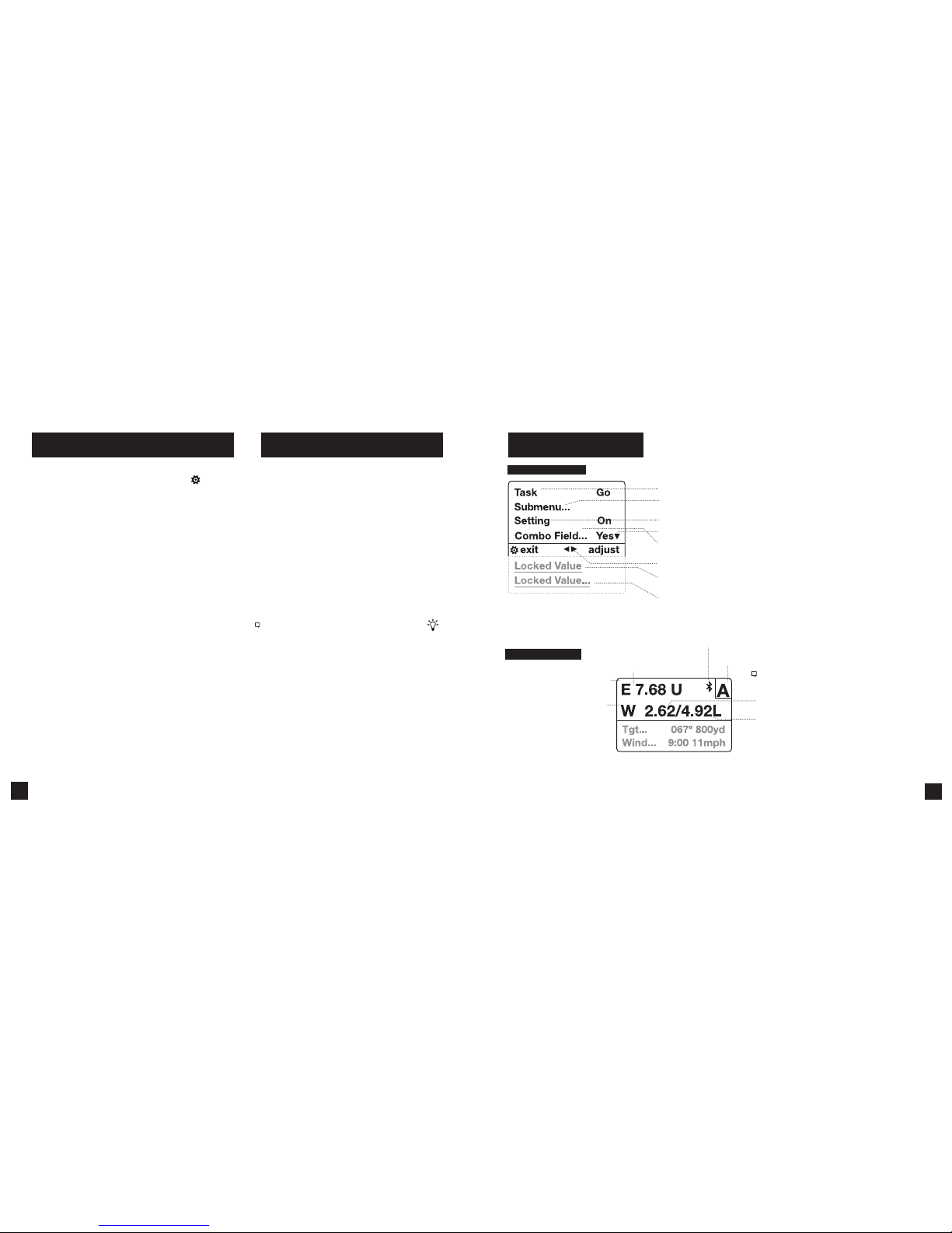
KESTREL OPERATING MODES KESTREL MENU NAVIGATION
TYPES OF MENU ITEMS
TARGETING SCREEN
Note! The Windage Adjustment provides two values
creating a wind pro le bracket based on a 5 se cond
rolling average shown.
Windage soluti on based on the average w ind speed.
Shown on Range Card as Wn d1.
Windage soluti on based on the maxi mum wind speed.
Shown on Range Card as Wn d 2.
* Range Card avail able on Elite Mod el only.
SCOPE ELEVATION ADJUSTMENT
(U=U p/D=Do wn)
SCOPE WI NDAGE ADJUS TMENT
(L = Left, R = Ri ght)
Targeting Screen
Active Target (Elite Mo del only)
Bluetooth ® Connection St atus
» Tasks are executed by highlighting the eld and pressing Select.
» The presence of a submenu is indicated by a “…” following a eld.
» Highlight the eld and press Select to enter a submenu.
» Adjust the value of a Combo Field by pressing left or right.
» Enter the Combo Field sub menu by pressing select.
» Adjust a setting by pressing left or right.
» An arrow indicates there are additional elds o screen.
» Locked values are either driven by another value or cannot be edited on
the current screen.
» Locked values may have submenus which are entered by pressing select.
» Navigation buttons indicate available actions on the current screen.
Shop for Quality products online at:
1.888.610.7664
www.
SCOUTBASECAMP
.com
Page 6

11
10
Measurement
& Icon Units
WEATHER MODE SCREENS
Graph of Store d Data Log
Data Point Value
Data Point Scro ll Bar
Current Measurement Screen
Press
SELECT to enter settings
menu for that measurement.
Min Ave Max Screen
Press
SELECT to sta rt, stop
and clear the M in/Avg/Max
tracking.
Data Graph Screen
Press
SELECT to enter
the Data Log D etail Screen to
view logge d data points .
Data Points Screen
Press LEFT/RIG HT to scroll through
data point s. Press OPTIO NS to exit
Data Log Det ails Screen.
MORE MEASUREMENTS
MORE MEASUREMENTS
Data Point Tim e Stamp
» The UP/DOWN buttons navigate between all weather
measurements set to “On” in Options|Measurements.
» The
LEFT/RIGHT buttons scroll between the three
display screens for the measurement.
» The
OPTIONS button exits the settings submenu
and Data Log Detail Screen.
1. INSTALL BATTERY. Slide the battery door latch and
open door. Insert the provided AA lithium battery
as indicated by the label. Replace the battery door,
ensuring it “clicks” fully into place.
2. POWER ON KESTREL. Press
to power on Kestrel.
3. ENTER OPTIONS MENU. Press
to enter the Options
Menu.
4. CALIBRATE THE COMPASS. Scroll to and select
System. Scroll to and select Compass Cal. Follow the
on-screen instructions:
» Place the base of the Kestrel on a
at surface at least 3 feet from any
large metal objects.
» Start the calibration routine.
Rotate the Kestrel around its
vertical axis 3 times, keeping the
unit as vertical as possible and
taking approximately 10 seconds
per full rotation. You may need to
restart the routine a few times until
you get the timing correct.
Note! When taki ng compass readi ngs,
keep the Kestrel a s vertical as poss ible for
maximum accuracy.
5. EXIT OPTIONS MENU.
GETTING STARTED
All additional settings are accessed from the
options menu.
1. SET AUTO SHUTDOWN. Scroll to and select
Display. Scroll to Auto Shtdwn and choose a
time window after which the Kestrel will shut
down without any button presses.
2. SET BACK LIGHT. Scroll to and select Display.
Scroll to Backlight and set to either standard
White or night vision preserving Red.
3. SET DATE AND TIME. Scroll to and select System.
Scroll to and select Time & Date. Adjust the time
and date.
4. TURN ON/OFF MEASUREMENT SCREENS.
Scroll to and select System. Scroll to and select
Measurements. Set each measurement screen
to either On or O as desired.
5. SET UNITS. Scroll to and select System. Scroll
to and select Units. To change all units select
Global, then set Global to Imperial or Metric,
and then scroll to Apply and select Go. To set
units individually, scroll to each measurement
type in the Units submenu and set to the desired
units. Units can also be set in the Settings menu
for each measurement.
3x
Scroll/Adjust
Select
BUTTON QUICK KEY
Options/Exit
ADDITIONAL SETTINGS
Shop for Quality products online at:
1.888.610.7664
www.
SCOUTBASECAMP
.com
Page 7

13
12
The Kestrel employs a stable, accurate pressure sensor to
measure station pressure, the unadjusted air pressure in
your location.
» To use your Kestrel to measure barometric pressure
(station pressure adjusted for local elevation), you
must enter a correct reference value for your altitude.
Accurate barometric readings require that no elevation
changes be made while taking measurements.
» To use your Kestrel to measure altitude changes
(changes in station pressure associated with changes
in elevation), you must enter a correct reference
value for your starting barometric pressure. Accurate
altitude readings depend on stable, weather related
barometric air pressure while measurements are taken.
» Synched values between the Altitude and Barometer
measurement screens allow reference value updates
on either screen to automatically update reference
values on the other. You cannot use your Kestrel as a
barometer and altimeter simultaneously.
ALTIMETER AND BAROMETER
SETTING REFERENCE VALUES ON BARO
MEASUREMENT SCREEN:
» Scroll to the Baro measurement screen and
select Settings.
» Adjust either the Altitude or the Barometric
Pressure value to a local, known value obtained
from a mapping reference, GPS, or accurate
weather station in the same location.
SETTING REFERENCE VALUES ON ALTITUDE
MEASUREMENT SCREEN:
» Scroll to the ALTITUDE measurement screen
and select Settings.
» Adjust either the Altitude or the Barometric
Pressure value to a local, known value obtained
from a mapping reference, GPS, or accurate
weather station in the same location.
Note! You should enter new reference values whenever you are
using the Altimeter or Barometer functions and your location or
the weather cond itions have chan ged.
Note! You do NOT need to ent er Altimeter or B arometer
reference valu es to obtain accurate ba llistics targe ting solutions .
The ballisti cs calculator em ploys the station p ressure.
Don’t forget! Set your Operating Mode to Ballistics on
the Options Menu to use Ballistics features!
For ease of access, the ballistics Targeting Screen also
contains the Ballistics Menu. Simply scroll down from the
Targeting Screen to access these settings and submenus:
» Target
» Wind
» Gun
» Environment
» Range Card
(Elite Model onl y)
» Ballistics (Limited on Sportsman model, full on Elite model)
» Manage Guns
Note! The back o f this guide contains a f ull Glossar y of the terms used.
Please read these denitions!
CREATE OR EDIT A GUN PROFILE:
» Scroll to and select Manage Guns. Either select an
existing gun to edit or select New Gun.
» Scroll up and select Gun to rename the gun. Use the
scroll/adjust buttons to enter a new name, then exit
the naming menu.
» Set the remaining values in the Gun sub menu to
match your gun, bullet and scope combination.
CREATING GUN & BULLET PROFILES
EDIT TARGET:
» Scroll to and select Tgt .
» Set range, angle, target speed, and wind values
to match your target.
EDIT TARGET OR CREATE ADDITIONAL TARGETS:
(Elite model only)
» Scroll to and select Tgt .
» Set range, angle, target speed, and wind values
to match your target.
The elite model allows up to ve targets (A TO E).
» Make sure Target is set to Active.
» To enable more than one target, or edit other
active targets, scroll up to the header named
Target and use the left/right buttons to scroll
between targets (A through E). Set a target to
Active to enable it, then edit its values.
» When only one target is active, its range can also
be modied directly from the main Targeting
Screen by highlighting Tgt and scrolling left or
right.
» If more than one target is set to Active,
highlighting Tgt in the main Targeting screen
and scrolling left or right will scroll between
active targets.
CREATING TARGETS
Shop for Quality products online at:
1.888.610.7664
www.
SCOUTBASECAMP
.com
Page 8

15
14
An accurate crosswind measurement requires that the
Kestrel “know” both the direction of re and the wind
direction and strength. You may use the Kestrel’s built-in
compass and wind measuring and averaging features to
capture these values:
CAPTURING THE DIRECTION OF FIRE:
» Select Tgt to enter the Target menu, scroll down and
select DoF, then scroll down and select Capture.
» Follow the on-screen instructions:
» While holding the Kestrel vertical, point the back
of the unit directly towards the target and select
Capture.
» DoF will automatically be populated in the Target
menu.
MEASURING WIND
CAPTURING THE WIND INPUTS:
» In the Target menu, scroll down and select WD,
WS1, or WS2.
» Scroll down and select Capture.
» Follow the on-screen instructions:
» While holding the Kestrel vertical, point the
back of the unit directly into the wind and
select Capture.
» Continue to point the Kestrel into the wind
for at least 5 seconds to capture a sample of
the winds. Select End Capture.
» WD, WS1, WS2 will automatically be populated
in the Target menu.
Note! Select ing Wind in the Bal listics Menu ju mps directly to t he
WD, WS1, & WS2 entries in the Target M enu.
Note! For maxi mum accuracy of com pass readings wh en
capturing Do F and Wind, the Kest rel must be held as ve rtically
as possible – be ca reful not to tilt it a way from you while ta king
readings.
Note! Any time you a re using the Kestrel t o calculate an eleva tion
hold (includi ng when calibrat ing muzzle velo city and DSF) a
direction of re plus wind direc tion and spee ds must be input.
These inputs contribute to an accurate elevation solution.
The Muzzle Velocity Calibration function allows you to
obtain a more accurate muzzle velocity by combining
user input data and actual shot results and calculating the
actual bullet speed.
CALIBRATING MUZZLE VELOCITY:
» Scroll to and select Gun in the Ballistics Menu.
» After accurately inputting all other gun, bullet, and
scope parameters, as well as wind values and direction
of re, scroll to MV and adjust to your best estimate of
your gun’s muzzle velocity.
» Select MV to enter the MV sub menu. Scroll to and
select Cal MV.
» The Cal MV range is the suggested target distance
at which to calibrate. For best results, nd a range
where you can shoot to between 90% and 100% of the
recommended range but no further. Calibrating at less
than 90% of the recommended range will lessen accuracy and less than 80% or beyond the recommended
range will not be valid.
» Adjust Range to match the actual distance to your
target where you are shooting. Accuracy here is key!
Use a quality ranger nder if you are not on a measured
range.
» Apply the suggested elevation hold shown in Drop in
your scope turrets or reticle.
CALIBRATING MUZZLE VELOCITY
» Take a number of shots to determine the actual
bullet drop. Adjust Drop to match the actual
observed bullet drop of the bullet at that range.
For example, if the point of impact is 1.5 Mils
below the bullseye adjust the Drop value to be
1.5 Mils greater.
» A new MV will be automatically calculated to
match the actual impact of your round. (In this
example, the MV will be decreased.) No chrono-
graph required!
» A (+) or (-) in front of the MV value indicates the
new MV has been calibrated up or down.
» Exit to accept the new MV value.
Note! The sugge sted MV Cal range is the d istance where the bu llet
slows to Mach 1.2. If th e suggested range c annot be matched i t
is better to sho ot at a shorter/closer d istance rather than f urther.
However, as the MV cali bration range dec reases, so does MV
calibration acc uracy. Try to shoot as clo se to the recommend ed
MV Cal range as possi ble.
Note! If the MV-Temp table ha s been popula ted, MV values
will be locked b y the MV-Temp table and MV values w ill not be
automaticall y adjusted by the MV Ca l procedure abo ve.
Shop for Quality products online at:
1.888.610.7664
www.
SCOUTBASECAMP
.com
Page 9

17
16
The Drop Scale Factor (DSF) function allows you to
calibrate the BC of your round beyond the supersonic
range of the bullet and maintain accurate solutions out to
transonic and subsonic ranges. DSF calibration does not
impact the supersonic ight path of the bullet.
CALIBRATING DSF:
» Scroll to and select Gun in the Ballistics Menu.
» After accurately inputting all other gun, bullet, and
scope parameters, as well as MV, wind values and
direction of re, scroll to and select CAL DSF.
» The Cal DSF range is the suggested target distance at
which to calibrate. For best results, nd a range where
you can shoot to at least 90% of the recommended
range. Calibrating at less than 90% of the recommended range will lessen accuracy and less than 80%
of the recommended range will not be valid. Calibrating DSF at distances beyond the recommended Cal
DSF range is ok.
» Adjust Range to match the actual distance to your
target where you are shooting. Accuracy here is
key! Use a quality ranger nder if you are not on a
measured range.
» Apply the suggested elevation hold shown in Drop in
your scope turrets or reticle.
» Take a number of shots to determine the actual bullet
drop. Adjust Drop to match the actual observed bullet drop of the bullet at that range. For example, if the
point of impact is 1.5 Mils below the bullseye, adjust
the Drop value to be 1.5 Mils greater.
» A new DSF value will be automatically calculated
to match the actual impact of your round in the
transonic or subsonic range.
» A (+) or (-) in front of the DSF value indicates the
DSF value has been calibrated up or down. A
DSF value of 1 indicates no change to BC in the
transonic or subsonic range.
» Exit to accept the new DSF value.
» Up to 6 DSF values can be created to calibrate
BC through the transonic and subsonic range.
Calibrating DSF one time can create more than
one DSF Cal value.
» All DSF values can be viewed and deleted in
View DSF.
Note! Entering DSF va lues at a shorte r range than a previ ously
entered DSF value wi ll overwrite th e longer range val ue.
CALIBRATING DROP SCALE FACTOR AVAILABLE ON ELITE MODELS ONLY
Accurate Temperature, Humidity and Pressure
measurements are critical to calculating an accurate
Targeting Solution. It is important that the values
measured by the Kestrel represent the ambient values,
and for this the Kestrel needs continuous airow over
its sensors. When using a Kestrel in a position where
airow could be restricted, such as low to the ground
or resting on a shooting mat or rock, it is better to make
periodic environmental captures to avoid inaccurate
measurements.
HOW TO CAPTURE ENVIRONMENTAL MEASUREMENTS:
» In the Ballistics Menu, scroll to and select
Environment then scroll to Update.
» Adjust Update to Yes and then wave the Kestrel
rapidly through the air for 5-10 seconds. If the area
allows, and your lanyard is secure, you may also “sling”
the Kestrel around by the lanyard.
» Immediately adjust Update back to No to x the
environmental measurements you have just captured.
NOTE! Repeat th is process ever y half hour or any time the temperature or
pressure changes signicantly.
HOW TO SET THE LATITUDE:
Latitude is necessary for accurate Coriolis calculations.
» In the Ballistics Menu, scroll to and select
Environment then scroll to Lat.
» Adjust Lat to match your local latitude.
NOTE! Latitude d efault is the midd le of North Ame rica if no new
value is entered . Setting both D oF and Lat to 0 will e ectively turn Co riolis
correction o.
ENVIRONMENT
As an alternative to the Wind Capture method
described previously, you may mount your Kestrel
on a tripod using the Kestrel Vane Mount. The Vane
Mount ensures the Kestrel remains oriented into
the wind and allows for continuous update of the
windage solution. For convenience, this method
works best when the ring solution is being displayed
on a mobile device using Kestrel LiNK Ballistics.
HOW TO SET THE KESTREL TO CONTINUOUS
WIND CAPTURE
» Select the correct Gun and Target and set the
Direction of Fire.
» In the Ballistics Menu, highlight Wind and press
the red Capture button. An arrow will appear next
to the Wind menu item to indicate the unit is now
in wind capture mode.
» While in wind capture mode, manual inputs to the
unit will be locked and changes in wind speed or
direction will automatically update the Targeting
Screen Windage solution.
» To close wind capture press the red Capture
button again.
CONTINUOUS WIND CAPTURE
Shop for Quality products online at:
1.888.610.7664
www.
SCOUTBASECAMP
.com
Page 10

19
18
If your Kestrel is marked LiNK on the bottom front label,
it can be connected wirelessly to other LiNK-compatible
devices. LiNK is powered by Bluetooth Smart®, also known
as Bluetooth® LE, which is available in most iOS devices
released after 2014 and Android devices released after
2015, as well as in a USB Dongle available from Kestrel that
supports connectivity to Windows and Mac OS devices.
LiNK-enabled Kestrel units can connect to mobile devices
running Kestrel LiNK Ballistics allowing you to view your
targeting solutions remotely, build and manage gun
proles, access the Applied Ballistics custom drag models
and install rmware updates. LiNK-enabled units can can
be run wirelessly to computers using the Kestrel Dongle.
On Windows PC’s use the Applied Ballistics Prole Loader
to create and install gun proles and access the Applied
Ballistics custom drag model library. (Applied Ballistics
custom drag models can only be used in Elite model
Kestrel meters.)
CONNECTING TO DEVICES USING LINK
your computer. Insert your Kestrel USB Dongle
(available separately) into an open USB port.
» On the Kestrel, open the Options Menu and
select Bluetooth. Set Bluetooth to On. Set
Conct to PC/Mobile mode, the Kestrel’s Status
will change to Available, indicating that it is
available for pairing with a computer or mobile
device.
» Ensure the computer or mobile device is
searching and in range. When Status changes
from Available to Connected, the pairing is
active and your Kestrel is ready to communicate.
CONNECTING TO A NEW LINK-COMPATIBLE
DEVICE: (SUCH AS A RANGE FINDER)
» Follow directions for your LiNK-compatible
Device to power it on and put it in pairing mode.
» On the Kestrel, open the Options Menu and
select Bluetooth. Set Bluetooth to On.
» Set Conct to Device.
» Scroll to Name and select New, then wait for the
list of available devices in range to populate.
» Select a device from the available list. Once
connected, the settings menu for that device
will open, allowing you to manage the device’s
settings.
» Exit to the Bluetooth menu. Status should
indicate Connected, meaning the pairing is
active and your Kestrel is ready to communicate.
CONNECTING TO/ADJUSTING A PREVIOUSLY PAIRED
LINK-COMPATIBLE DEVICE:
» Follow the directions for connecting to a new device
except instead of selecting New in the Name eld,
scroll left or right to nd the desired device.
» Status will change to Searching. If the device is in
range and in active pairing mode, a connection will
be made and Searching will change to Connected,
indicating that the pairing is active and your Kestrel
is ready to communicate.
BLUETOOTH CONNECTION INDICATOR:
» When connected to any LiNK compatible device,
a
icon will appear in the Targeting screen in the
upper right.
» If the paired device goes to sleep or if the
connection is lost, the
icon may disappear but
waking the device up or returning within range
should automatically reestablish the connection and
the icon should reappear.
Note! LiNK rang e is typically 100 f t/30M lin e of sight. Shorte r distances
should be ex pected if there a re obstacles such as w alls or metal
enclosures. R ange is also impac ted by the signal st rength of the othe r
device.
CONNECTING TO COMPUTERS USING USB CABLE
All Kestrel 5 Series units can connect to a computer via
the Data Transfer Port using the USB Data Transfer Cable
available separately. Kestrel LiNK software is available
for Windows and Mac for downloading logged weather
data and installing rmware updates. Applied
Ballistics Prole Loader is available for Windows only
and can be used to create and install gun proles
and access the Applied Ballistics Custom Drag Model
Library. (Applied Ballistics Custom Drag Models can
only be used in Elite units.)
to
o
t
Shop for Quality products online at:
1.888.610.7664
www.
SCOUTBASECAMP
.com
Page 11

21
20
WEATHER GLOSSARY
DIRECTION – Compass heading in true or magnetic North.
WIND SPD – Wind Speed is the measurement of the wind
passing through the impeller. For greatest accuracy, point the
back of the Kestrel directly into the wind.
CROSWND – Crosswind uses the internal compass and a user
selected heading to calculate the crosswind component of
the full wind.
HEADWND – Headwind uses the internal compass and a
user selected heading or target direction to calculate the
headwind component of the full wind.
TEMP – Ambient Temperature is the temperature measured
at the thermistor. For best results, ensure the thermistor
is not exposed to direct sunlight and is exposed to good
airow.
CHILL – Wind Chill is a calculated value of the perceived
temperature based on temperature and wind speed.
HUMIDITY – Relative Humidity is the amount of moisture
currently held by the air as a percentage of the total possible
moisture that the air could hold.
HEAT INDEX – Heat Index is a calculated value of the
perceived temperature based on temperature and relative
humidity.
DEW POINT – Dew Point is the temperature at
which water vapor will begin to condense out of
the air.
WET BULB – Wet Bulb is the lowest temperature
that can be reached in the existing environment by
cooling through evaporation. Wet Bulb is always
equal to or lower than ambient temperature.
BARO – Barometric Pressure is the local station
(or absolute) pressure adjusted to mean pressure.
An accurate reading depends on a correct altitude
input and unchanging altitude while measuring.
ALTITUDE – Altitude is the vertical distance
associated with given atmospheric pressure.
An accurate reading depends on correct initial
barometric pressure input and stable barometric
pressure while measuring.
STATION – Station Pressure (Absolute Pressure)
is the pressure exerted by the atmosphere at the
location.
DENS ALT – Density Altitude is the altitude at
which the density of the theoretical standard
atmospheric conditions (ISA) would match the
actual local air density.
Active – Setting a target to active makes it selectable
in the main target screen.(Not available in Sportsman
models)
TR – Target Range is the distance from the muzzle of the
rie to the target.
DoF – Direction of re is the direction from the position
of the shooter to the target.
Ideg – Inclination is the angle above or below horizontal
from the position of the shooter to the target.
Icos – Inclination Cosine is the cosine of the angle above
or below horizontal from the position of the shooter to
the target.
TS – Target Speed is the speed of the target
perpendicular to the direction of re.
TD – Target Direction is the direction of travel of the
target perpendicular to the direction of re.
WD – Wind Direction is the direction the wind is coming
from in relation to the direction of re.
WS1 – Wind Speed 1 is a ve second rolling average
wind speed.
WS2 – Wind Speed 2 is a ve second rolling maximum
wind speed.
MV – Muzzle Velocity is the speed of the bullet as it leaves
the muzzle. MV can be measured with a chronograph or
calculated using the MV Cal function. An MV estimate is
often provided by cartridge manufacturers or in reloading
manuals.
DM – A Drag Model is the known aerodynamic drag prole
of a standard projectile against which an actual bullet is
referenced. Ballistics coecients based on G1 drag models
are more widely available, ballistic coecients based on
G7 drag models are more representative of a typical hollow
tip, boat tail bullet. (Applied Ballistics Custom Drag Models
– Using one of the Applied Ballistics custom drag models
replaces the use of a standard projectile drag model and it’s
associated BC. When a custom drag model is used, the BC
value appears as a 1. Applied Ballistics custom drag models
can only be used in Elite units.)
BC – A Ballistic Coecient is a ratio that represents the ability
of the bullet to overcome air resistance and maintain velocity
while in ight in comparison to a standard projectile. Be sure
to match the G1/G7 drag model setting to the BC value you
are using. G1 BCs can not be used with G7 drag models and
vice-versa.
BW – Bullet Weight is the weight of the bullet measured in
grains or grams.
BD – Bullet Diameter is the diameter of the bullet measured
in inches or millimeters. (Note! Ensure bullet diameter is
correct. The given name of a bullet’s caliber does not always
match its actual diameter, for example 300WM is actually
.308”, not .300”)
TARGET MENU GUN MENU
Shop for Quality products online at:
1.888.610.7664
www.
SCOUTBASECAMP
.com
Page 12

23
22
BL – Bullet Length is the length of the bullet measured in
inches or millimeters. Automatically calculated from bullet
weight. May be overriden if actual bullet length is known.
ZR – Zero Range is the distance from the muzzle to the
target at which the rie was zeroed.
BH – Bore Hight (Scope Height) is the distance from the
center axis of the rie barrel to the center axis of the
scope. This can be measured from the top of the bolt to
the middle of the windage turret plus half the diameter of
the bolt.
ZH –Zero Height is a modication to impact elevation at
zero range, often used when adding a suppressor or using
a subsonic load. (Not available in Sportsman models)
ZO – Zero Oset is is a modication to impact windage at
zero range, often used when adding a suppressor or using
a subsonic load. (Not available in Sportsman models)
RT – Rie Twist is the distance it takes for the riing of your
barrel to make one full rotation. RT is often provided by
the gun or barrel manufacturer. It an also be measured
by marking a tight tting cleaning rod and measuring the
insertion distance required to make one full rotation.
RTd – Rie Twist Direction is the rotational direction of the
rie twist. A right hand twist (most common) is clockwise
from behind the rie.
Eunit – Elevation Unit is the unit of measure used in a
scope and reticle for elevation, either TMOA, SMOA, or
Mil.
Eclck – Elevation Clicks is a user settable ratio of
number of clicks of the elevation turret per TMOA,
SMOA, or Mil.
Wunit – Windage Unit is the unit of measure used in
a scope and reticle for windage, either TMOA, SMOA,
or Mil.
Wclck – Windage Clicks is a user settable ratio of
number of clicks of the windage turret per TMOA,
SMOA, or Mil.
DSF – Drop Scale Factor is a truing value of the ballistic
coecient applied at transonic and subsonic speeds.
(Not available in Sportsman models)
TMOA – True Minute Of Angle is a measure of one
actual minute of angle. 1 TMOA = 1.047” at 100 yards.
Most MOA scopes are TMOA.
SMOA – Shooters Minute Of Angle is a simplied
approximation of one minute of angle where 1 SMOA =
1” at 100 yards.
Mil – Milliradian is a measure of angle using the USMC
denition of 6283 mils = 1 circle, or 1 mil = 3.438 MOA.
CLIK – Click is the value of each click of the turret where
the user selects the number of clicks equal one TMOA,
SMOA, or Mil, based on the turrets of their scope.
GUN MENU CONT’D
Update –Setting Update to Yes inputs live
measurements for temperature, pressure, and relative
humidity into the ballistic solver. Selecting No for
Update captures current environmental inputs and
makes them user editable.
Lat – Latitude. Can be found on a map or internet
search for your area .
Temp – Ambient Temperature is the temperature
measured at the external temperature sensor.
SP – Station Pressure (Absolute Pressure) is the pressure
exerted by the earth’s atmosphere at any given point.
RH – Relative Humidity is the amount of moisture
currently held by the air as a percentage of the total
possible moisture that the air could hold.
Dalt - Density Altitude is the altitude at which the
density of the theoretical standard atmospheric
conditions (ISA) would match the actual local air density.
SpnDft – Spin Drift is a correction for lateral drift caused
by the change to the bullets axis of rotation as it follows
the arc of its trajectory. (Not available in Sportsman
models)
Wcap – Wind Capture toggles between applying the
windage correction to just the currently selected target
or to all targets.
Range Card is available on Elite Model only.
Range – Range is the distance to target
Elv – Elevation is the vertical correction needed to hit a
target at a given range.
Wnd1 – Windage 1 is the horizontal correction needed to
hit a target at a given range and average measured wind
speed.
Wnd2 – Windage 2 is the horizontal correction needed
to hit a target at a given range and maximum measured
wind speed.
Lead – Lead is the horizontal correction needed to hit a
target moving left or right at a given speed.
RemV – Remaining Velocity is the amount of a bullet’s
initial velocity retained at a given distance.
RemE – Remaining Energy is the amount of a bullets initial
energy retained at a given distance.
Rtrns – Transonic Range is the distance traveled by the
bullet at which it slows to transonic speed (Mach 1.2).
ENVIRONMENT MENU BALLISTICS/RANGE CARD MENU
Shop for Quality products online at:
1.888.610.7664
www.
SCOUTBASECAMP
.com
Page 13

25
24
Additional Ballistics data available on Elite Model only:
vCor – Vertical Coriolis Correction is the amount of the
elevation solution attributed to the Coriolis eect.
hCor – Horizontal Coriolis Correction is the amount of the
windage solution attributed to the Coriolis eect.
SpnD – Spin Drift is the amount of the windage solution
attributed to the spin drift.
AerJ - Aerodynamic Jump is the amount of the elevation
solution attributed to aerodynamic jump.
ToF – Time Of Flight is the time required for a bullet to reach
its target at a given range.
MaxO – Max Ordinate is the maximum height above the axis
of the barrel that a bullet will reach.
Drop – Drop is the total drop the bullet experiences.
Rsub – Subsonic Range is the distance traveled by the bullet
at which it slows to subsonic speed (<Mach 1).
BALLISTICS/RANGE CARD MENU CONT’D
Press only the s ides of the impe ller when remov ing and inserti ng
to avoid damagi ng the precision h ub bearing. [
Figure 1] .
» Press FIRMLY on the impeller module to remove it.
» Insert the new impeller so the side that has the
small triangle (close to the perimeter) faces the
front of the Kestrel when installed.
Figure 1
IMPELLER REPLACEMENT
» Orient one “arm” of the module straight up .
[
Figure 2]. The impeller can be pushed in from
either side.
Figure 2
Shop for Quality products online at:
1.888.610.7664
www.
SCOUTBASECAMP
.com
Page 14

27
26
5YEAR LIMITED PRODUCT WARRANTY
Your Kestrel Weather/Environmental Meter is warrantied to be free of defects in materials and workmanship for a period
of FIVE YEARS from the date of its rst consumer purchase. NK will repair or replace any defective meter or part when
notied within the warranty period, and will return the meter via domestic ground shipping or NK’s choice of method
of international shipping at no charge. The following are excluded from warranty coverage: damage due to improper
use or neglect (including corrosion); damage caused by severe or excessive impact, damage caused by failed or leaking
batteries, crushing or mechanical harm; modications or attempted repairs by someone other than an authorized
NK repair agent; impeller failure not caused by a manufacturing defect; normal usage wear and failed batteries.
Measurement accuracy is warranted to be within the specications on the supplied Certicate of Conformity including
specied drift since date of manufacture. If no warranty registration or proof of purchase is provided, the warranty period
will be measured from the meter’s date of manufacture.
Except for the warranties set forth herein, NK disclaims all other warranties, expressed, implied or statutory,
including, but not limited to, the implied warranties of merchantability or tness for a particular purpose.
Any implied warranties that may be imposed by applicable law are limited to the term of this warranty. In no
event shall NK be liable for any incidental, special or consequential damages, including, but not limited to,
loss of business, loss of prots, loss of data or use, whether in an action in contract or tort or based on a warranty,
arising out of or in connection with the use or recalibration, performance of an NK product, even if NK has been
advised of the possibility of such damages. You agree that repair, and (upon availability) replacement,
as applicable, is your sole and exclusive remedy with respect to any breach of the NK
Limited Warranty set forth herein.
All product liability and warranty options are governed exclusively by the laws
of the Commonwealth of Pennsylvania.
WARRANTY CERTIFICATE
Shop for Quality products online at:
1.888.610.7664
www.
SCOUTBASECAMP
.com
 Loading...