

Page 1
Heat Stress Trackers
KESTREL 4400 & 4600
INSTRUCTIONAL MANUAL
AVAILABLE WITH
WIRELESS DATA TRANSFER
NKhome.com
800.784.4221
Page 2

CAUTION
!
WARNING
!
Your Kestrel brand Weather & Environmental Meter is designed to
provide accurate measurement of current conditions only. Depending
on your location and environment, conditions may change rapidly.
Rapid temperature and humidity changes (ie moving your meter from indoors to outdoors) may
cause inaccurate readings of temperature and humidity as well as all readings that rely on either of
these values. Before relying on a Kestrel Meter's readings, use care to either a) force air ow over the
sensors by waving or slinging your meter through the air; or b) wait until your unit’s readings have
stabilized, indicating it has equilibrated to its new environment.
To maximize the accuracy and reliability of your readings:
• Ensure that your Kestrel Meter is in good repair and within factory calibration.
• Take readings frequently and carefully according to the guidelines above.
• Allow your meter’s readings to stabilize after signicant changes in temperature or humidity
(ie changing location from indoors to outdoors).
• Allow a margin of safety for changing conditions and reading errors (2-3% of reading is
recommended).
Use extra care and good judgment when referring to your Kestrel Meter to
make any decisions regarding safety, health or property protection.
To reduce the risk of injury or death to persons, read and follow
The Heat Stress, Wind Chill and Thermal Work Limit indices are published indices developed by
the National Weather Service to provide decision guidance based on average human physiological response. Certain individuals, animals, equipment or property may be more susceptible
to harm relating to environmental conditions, requiring additional precautions. For example,
very young or elderly individuals, individuals with asthma or sickling trait, and individuals who
have not become acclimated to hot conditions are likely to be more prone to heat illness, heat
exhaustion, heat stroke or death.
• Know yourself and the individuals and items you are responsible for.
• Where appropriate, seek the guidance of a medical professional.
• Know what to do in the event of heat illness.
• Be prepared with supplies to treat heat illness.
• Have and practice a heat illness action plan.
Your Kestrel Heat Stress Tracker is an environmental meter, not a
medical device. It is only one source of information and must be
employed with care and good judgment.
these guidelines!
OVERVI EW
Features & Options..........................................4
Getting to Know Your Kestrel .......................5
Getting Started................................................6
Screen Navigation...........................................9
Measuring Heat Stress..................................10
Wet Bulb Globe Temperature......................10
Thermal Work Limit.......................................14
Bluetooth® Setup............................................16
Barometric Pressure & Altitude Setup.......17
Impeller Replacement..................................18
Compass Calibration.....................................19
Vane Mount Assembly..................................21
Data Logging and Min/Max/Average........22
Glossary ..........................................................22
Maintenance & Service.................................24
Battery Maintenance.....................................24
Five-Year Limited Product Warranty...........26
Notes................................................................27
NK, manufacturer of Kestrel Weather &
Environmental Meters, is available to answer
questions and provide support.
Contact NK by phone: 610.447.1555; fax:
610.447.1577; email: info@NKhome.com; or
NKhome.com
32
Page 3
FEATURES & OPTIONS
Measurement Icon Units of Measure 4400 4600
Wind Speed | Air Speed mph | fpm | Bft | m/s | km/h | kt • •
Wind Direction Cardinal Points, Degrees
Crosswind Calculation mph | fpm | Bft | m/s | km/h | kt
Headwind | Tailwind mph | fpm | Bft | m/s | km/h | kt
Temperature* ˚F | ˚C • •
Wind Chill ˚F | ˚C • •
Relative Humidity Gpp | G/kg • •
Heat Stress Index ˚F | ˚C • •
Globe Temp ˚F | ˚C • •
Naturally Aspirated Wet
Bulb Temp ˚F | ˚C • •
Wet Bulb Globe
Temp (WBGT) ˚F | ˚C • •
Thermal Work Limit
(TWL) w/m
Dewpoint Temp ˚F | ˚C • •
Wet Bulb Temp ˚F | ˚C • •
Humidity Ratio
Relative Air Density lb/ft
Barometric Pressure inHg | hPA | psi | mb • •
Absolute Pressure inHg | hPA | psi | mb • •
Altitude m | ft • •
Density Altitude m | ft • •
Pressure Trend • •
Backlit Display • •
NV Backlight
Bluetooth® Data Transfer
Data Storage Points 2300 1889
* All Kestrel Meters with temperature measurement allow you to measure air, water, and snow temperature.
• = Optional Feature
2
• •
HUM
RATIO
Gpp | G/kg • •
3
3
| kg/m
• •
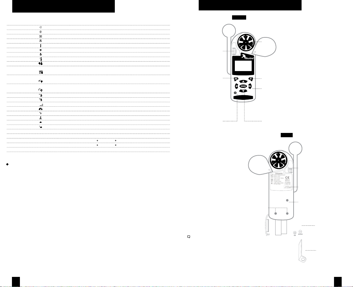
GETT ING TO KNOW YOUR KESTREL
FRONT
BLACK GLOBE SENSOR
HUMIDITY
SENSOR
MANUAL MEMORY
BUTTON
POWER / SETUP
BUTTON
Figure 2
Figure 1
REPLACEABLE
IMPELLER
BACKLIGHT
BUTTON
NAVIGATION
BUTTONS
SELECT / EXIT
BUTTON
BACK
AMBIENT
TEMPERATURE
SENSOR
DATA UPLOAD
OPTICAL COUPLER
Even when the Kestrel display is o, the unit will still
automatically collect and store data at the dened rate
(see “Memory Options” ). To completely power down
the unit, you must remove the batteries, which will
cause time, date and user settings to be lost.
SERIAL NUMBER
PRESSURE SENSOR
CAUTION - DO NOT
POKE!
AAA BATTERIES (2)
STABILIZING BATTERY
ORIENTATION SHIM
Kestrel 4600 Only
54
Page 4
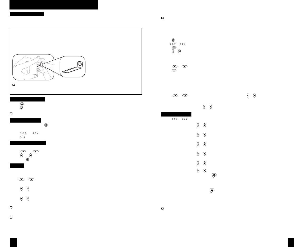
GETT ING STARTED
Battery Installation
• Insert batteries into bottom of Kestrel unit as shown on battery door.
• Snap door closed.
KESTREL 4600:
AAA batteries have a magnetic signature strong enough to aect the Kestrel compass
readings. Please follow this extra step to ensure the batteries stay in proper orientation.
Before closing the door, push the plastic shim (provided with unit) between batteries
and place clear ring on end over positive battery “bump.”
Figure 1
When replacing batteries in the Kestrel 4600, always keep the shim and re-insert with new
batteries as described.
Turning ON and OFF
• Press
to turn on the meter.
• Hold
for 3 seconds to turn o the meter.
You can also select “O” on the Main Setup Menu options.
Main Setup Menu
• When unit is on, press
customize preferences.
• Press
• Press
and to scroll through the options.
to select the highlighted option.
to access the Main Setup Menu which is used to
Date and Time Setup
• After battery installation, the meter will automatically enter the Date and Time Setting mode.
• Press
• Press
• Press the
and to scroll to each option.
and to adjust each option.
button to exit to the Main Setup Menu.
System
Contrast, auto shutdown, and calibrations can be
recongured as needed in the System screen.
or to highlight one of the following options:
• Use
Contrast
or to increase or decrease the display contrast from 0 (lightest) to 20 (darkest).
• Press
Auto Shutdown
or to set the time at which the display will automatically shut o after non-use
• Press
(choose 15 min, 60 min, or O to de-activate auto shutdown).
Battery life will be shortened if the Auto Shutdown is turned to “O.”
Baro Cal
Recalibration of this sensor is not recommended without speaking to an NK technician. See “Barometric
Pressure & Altitude Setup” section on page 10 for calibration instructions.
Humidity Cal
Recalibration of this sensor is not recommended without speaking to an NK technician. Full humidity
calibration instructions are provided with the Kestrel RH Calibration Kits. The unit may also be returned to
NK for calibration.
Visit www.nkhome.com for more information.
Date & Time
to enter the Main Setup Menu.
• Press
• Use
or to highlight Date & Time.
to enter the Date & Time Screen.
• Press
or to change each value.
• Press
Language
Display text can be set to 1 of 5 languages: English, French, German, Italian, and Spanish.
• Press
• Press
or to scroll the desired language.
to select the highlighted language.
Restore
This menu contains options for global settings of all units to metric or imperial, and
returning the reference values for the Alt and Baro screens to default (0 ft, 29.92 inHg).
To change units:
• Press or to scroll to the desired setting and press or .
To return the reference values for the Baro and Alt screens to default:
• Scroll to Defaults and press
or .
Memory Options
• Press
Clear Log Go Press
or to scroll to one of these options:
or to clear stored data
(will also clear Min/Max/Avg log).
Reset MMA Go Press
Auto Store On Press
Store Rate* 1hr Press
Overwrite On Press
Man Store On Press
* When unit is o, data will continue to be stored unless the 2 sec or 5 sec Store Rates have been selected.
or to clear Min/Max/Avg data
(Chart data will remain intact).
or to turn “On” (data will automatically store at Store Rate) or
“O” (data will only store when manually captured with the button).
or to increase or decrease frequency at which data is stored
(from 2 sec - 12 hr).
or to turn “On” (will discard oldest data point to capture new
data when log is full) or “O” (will not capture new data when log is full).
or to turn “On” or “O”
(O will disable
button).
Data Storage
To manually store data, press the
• Data Stored: veries that data was captured and will appear on chart.
• Full: indicates overwrite is o and data log is full.
• O: indicates that the Manual Store button has been disabled.
See Main Setup Menu for more information on memory.
button. The screen will conrm data storage status.
76
Page 5
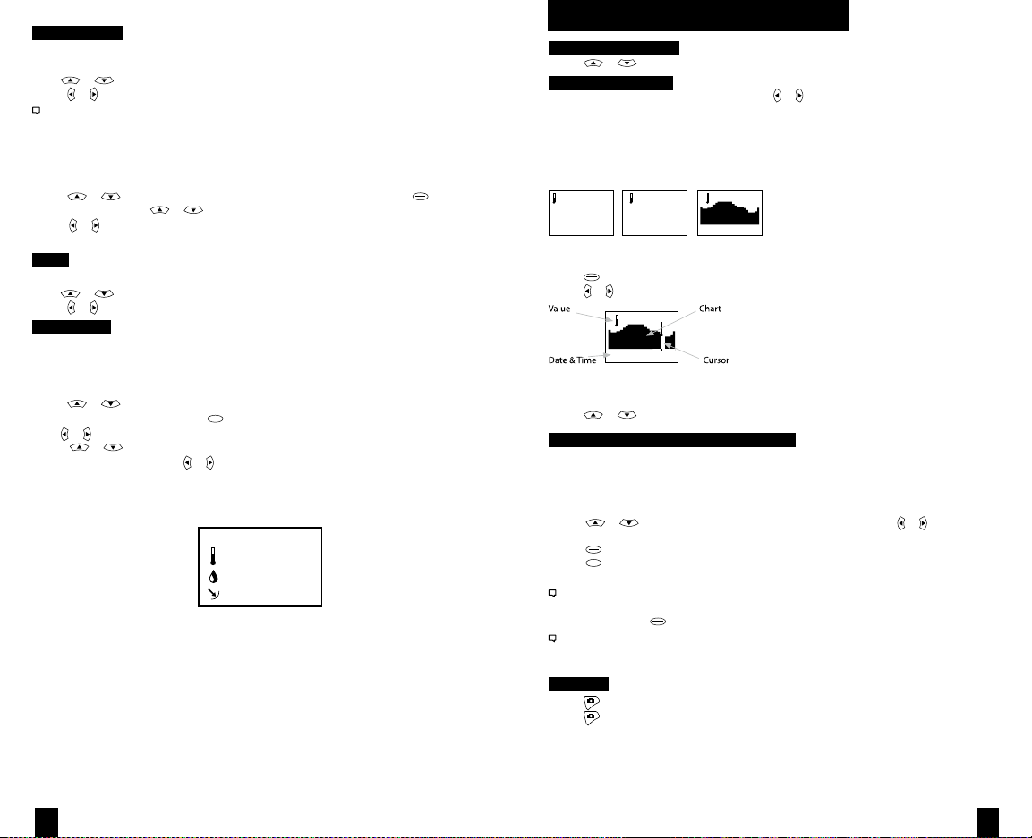
Measurements
Use this setup to “hide” unwanted Measurement screens from the normal Measurement
navigation.
or to scroll to the desired Measurement screen.
• Use
• Press
or to turn screen “On” and “O”.
The Kestrel Meter will continue to log data for hidden measurements. To view logged data of the hidden
measurement, go to Measurement setup, select the Measurement screen you want to view, and turn it back
“On.”
When the Kestrel is in Chart mode, the upper and lower limits of the graph scale may need
to be adjusted to fully view all data points. You can customize these value limits using the
Graph Scale setup.
• Press
• In the new screen, use
or to scroll to the Measurement you want to adjust, then press .
or to highlight “Set High” or “Set Low”.
• Press or to adjust the value limit of your
chosen option.
Units
This setup option lets you select units of measure to best suit your application.
or to scroll to each measurement.
• Use
• Press
or to change the unit of measurement.
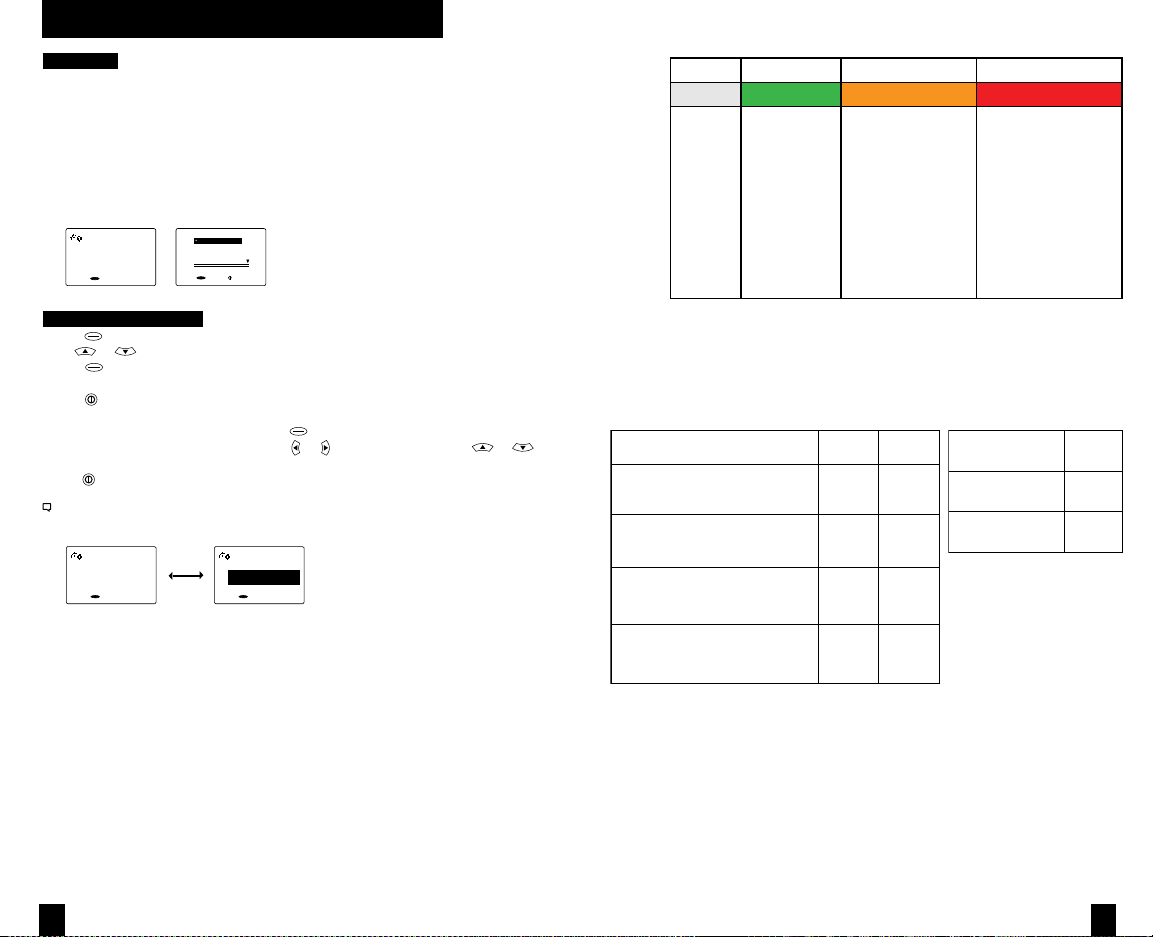
User Screens
The Kestrel allows you to set up to 3 customized User Screens that will display 3 current
Measurement values on the same screen. These screens are helpful for quick reference if
you need to monitor multiple measurements at once. The User Screen option allows you to
customize your user screens.
• Press
or to highlight .
User Screen 1, 2 or 3, then press .
• Use or to set your preferred measurement option.
• Press
or to highlight
the remaining lines, and use or to set those Measurement options.
Repeat these steps to set up the other User Screens.
When accessed through the Measurement navigation, each User Screen will display current data for the chosen measurements as programmed.
User Screen 2
22.5 °F
Figure 1
48.6 %
1014.6 inHg
Sample User Screen
SCREEN NAVIGATION
Measurement Screens
• Press
or to scroll through the Measurement screens.
Measurement Modes
• From your chosen Measurement screen, use
Current: Displays instantaneous reading.
Min/Max/Avg: Displays the Minimum, Maximum, and Average readings from stored data
(Displays --.- if no data has been stored).
Chart: Displays graph of stored data points for each measurement.
Current Min/Max/Avg Chart
TEMPF
76.4
TEMPF
Min32.4
Avg67.9
Max84.0
TEMPF
—fordata
or to scroll through the Mode options:
Figure 1
To View Chart Data:
while viewing a chart. A cursor will appear on the most recent data point.
• Press
• Press
or to scroll through saved data:
56.0F
Figure 2
Feb2716:58:14
The data value will be displayed at the top of the screen. The date and time when
each data point was stored will be displayed at the bottom of the screen.
• Press
or to review the chart data for other measurements.
MAX/AVG FUNCTIONS -
Wind Speed & Wind Chill
These values are measured independently from stored and charted data to allow the
user to start and stop the averaging period in the manner most appropriate for their
application. Averaging on all wind-related values will be started and stopped together.
To measure these values:
• Press
• Press
• Press
or to scroll to a wind measurement screen, then use or to
select Min/Max/Avg screen.
to begin collecting data.
again to stop data collection and display the Maximum and Average
values.
This routine will work simultaneously for both measurements, regardless of which one is displayed
when run. No other Min/Max/Avg or stored data will be aected.
• To clear data, press when the screen says “— clear”.
Other measurements will display min / max / avg data based on the data stored in the log (using either
auto-stored or manually captured data). This data can be cleared by using “Reset MMA” under
memory options.
Backlight
to activate backlight for one minute.
• Press
• Press
again to deactivate the light manually.
98
Page 6

MEASURING HEAT STRESS
The Kestrel Heat Stress Trackers will only yield accurate measurements using the
following guidelines. It is important that the meter be fully acclimated to the
measurement environment for accurate readings.
Proper Placement
The Kestrel Heat Stress Trackers should always be used at least 3 feet from the ground. If the unit is laid
on the ground, it will compromise the measurements of user’s conditions. To ensure proper placement,
use the Kestrel Vane Mount (included) and Compact Collapsible Tripod.
Optimal Acclimating Time
If taken from a cool environment, where the Kestrel Heat Stress Tracker was stored, to an outside heat
stress climate, the unit will need to adjust accordingly. Give the unit a minimum of 7 minutes to adjust
to the outside climate if taken from storage (examples: air conditioned building, car glove box, truck
gearbox, etc). 10 minutes of acclimation time is recommended. If worn on the person without the Black
Globe exposed, the meter will need at least 2 minutes to display accurate measurements (examples:
jeans pocket, shirt pocket, etc).
Repeat Measurements
When transporting the unit with the intention of taking repeat measurements, such as on a hike
or march, try to keep the unit exposed as much as possible. A Kestrel Belt-Clip Carry Pouch or
MOLLE-Compatible Tactical Carry Pouch is ideal for this purpose as the Black Globe sensor remains
exposed to the air.
Note: Please read the cautions and warnings on page 2 of the manual carefully. Consider all relevant
factors, such as amount of work being completed, distance traveled with respect to people or animals, or
clothing worn when making judgments on heat stress.
WET BULB GLOBE TEMPERATURE
Measuring
The unit will calculate and display Wet Bulb Globe Temperature based on Globe
Temperature, Relative Humidity, Ambient Temperature, Barometric Pressure,
and Wind Speed.
WBGT in F
73.2
settings
Figure 1
To Change WBGT settings:
• Press
while on the Wet Bulb Globe Temperature screen.
• Use
or to change the “Type” setting between outdoor and indoor, (see glossary for
more info).
• Use
to scroll to “App”, then use or to change the Application.
to exit the WBGT settings screen.
• Press
Note: Warning zones for WBGT are listed in gure 1 (page 12). If red or black warnings are displayed, the
number will ash to alert the user with the screen name contrast inverting. Unless the screen says “None”,
the ag color will ash. See below screenshots for examples of inverting screen contrast. For information on
work/rest ratios and water consumption, refer to Figure 1.
WBGT in
F
86.2
Warning: Black
settings
WBGT in
F
86.2
Warning: Black
settings
Figure 2
SIX USER-SETTABLE WARNING ZONES
The Kestrel Heat Stress Trackers allow you to customize the settings of your heat-related
warning zones based on your specic needs.
No risk
Low risk
Moderate risk
Moderate risk
High risk
Extreme risk
Your Kestrel Heat Stress Tracker allows you to activate and set up
to six customized heat stress warning zone thresholds to trigger
warnings identied by color names on screen. The warnings
are in increasing order of severity of risk of heat injury as shown.
Figure 3
ES
SET OUTDOOR/INDOOR MODE AND TURN ON THE WARNING ZONES
• Navigate to the WBGT Screen.
• Press
• Use
• Use
to enter the Settings Screen.
or to change the “Type” setting between outdoor and indoor.
to highlight “Warnings,” then use or to turn on or o.
TO SET WBGT WARNING ZONES
• Press
• Use
• Use
• Press
• On the selected warning zone screen, press
• Press
while on the WBGT Screen.
to highlight “Warning setup” and press .
or to scroll to dierent warnings zones identied by color names.
to enter the selected warning zone.
to turn the “Warning” on or o.
to highlight “Temp.” Use or to adjust the temperature value. Refer to the
“WBGT Reference Guidelines” on the reverse side of this insert for suggested settings.
When a warning zone is turned “On,” the WBGT screen will display the appropriate
warning color (i.e. Warning: White) related to the specied temperature.
Note: The Red Warning Zone is further identied by a reverse ash of the warning. The Black Warning
Zone will reverse ash the WBGT value to alert the user. See below screenshots for examples of the screen
reverse ash.
WARNING
The following WBGT Reference Guidance Charts are summarized from well-regarded
published papers, policies and position statements relating to preventing heat injury.
These guidelines are provided for reference only and do not constitute medical advice.
These guidelines, and your Kestrel Heat Stress Tracker, must be employed with care and
good judgment. Please remember that certain individuals are more susceptible to
exertional heat stress and the Kestrel Heat Stress Trackers are environmental meters,
not medical devices. For more information on heat stress injury prevention, visit
HeatStress.com.
When in doubt, set your Zone Thresholds lower, reduce work time and increase rest
and hydration.
1110
Page 7

Figure 4
Work/Rest and Water Consumption Table
Applies to average sized, heat-acclimated soldier wearing BDU, hot weather. (See TB MED 507 for further guidance.)
Easy Work Moderate Work Hard Work
• Weapon Maintenance
• Walking Hard Surface at 2.5 mph,
< 30 lb Load
• Marksmanship Training
• Drill and Ceremony
• Manual of Arms
Heat
WBGT
Category
Index, Fº
1 78º - 81.9º NL ½ NL ¾ 40/20 min ¾
2
82º - 84.9º NL ½ 50/10 min ¾ 30/30 min 1
GREEN)
(
3
85º - 87.9º NL ¾ 40/20 min ¾ 30/ 30 min 1
YELLOW)
(
4
88º - 89.9º NL ¾ 30/30 min ¾ 20/40 min 1
RED)
(
5
> 90º 50/10 min 1 20/40 min 1 10/50 min 1
BLACK)
(
For additional copies, contact: U.S. Army Center for Health Promotion and Preventive Medicine Health Information Operations Division
at (800) 222-9698 or CHPPM - Health Information Operations@apg.amedd.army. mil.
For electronic versions, see http://chppm-www.apgea.army.mil/heat. Local reproduction is authorized.
June 2004 CP-033-0404
Figure 4: Work/Rest ratios and Water Consumption Guidelines. (Source: U.S. Army Center for Health
Promotion and Preventive Medicine Health Information Operations Division.
URL: http://safety.ucanr.org/les/2091.pdf)
For additional copies, contact: U.S. Army Center for Health Promotion and Preventive Medicine Health Information Operations Division at (800)
222-9698 or CHPPM - Health Information Operations@apg.amedd.army. mil. For electronic versions, see http://chppm-www.apgea.army.mil/heat.
Local reproduction is authorized. June 2004
• Walking Loose Sand at 2.5 mph,
No Load
• Walking Hard Surface at 3.5 mph,
< 40 lb Load
• Calisthenics
• Patrolling
• Individual Movement Techniques,
i.e., Low Crawl or High Crawl
• Defensive Position Construction
Easy Work Moderate Work Hard Work
Water
Work/Rest
Intake
(min)
(qt/hr)
Work/Rest
(min)
• Walking Hard Surface at 3.5 mph,
≥ 40 lb Load
• Walking Loose Sand at 2.5 mph
with Load
• Field Assaults
Water
Work/Rest
Intake
(min)
(qt/hr)
• The work/rest times and fluid
replacement volumes will sustain
performance and hydration for
at least 4 hrs of work in the
specified heat category. Fluid
needs can vary based on
individual differences (± ¼ qt/hr)
and exposure to full sun or full
shade (± ¼ qt/hr).
• NL = no limit to work time per hr.
• Rest = minimal physical activity
(sitting or standing) accomplished
in shade if possible.
• CAUTION: Hourly fluid intake
Water
should not exceed 1½ qts.
Intake
(qt/hr)
Daily fluid intake should not
exceed 12 qts.
• If wearing body armor, add 5°F to
WBGT index in humid climates.
• If doing Easy Work and wearing
NBC (MOPP 4) clothing, add
10°F to WBGT index.
• If doing Moderate or Hard Work
and wearing NBC (MOPP 4)
clothing, add 20°F to WBGT
index.
Figure 5
GUIDANCE FOR HIGH SCHOOL A THLETICS
WBGT READI NG
UNDER 82.0
82.0 - 86. 9
87.0 - 89. 9
90.0 - 92. 0
OVER 92
GHSA Heat Index Record Sheet. Georgia High School Athletic Association Heat Index Measurement and Record. 2012:1.
ACTIVITY GU IDELINES & R EST BREAK G UIDELINES
Normal activ ities - Provide at least three separate rest br eaks
each hour of minimum duration of 3 m inutes each during work out.
Use discreti on for intense or prolon ged exercise; watch at- risk players
carefully; P rovide at least three se parate rest breaks each hour of a
minimum of f our minutes duration eac h.
Maximum prac tice time is two hours! For football: players r estricted to
helmet, shou lder pads and shorts dur ing practice. All prote ctive
equipment mu st be removed for condit ioning activities. For all sports:
Provide at l east four separate rest breaks each hour of a m inimum of
four minutes each.
Maximum leng th of practice is one ho ur, no protective equip ment may
be worn duri ng practice and there ma y be no conditioning ac tivities.
There must b e 20 minutes of rest bre aks provided during the
hour of prac tice.
NO OUTDOOR W ORKOUTS! Cancel exercise ; delay practice until
a cooler WBG T reading occurs.
Figure 6
GUIDANCE FOR ATHL ETIC TRAI NERS
WBGT
o
<18 C (<65 F )
o
18-23 C (65- 73 F)
o
23-28 C (73- 82 F)
o
>28 C (82 F)
Roberts WO. Medical management and administration manual for long distance road racing. In: Brown CH, Gudjonsson B, eds. IAAF
Medical Manual for Athletics and Road Racing Competitions: A Practical Guide. Monaco: International Amateur Athletic Federation
Publications; 1998:39–75.
FLAG
COLOR
o
Green
o
Yellow
o
Red
o
Black
LEVEL OF
RISK
Low
Moderate
High
Extreme or
Hazardous
COMMENTS
Risk low but still exists on the bas is
of risk fact ors.
Risk level i ncreases as event
progresses t hrough the day.
Everyone sho uld be aware of injury
potential; i ndividuals at risk shoul d
not compete.
Consider res cheduling or delaying th e
event until safer conditions prevail ; if the
event must t ake place, be on high al ert.
Figure 7
GUIDANCE FOR CHIL DREN’S SP ORTS PRAC TICE
Guidance for heat-acclimated soldiers
MODIFYING P RACTICE SESS IONS FOR EX ERCISING CH ILDREN
WBGT
o
F C
o
<75.0 <24.0
75.0-78.6 24.0-25.9
79.0-84.0 26.0-29.0
>85.0 >29.0
Notes:
1. Source: refer ence (7).
2. These guideli nes do not account for clothing. Although the effects of the uniform clothing and protective equipment
(i.e., Ameri can football) on sweati ng and body temperature in younger athletes ar e unknown, uniforms sho uld be considered
when determi ning playing/practice l imitations based on the WBGT.
3. Eight to 10 p ractices are recommende d for heat acclimatizat ion (30–45 min each; on e per day or one every other day).
4. Differences o f local climate and ind ividual heat acclimatiz ation status may allow activity at higher leve ls than outlined in the
table, but a thletes and coaches sho uld consult with sports medicine staff and sho uld be cautious when ex ceeding these limits.
American Academy of Pediatrics. Climatic heat stress and the exercising child and adolescent. Pediatrics 106(1):158–159, 2000.
RESTRAINTS ON ACTIVITIE S
All activiti es allowed, but be alert for the prodromes of h eat-related
illness in p rolonged events.
Longer rest periods in the shade; en force drinking every 15 min.
Stop activit y of unacclimatized pers ons and high-risk perso ns; limit
activities o f all others (disallow l ong-distance races, cut the duration
of other act ivities.
Cancel all a thletic activities.
In addition to utilizing the guidance that is applicable to your environment
and/or event, please refer to YOUR SPECIFIC STATE’S REQUIREMENTS for
measuring WBGT and heat acclimatization guidelines.
Figure 8
ISO 7243 T HRESHOLD L IMIT VALU ES FOR WOR K ENVIROME NTS
WORK-REST
REGIMEN
Continuous wo rk
75% work + 25 % rest; each hour
50% work + 50 % rest; each hour
25% work + 75 % rest; each hour
Parsons, Ken. Heat Stress Standard ISO 7243 and its Global Application. Industrial Health 2006(44):368-379.
LIGHT
o
C F
30.0
30.6
31.4
32.2
WORK LOAD
MODERATE HEAVY
o
o
C F
86.0
26.7
87.1
28.0
88.5
29.4
90.0
31.1
80.1
82.4
84.9
88.0
o
C F
25.0
25.9
27.9
30.0
77.0
78.6
82.2
86.0
o
o
1312
Page 8
THERMAL WORK LI MIT TWL 4400 ONLY
Measuring
The unit will also display a measure of human heat stress known as “Thermal Work Limit,”
or “TWL.” TWL is based upon Globe Temperature, Relative Humidity, Ambient Temperature,
Barometric Pressure, Wind Speed, and parameters specic to the population using the
Thermal Work Limit measurement. These parameters are the Intrinsic Clothing Insulation
Factor (IClo), Vapor Permeation Factor (VPF), Position of the body (Pos), and surface area of
the person (Area). See Clothing Ensemble Level Setting Screen below. TWL is measured in
terms of the heat energy a person can dissipate from their surface area in Watts per square
meter (w/m2). TWL incorporates recommended acclimitization, buer and withdrawal
zones as depicted in the following chart (page 16).
TWL
245.7
Unrestricted
settings
ShSlv/Shorts
ShSlv/Pants
Coveralls
Business suit
ShSlv/Shorts
select exit
Figure 1
2
w/m
To Change TWL settings:
while on the Thermal Work Limit screen.
• Press
• Use
or to scroll to dierent ensembles.
to select the desired ensemble.
• Press
• A bullet indicates the selected ensemble.
to exit the WBGT settings screen.
• Press
• If Custom is selected, each factor specic to the user can be altered (shown above).
• To view the specics of an ensemble, press
• If viewing the Custom ensemble specs, use
to scroll to dierent parameters.
to exit the ensemble specs, and once more to exit TWL settings screen.
• Press
Note: “Acclim” will blink on the TWL screen when the meter detects that Acclimatization is the current zone.
In the Buer or Withdrawal zones, the number will ash as shown in the screenshots below. For information on
TWL interventions, refer to Figure 2. For typical numeric values for each factor, refer to Figure 3.
TWL
112.7
Withdrawl
settings
2
w/m
TWL
112.7
Withdrawl
settings
after selecting it.
or to adjust each value, and or
2
w/m
Figure 2
2
TWL (w/m )
Working Zone
Interventions
*Unacclimatized workers are dened as new workers who have been o work for more than 14 days due to
illness or leave (outside the tropics).
Figure 3: TWL values, working zones, and interventions.Source: Health Authority, Abu Dhabi.
URL: http://haad-safe.ae/index.php?option=com_content&view=article&id=27&Itemid=50
ENSEMBLE
Men’s business suit: Long sleeve shirt/
tweed suit jacket & long, loose trousers
Short sleeve shirt/denim shorts
Work Clothes: Short sleeve shirt/long
trousers (denim)
Work Clothes & Coveralls
> 220 140-220 115-140 < 115
Unrestricted
No limits on
self-paced
work for trained,
hydrated workers.
Acclimatization
No restriction for
acclimatized workers
Workers with uncertain
acclimatization status
should not work alone
in this zone
• Be aware of increased
risk of heat illness
• Dehydration test for
rst two shifts back
from leave
Buer Withdrawal
Buer zone exists to identify situations
in which environmental conditions
may be limiting to work
• Any practicable intervention to reduce
heat stress should be implemented e.g.
provide shade, improve ventilation etc
• Working alone to be avoided if possible
• Unacclimatized* workers not to work in
this zone
• Use the technical information
sheets ‘Work-rest cycling – sample
schedules’ and ‘Fluid requirements for
working in heat’ to prescribe maximum
exposure time, work/rest cycling and
uid intakes appropriate for type of
work and conditions
IClo
1.13
0.41
0.50
0.96
VPF
0.37
0.43
Figure 4: (left/above) Typical values for IClo,
VPF, and POS. Typical value for Area of a man
is 1.7. Sources: “Heat and Moisture Transfer
0.40
Through Clothing” (http://www.ibpsa.org/
proceedings/BS2009/BS09_1360_1366.pdf),
and “A Comprehensive Database for Estimating
Clothing Insulation,” Institute for Environmental
Research, Kansas State University; Elizabeth
McCullough and Byron James.
0.39
Work limited to essential maintenance
or rescue operations
• No person to work alone
• No unacclimatized* person to work
• Documentation required authorising
work in hostile thermal conditions for
specic purpose
• Specic induction required emphasizing
hydration and identifying signs of
heat strain
• Apply 20 minutes of work – 40 minutes
rest schedule
• Required uid intake exceeds 600 ML
per 30 minutes
• Personal water bottle (2 liter capacity)
must be on the job at all times
• Mandatory dehydration testing at
end of shift
POSITION
Lying down
Standing up
VALUE
0.00
1.00
1514
Page 9

BLUETOOTH® SETUP
BLUETOOTH SETUP
(BLUETOOTH ENABLED METERS ONLY)
To transfer your Kestrel’s real-time and logged data
wirelessly and automatically to a laptop or PDA, follow
these set up steps.
Enable the Kestrel’s BLUETOOTH Capability
to enter the Main Menu.
• Press
• Use
or to highlight “Bluetooth,” then press .
• Use
or to change from “O/Disabled” to “On/Ready”.
Set BLUETOOTH Range
In Bluetooth screen:
• Use or to highlight “Range”.
• Use
and adjust the range to “Low” (3ft), “Medium” (10ft), or “High” (30ft).
Obtain your Kestrel BLUETOOTH PIN and ID
For added security, each Kestrel comes with a unique PIN and ID number to ensure
proper pairing.
In the Bluetooth screen:
to highlight “Info,” then press to view your unique ID and PIN.
• Use
Pair Your Kestrel with Your Computer
First, make sure your Kestrel unit’s Bluetooth is set to ON. Open the Bluetooth
management software on your computer and follow the prompts to enter the PIN.
A COM Port will be assigned and displayed in the software once connection to the
Kestrel is established.*
This is a general guideline for pairing your Kestrel with your computer. Individual Bluetooth software
programs and navigation may vary, and some computers do not come equipped with Bluetooth
capability and will need additional products to communicate via Bluetooth.
* A “Bluetooth Error” screen will appear on the Kestrel if pairing
is unsuccessful.
Set Up Kestrel Communicator Software
• Go to: http://www.nkhome.com/kestrel/software.
• Download and install the Kestrel Communicator Software from this link.
• Once installed, the “Kestrel Communicator” icon will appear on your desktop.
Click on the icon and use the “Help” tab to nd full instructions for use.
BAROME TRIC PRESSU RE & ALTITUDE SETUP
Setting Barometric Pressure & Altitude
The Kestrel meter measures “station pressure”, which changes in response to both changes
in altitude and changes in atmosphere. Barometric pressure is a measurement of the
air pressure adjusted to sea level. To obtain accurate barometric pressure and altitude
readings, you must rst know EITHER your location’s current barometric pressure OR your
current altitude.
Station pressure is displayed if the reference altitude is set to zero.
Be sure to adjust your reference measurements for altitude and/or barometric pressure when you change
your location or when there have been dramatic changes in weather conditions.
OPTION 1
Start with Known Altitude for your Location
or to scroll to highlight the “BARO” screen
• Use
• Press
to enter the “REF BARO” screen
Baro Displays current Barometric Pressure
Ref Alt Use
Sync Alt Use
to set the known Altitude
or
to switch “On” and sync the Baro reading to the “Altitude” screen
or
When “Sync Alt” is turned “On,” the current Barometric
Pressure data is automatically used as a reference for
Altitude, and both screens will show accurate readings.
REFALT
Alt 877
Ref. Baro 30.97
Sync Baro On
adjust exit
syncs
REFBARO
Baro
Ref. Alt 877
Sync Alt
adjust exit
Figure 1
OPTION 2
Start with Known Barometric Pressure
for your Location
or to highlight the “Altitude” screen
• Use
• Press to enter the “REF ALT” screen
When “Sync Baro” is turned “On,” the current Altitude data is automatically used as a
reference for Barometric Pressure, and both screens will show accurate readings.
REFBARO
Baro 30.15
Ref. Alt 115
Sync Alt On
adjust exit
“Density Altitude” screen data is calculated from the absolute values of station pressure, relative humidity
and temp., and is not aected by the reference values entered in the “Baro” and “Altitude” screens.
syncs
REFALT
Alt
Ref. Baro 30.15
Sync Baro
adjust exit
Figure 2
1716
Page 10

IMPELLER REPLACEMENT
COMPASS CALIBRATION 4600 ONLY
Replacing the Kestrel impeller
Press only the sides of the impeller when removing and inserting to avoid damaging the precision
hub bearing. (Figure 1) .
• Press FIRMLY on the impeller module to remove it.
• Insert the new impeller so the side that has the small triangle (close to the perimeter)
faces the front of the Kestrel when installed. Orient one “arm” of the module straight up .
(
Figure 2). The impeller can be pushed in from either side.
Figure 1
In addition to Wind Speed and Wind Chill, the Kestrel 4600 also measures Direction,
Headwind/Tailwind and Crosswind.
Digital Compass Calibration
The digital compass must be calibrated to correct for the AAA batteries’ magnetic eld. It must be
re-calibrated every time the battery door is opened, and it will not display or log any direction values until
calibration is complete.
**Impeller should be removed during calibration for best results.
• Remove the impeller by pressing the edges to pop it out (reinsert after calibration
is complete).
• Place the Kestrel meter in the foam stand provided so it remains balanced and vertical
[
Figure 1
]. You may also hold the Kestrel meter vertically in your hand and turn
your body.
To Calibrate:
• In Main Setup Menu, use
• Press
to highlight “Compass Cal”, then press .
Follow the prompts on screen:
• Press
to start.
• Slowly spin the upright meter around three (3) full times.
• Each rotation should take approximately 10 seconds.
• When calibration is nished, the screen will read “Cal Complete”.
• Press
to exit to Main Menu.
or to highlight “System”, then press .
To verify the digital compass’ accuracy, test it against a compass; the Kestrel meter
readings should be within ±5° of the reference compass or better. If readings appear
incorrect, simply run the calibration routine again.
Calibration Error Messages
There are three error messages that the meter may display during calibration. Press
to exit the error screen and run the calibration again.
• Magnetic Batteries: The magnetic eld of the Kestrel’s batteries is interfering with calibration. Simply open the battery door, rotate one or both batteries, and run the calibration
again.
• Too Slow: The unit was spun too slowly during calibration.
• Too Fast: The unit was spun too quickly during calibration.
Figure 2
Kestrel
Figure 1
3x
1918
Page 11

Measuring Direction
The Kestrel 4600's digital compass must be vertical to achieve accurate readings. Keep the unit positioned
as close to vertical as possible when using any compass-related feature. After opening the battery door,
you must re-run the calibration routine or readings will not register. For maximum accuracy, the impeller
should be spinning while measuring to eliminate its magnetic pull.
True North vs. Magnetic North Readings
The Kestrel 4600 default Direction display mode is Magnetic North. To view Direction in
True North mode:
• In the Direction screen, press
• Use
or to choose your mode.
• If you choose True North, use
Variation for your location.
.
to highlight “Variation”, then use or to input the
To measure Direction:
• Hold the unit vertically and point the BACK of the unit toward the direction you want
to measure.
• The unit will display the cardinal direction and degrees.
The Direction measurement does not record Max and Average and will display N/A on that mode screen.
Measuring Headwind/Tailwind & Crosswind
The Kestrel 4600 automatically calculates Headwind and Crosswind with respect to
a runway or target direction. You must rst set the “Heading” to view these measurements:
while on the Headwind or Crosswind screen.
• Press
• Use
or to choose “Auto Set” or “Manual Set”, then press .
In Auto Set: Point the unit down the runway or target, then press to automatically set the heading.
In Manual Set: Use
Both screens will always display the Magnetic North heading at the top (even if the Direction screen is
set to True North mode).
• After setting the heading, scroll to the desired parameter and orient the Kestrel so the
wind blows directly through the impeller.
or to enter the known runway or target heading, and press
to save.
VANE MOUNT ASSE MBLY
Assembling the Vane Mount
The Kestrel Vane Mount allows you to mount your Kestrel on any 1/4-20 equipped tripod for
long-term condition monitoring. The Vane Mount will keep your Kestrel correctly oriented into the
wind to fully capture relevent conditions.
The Vane Mount is designed for extreme light weight and portability, and assembles in seconds.
The Portable Vane Mount contains four components: a zippered carry pouch, a cup bracket with
incorporated level, a boom and a ight.
Step 1
Assemble the boom. Unfold the two pieces and stretch the bungee
gently, then slide the two pieces together (like a tent pole).
Step 2
Attach the ight to the at end of the boom. Grasp the silver bungee end AND the transparent bungee washer, then pull the bungee
out about 1/2 an inch. Drop the bungee into the slot in the center of
the ight while slipping the boom end into the opening in the center
of the ight.
Step 3
The assembled ight and boom looks like this.
Step 4
Attach the boom to the cup bracket. Locate the arrow on the inside
of the cup bracket base. Insert the boom end in the direction of the
arrow, all the way through the base of the vane mount. Grasp the silver
bungee end AND the small bungee washer, then pull the boom back,
stretching the bungee. Drop the bungee into the slot and slip the boom
end into the opening near the compass. Gently rotate the boom until
the angled end “seats” into the base of the opening.
Step 5
Attach the Vane Mount to your tripod and level your tripod. Spin the
Vane Mount knob onto the 1/4-20 mount on your tripod. Slip your
Kestrel into the Vane Mount with the display facing the bubble level
and the back side of the Kestrel facing the ight and boom. Adjust the
ight so it is vertical. Observing the level on the Vane Mount, fairly
adjust your tripod so the Vane Mount is level and rotates freely
and evenly.
2120
Page 12

DATA LOGGING AND MIN/MAX/AVERAGE
= 0.7 T + 0.2 T + 0.1 T
T = Naturally Aspirated Wet Bulb Temperature
Where =
When Autostore is on and the unit is o, the heat stress measurements will not be stored because they use
calculations that cannot be performed without power. When reviewing data in the graphical display, the
symbol “–“ will appear at the top of the display for any points not logged due to the above condition.
In wind-related measurements, a timer will appear at the bottom of the screen after starting the MMA
feature – this timer displays the elapsed time. Additionally, for each minute this feature is running a data
set will be stored in memory reecting the instantaneous conditions at that time. This will happen regard-
less of memory settings.
For additional information on memory options and logging data, please refer to the main
Kestrel 4000 series manual.
GLOSSARY
Globe Temperature
GLOBE TEMP
F
75.2
The Black Globe on the Kestrel Heat Stress Trackers is representative of the amount of heat-absorption
via the color black. Typically, Globe Temperature is taken using a 6” diameter copper globe painted black
with an internal thermometer. However, the Kestrel 4400 and 4600 use a 1” copper globe painted black
for calculations.
Globe Temperature is representative of the temperature of the Black Globe itself without accounting for
air temperature.
Naturally Aspirated Wet Bulb Temperature
WET BULB
F
58.5
Thermal Work Limit (TWL)
Like WBGT, TWL uses environmental measurements, including thermal radiation, to predict work
limits for people exposed to heat stress. Dierent attributes of clothing (such as its ability to insulate
and allow water vapor to pass through it) are also used to calculate TWL.
Acclimatization (Acclimatize)
Dened as the process of gradually adjusting to a change in environment (such as
a change in temperature, humidity, etc). During TWL mode “Acclim” will ash when
the value being displayed falls within the acclimitization zone. For example, people
who have not worked in such conditions should not be left alone until they have
acclimatized, a process requiring several days of gradually increased exposure to heat
stress conditions.
Black Globe
Typically a 6” copper sphere colored matte black with a thermometer in the center. This
thermometer reads the surface temperature of the Black Globe, which indicates the radiant heat exposure of one in sunlight. The Kestrel 4400 and 4600 Heat Stress Trackers
use a 1” Black Globe that is calibrated to achieve the same measurements as a 6” globe.
The Kestrel Heat Stress Trackers' Naturally Aspirated Wet Bulb Temperature function accounts for the
eects of humidity on the human body. By combining relative humidity and wind speed, the temperature
displayed is indicative of the evaporative cooling happening to the Kestrel 4400 or 4600.
Wet Bulb Globe Temperature (WBGT )
The WBGT is a composite measurement of Naturally Aspirated Wet Bulb, Globe Temperature & Dry Bulb
Temperature. This environment data combines temperature, humidity, wind speed and thermal radiation
to access heat stress.
Outdoor WBGT
G
NWB
D
Indoor WBGT
NWB
T = Globe Temperature
G
T = Dry Bulb Temperature
D
2322
Page 13

MAINTENANCE & SERVICE
Maintenance & Storage
To avoid scratching the window, store the Kestrel Heat Stress Tracker in the soft pouch
and/or use the Kestrel lens cleaning kit.
Software
To download the Kestrel Communicator software, visit:
www.nkhome.com/kestrel-software.
Calibrations, Certications & Service
Every NK product is tested and calibrated before it leaves our factory. We warrant that it
will perform within specications when you receive it. The unit may be returned to NK for
factory calibration, or you can contact NK for eld calibration instructions (RH Calibration
Kits are available on our website).
Each Kestrel Meter comes with a Certicate of Conformity, stating the specications for
that product.
If you are concerned your Kestrel is not performing within specications upon receipt,
please contact us and we will review your concerns. If necessary, we will test or recalibrate
any unit within 30 days of purchase.
Beyond 30 days, we oer reasonably-priced tests, calibration services, NIST-traceable
calibrations, and full Kestrel Meter tune-ups.
We oer full factory service on every product we manufacture for as long as we make
the product (and as long after as component availability permits). If we cannot repair a
product, we will oer you a replacement under our Loyalty Discount (even for accidental
damage and misuse).
Please contact NK if you feel your product is not working properly. We can often solve
product issues by phone or e-mail, saving you the time and expense of returning the
unit. If we require the product to be returned, you can obtain a Return Authorization to
expedite the handling of your return.
Made in the USA
Your Kestrel Weather & Environmental Meter was
designed, developed and built in the USA by Nielsen-Kellerman Co. of US and
imported components. We are a lean manufacturing enterprise committed to
continuous improvement of our products, processes, people and partners.
We strive to conduct our business in a sustainable manner and minimize harm
to the environment by actively implementing company-wide plans to conserve
energy, reduce waste, and recycle.
BATTERY MAI NTENANCE
Batteries
Kestrel Weather & Environmental Meters require 2 AAA batteries. Average battery life is
300 hours based on typical use. Based on specic usage, Bluetooth®-enabled meters will
average less battery life.
When using the Kestrel meter in extremely cold weather, it is recommended to use lithium batteries for
optimal performance.
Kestrel Battery Recommendations- Avoiding Corrosion and Damage
Your Kestrel meter will safely operate on high-quality alkaline batteries, lithium batteries
or rechargeable NiMH batteries. Please follow these recommendations to select the
right battery for your use and avoid damage to your Kestrel meter.
· Lithium AAA batteries (such as Energizer® Advanced or Ultimate brands) are virtually
leak proof and provide up to 50% additional capacity in Bluetooth® equipped models
as well as improved cold weather performance. They are also 30% lighter than alkaline
batteries and provided extended cold temperature performance for data logging. We
recommend using lithium batteries for most Kestrel applications.
· Rechargeable NiMH batteries are an excellent option for high-drain applications,
such as extended use of the Bluetooth® data transmission features. Low self-discharge
NiMH batteries are a particularly good choice as they will hold their charge for months
and still be ready to go when you want to put your Kestrel to use. You can also bring a
supply of pre-charged batteries to the eld, and still have the option of recharging them
many times. Recommended options include Sanyo® eneloop® and Rayovac® Platinum
pre-charged rechargeable batteries.
· Alkaline batteries are a cost-eective option when you will be regularly changing or
inspecting the batteries, and can control storage conditions and duration. All alkaline batteries are prone to leaking potassium hydroxide, particularly as they near full discharge. As
batteries discharge, they release a small amount of hydrogen gas, which exerts pressure
inside the battery and may eventually rupture its seals. Once a leak has occurred, the
potassium hydroxide and carbon dioxide from the air form potassium carbonate crystals
that grow and follow along the metal electrodes to the circuit board, causing oxidation
of the circuit and components. Damage caused by leaking alkaline batteries is usually
irreversible, and is NOT covered under the Kestrel warranty. When choosing to install alkaline
batteries, follow these recommendations carefully to avoid corrosion damage:
• Use US-made, name-brand batteries wherever possible. Do not mix brands of batteries. Do not mix alkaline batteries with
other types (lithium or rechargeable).
• Do not mix batteries of dierent ages or usage – replace both batteries at the same time with new batteries that have not
reached their expiration date.
• Remove batteries for long-term storage (more than one month of non-use). Even when powered down, the Kestrel
continues to log data and slowly discharge the batteries.
• Change your batteries when below 20% capacity.
• Inspect your batteries regularly (at least once a month) and remove immediately if you notice ANY moisture or white crystal
line material at either end.
• Always store your Kestrel meter with batteries installed within the specied temperature limits: -22.0 °F to 140.0 °F | -30.0 °C
to 60.0 °C. Be particularly careful not to leave a Kestrel meter with batteries installed inside a hot car in the summer.
• CAUTION: If you notice you have a leaking alkaline battery, be careful not to touch it with your bare skin or allow it to come
in contact with your eyes as the leaking material is very caustic. Remove and dispose of both batteries. If possible, loosen
and vacuum out any white powder. DO NOT BLOW INTO THE COMPARTMENT TO REMOVE THE POWDER – it can cause
eye or skin damage and will be driven further inside the unit. You may attempt to use a cotton swab moistened with white
vinegar to clean the contacts and gently swab out the battery compartment. Do not exert any force against the contacts
inside the battery compartment or you may bend or break them. Allow the battery compartment to dry completely and
try installing fresh batteries. If your unit still does not power up, you may contract Kestrel Support to inquire about our
Customer Loyalty Trade-In Program, which provides a signicant discount toward a replacement Kestrel meter.
25
A24
Page 14
5YEAR L IMITED PRODUCT WARRANTY
5-YEAR LIMITED WARRANTY
Your Kestrel Heat Stress Tracker is warrantied to be free of defects in
materials and workmanship for a period of FIVE YEARS from the date of its
rst consumer purchase. NK will repair or replace any defective meter or
part when notied within the warranty period, and will return the meter
via domestic ground shipping or NK’s choice of method of international
shipping at no charge. The following are excluded from warranty coverage:
damage due to improper use or neglect (including corrosion); damage
caused by severe or excessive impact, crushing or mechanical harm;
modications or attempted repairs by someone other than an authorized
NK repair agent; impeller failure not caused by a manufacturing defect;
normal usage wear; and/or damage caused by failed or leaking batteries;
and accuracy issues resolvable by recalibration. If no warranty registration
or proof of purchase is provided, the warranty period will be measured from
the meter’s date of manufacture.
Except for the warranties set forth herein, NK disclaims all other warranties, expressed, implied or statutory, including, but not limited to,
the implied warranties of merchantability or tness for a particular
purpose. Any implied warranties that may be imposed by applicable
law are limited to the term of this warranty. In no event shall NK be
liable for any incidental, special or consequential damages, including,
but not limited to, loss of business, loss of prots, loss of data or use,
whether in an action in contract or tort or based on a warranty, arising
out of or in connection with the use or performance of an NK product,
even if NK has been advised of the possibility of such damages. You
agree that repair, and (upon availability) replacement, as applicable,
is your sole and exclusive remedy with respect to any breach of the NK
Limited Warranty set forth herein.
NOTES:
All product liability and warranty options are governed exclusively by the
laws of the Commonwealth of Pennsylvania.
2726
Page 15

NIELSEN-KELLERMAN
21 Creek Circle, Boothwyn, PA 19061
Phone: (610) 447-1555
Fax: (610) 447-1577
Web: NKhome.com
Email: info@NKhome.com
Kestrel® Weather & Environmental Meters are
designed and manufactured in the USA
This device complies with Part 15 of the FCC Rules. Operation is subject to the
following two conditions: (1) this device may not cause harmful interference, and
(2) this device must accept any interference received, including interference that
may cause undesired operation.
28
NK#xxxx_1_13.3.19
 Loading...