

Page 1
I NS TR UC TI ON M AN UA L
AVAILABLE WITH
Wireless Data Transfer
Page 2

Your Kestrel Ballistics Weather Meter is designed to provide accurate measurement
CAUTION
!
of current conditions only. Depending on your location and environment,
Rapid temperature and humidity changes (i.e., moving your meter from indoors to outdoors) may cause inaccurate readings of
temperature and humidity as well as all readings that rely on either of these values. Before relying on a Kestrel Ballistics Weather
Meter readings, use care to either a) force air ow over the sensors by waving or slinging your meter through the air; or b) wait
until your unit’s readings have stabilized, indicating it has equilibrated to its new environment.
To maximize the accuracy and reliability of your readings:
• Ensure that your Kestrel Ballistics Weather Meter is in good repair and within factory calibration.
• Take readings frequently and carefully according to the guidelines above.
• Allow your meter’s readings to stabilize after signicant changes in temperature or humidity (i.e., changing location
from indoors to outdoors).
• Allow a margin of safety for changing conditions and reading errors (2-3% of reading is recommended).
Use extra care and good judgment when referring to your Kestrel Ballistics Weather Meter to make
2
any decisions regarding safety, health or property protection.
conditions may change rapidly.
Page 3

OVERVI EW
Features & Options .............................................. 4
Getting to Know Your Kestrel ............................ 5
Battery Installation .............................................. 6
Compass Calibration and Setup ....................... 7
Barometric Pressure & Altitude Setup ............. 9
AB MODE
Basic Navigation and Getting Started .............10
Gun Selection .......................................................11
Gun Library & Information Screen ................... 12
Target Screen ........................................................15
Environment Screen............................................ 17
Range Card Screen ..............................................18
Ballistics Screen ................................................... 19
Calibration & Custom Drag Curves ...................19
Bluetooth Setup ................................................... 20
Quick Keys ............................................................. 21
*for BLUETOOTH®-enabled models ONLY
WEATHER MODE
Setup and Options .............................................. 22
Screen Navigation ...............................................25
Impeller Replacement ........................................ 26
Using the Bootloader ......................................... 27
Glossary of Terms.................................................28
Ballistic & Environmental Quick Ref ................. 29
Full Range Card Data Sample ............................ 31
Specications .......................................................33
Choosing & Using Batteries ............................... 35
Warranty ................................................................ 37
NK, manufacturer of Kestrel brand Ballistics Weather Meters
is available to answer questions and provide support.
Contact NK by phone: 610.447.1555; fax: 610.447.1577;
email: info@NKhome.com; or web: NKhome.com
3
Page 4

FEATURES & OPTIONS
Measurement/ Uni ts of Measure Icon 4500
Wind Dire ction (Cardinal Po ints, Degrees)
Wind Spe ed | Air Speed (mph | fp m | Bft | m/s | km/h | kt )
Crosswin d Calculation (mph | f pm | Bft | m/s | km/h | k t)
Headwin d | Ta ilwind (mph | fpm | Bf t | m/s | km/h | kt)
Temperatur e* (˚F | ˚C)
Wind Chill ( ˚F | ˚C)
Relative H umidity (Gpp | G/kg)
Heat Stress I ndex (˚F | ˚C)
Dewpoi nt Te mp (˚F | ˚C)
Wet Bulb Temp (˚F | ˚C)
Barome tric Pressure (inHg | hPA | psi | mb)
Altitud e, m | ft
Densit y Altitude, m | ft
Pressure Trend
Backli t Display
Data Stora ge Points 2900
BLUETOOTH ®
4
NV Backl ight
Standard • | Optional
w/Applied Ba llistics
.
.
.
.
.
.
.
.
.
.
.
.
.
.
.
.
Page 5

GETT ING TO KNOW YOUR KESTREL
FRONT
REPLACEABLE
HUMIDITY
SENSOR
MANUAL
MEMORY
BUTTON
POWER / SETUP
BUTTON
Even when the Kestrel display is o, the unit will still automati-
cally collect and store data at the dened rate (see “Memory
Options” ). To completely power down the unit, you must
remove the batteries (and lose time / date and other settings)
IMPELLER
BACKLIGHT
BUTTON
NAVIGATION
BUTTONS
SELECT / EXIT
BUTTON
DATA UPLOAD
OPTICAL COUPLER
* All Kestrel Meters with
temperature measurement
allow you to measure air,
water and snow temperature.
BACK
AMBIENT
TEMPERATURE
SENSOR
SERIAL NUMBER
WIDE RANGE
PRESSURE
SENSOR
AAA BATTERIES (2)
(Lithium recommended)
STABILIZING
BATTERY
ORIENTATION SHIM
5
Page 6
BATTERY INS TALLATION
• Insert batteries into bottom of
Kestrel unit as shown on battery
door.
• Snap door closed.
Turning ON an d OFF
to turn on the meter.
• Press
• Hold for 3 seconds to turn o
the meter.
You can also select “O” on th e
Main Setup M enu options.
Date & Tim e
to enter the Main Setup
• Press
Menu.
• Use
or to highlight Date
& Time.
• Press to enter the Date & Time
Screen.
or to change each value.
• Press
6
KESTREL 4500:
AAA batteries have a magnetic signature strong
enough to aect the Kestrel 4500’s compass
readings. Please follow this extra step to ensure
the batteries stay in proper orientation.
Before closing the door, push the plastic shim
(provided with unit) between batteries and place
clear ring on end over positive battery “bump.”
When replacing batteries in the Kestrel 4500, always keep
the shim and re-insert with new batteries as described.
Page 7

COMPASS CALIBRATION AND SETUP
In addition to Wind Speed and Wind Chill, the Kestrel
with Applied Ballistics Software also measures
Direction, Headwind/Tailwind and Crosswind.
Digit al Compass Cali bration
The Kestrel meter's digital compass must be calibrated
to correct for the AAA batteries’ magnetic eld. It must
be re-calibrated every time the battery door is opened,
and it will not display or log any direction values until
calibration is complete.
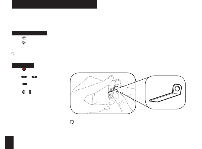
**Impeller should be removed during calibration for best
results.
• Remove the impeller by pressing the edges to pop it out
(reinsert after calibration is complete).
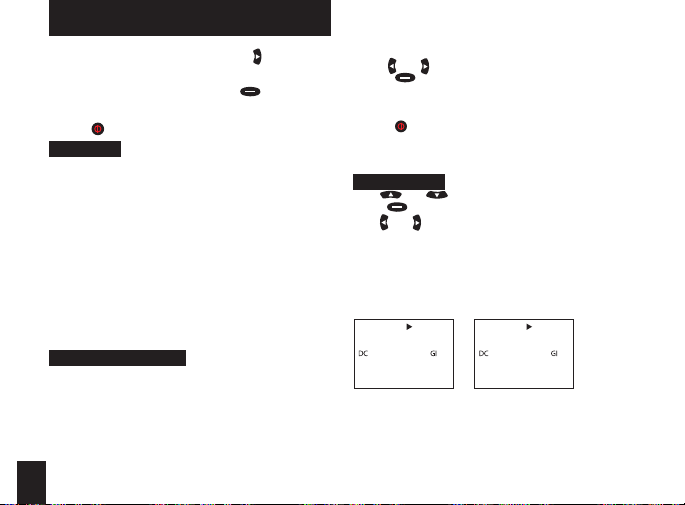
To Calibrate :
• In Main Setup Menu, use
“System”, then press
to highlight “Compass Cal”, then press .
• Press
Follow the prompts on screen:
to start.
• Press
• Slowly spin the upright meter around three (3) full times.
• Each rotation should take approximately 10 seconds.
• When calibration is nished, the screen will read
“Cal Complete”.
to exit to Main Menu.
• Press
To verify the digital compass’ accuracy, test it against a
or to highlight
.
compass; the Kestrel meter readings should be within
±5° of the reference compass or better. If readings appear
incorrect, simply run the calibration routine again.
Unit should be held vertically with the back facing the
direction being measured.
Calibr ation Error Me ssages
There are three error messages that the meter may
display during calibration. Press
screen and run the calibration again.
• Magnetic Batteries: The magnetic eld of the Kestrel’s
batteries is interfering with calibration. Try opening
the battery door, rotate one or both batteries, and run
the calibration again. If
error persists, try using a
dierent brand of battery.
• Too Slow: The unit was
spun too slowly during
calibration.
• Too Fast: The unit was
spun too quickly during
calibration.
Figure 1
to exit the error
3x
7
Page 8

COMPASS CALIBRATION AND SETUP CONT.
Measur ing Direct ion
The Kestrel 4500’s digital compass must be vertical to
achieve accurate readings. Keep the unit positioned as
close to vertical as possible when using any compassrelated feature. After opening the battery door, you
must re-run the calibration routine or readings will not
register. For maximum accuracy, the impeller should be
spinning while measuring to eliminate its magnetic pull.
True Nort h vs. Magnetic N orth Readi ngs
The Kestrel 4500's default Direction display mode is
Magnetic North.
To view Direction in True North mode:
• Go to weather mode in the Direction screen, press
or to choose your mode.
• Use
• If you choose True North, use
tion”, then use
location.
To measure Di rection:
• Hold the unit vertically and point the BACK of the unit
toward the direction you want to measure.
• The unit will display the cardinal direction and degrees.
The Direction measurement does not record Max and
Average and will display N/A on that mode screen.
8
or to input the Variation for your
to highlight “Varia-
Measur ing Headwind /Tailwind & Cros swind
The Kestrel 4500 automatically calculates Headwind and
Crosswind with respec t to a runway or target direction.
You must rst set the “Heading” to view these measurements:
while on the Headwind or Crosswind screen.
• Press
or to choose “Auto Set” or “Manual Set”,
• Use
then press
In Auto Set: Point the unit down the runway or target,
then press
In Manual Set: Use
or target heading, and press
.
Both screens will always display the Magnetic Nor th
heading at the top (even if the Direction screen is set to
True North mode).
• After setting the heading, scroll to the desired
parameter and orient the Kestrel so the wind blows
directly through the impeller.
Info for Wind Speed & Direction of re for ballistic
solutions can be found on pg 16.
.
to automatically set the heading.
or to enter the known runway
to save.
Page 9
BAROME TRIC PRESSU RE & ALTITUDE SETUP
Setting Barometric Pressure & Altitude
The Kestrel meter measures “station pressure”, which
changes in response to both changes in altitude and
changes in atmosphere. Barometric pressure is a
measurement of the air pressure adjusted to sea level.
Station pressure is displayed if the reference altitude is
set to zero. This is needed for ballistics solutions as well.
Be sure to adjust your reference measurements for
altitude and/or barometric pressure when you change
your location or when there have been dramatic
changes in weather conditions.
Obtaining Station Pressure
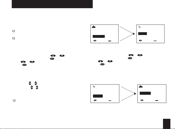
• In the Main Setup Menu, use or to highlight
“Weather Mode”, then press .
• Use or to scroll to highlight the “BARO” screen
• Press to enter the “REF BARO” screen
• Set the reference altitude to zero for station pressure.
Set it to your current altitude if you want barometric
pressure
Baro—Displays current Barometric Pressure
Ref Alt—Use
Sync Alt—Use or to switch “On” and sync the Baro
reading to the “Altitude” screen
When “Sync Alt” is turned “On,” the current
“Density Altitude” screen data is calculated from the
absolute values of station pressure, relative humidit y
and temp., and is not aected by the reference values
entered in the “Baro” and “Altitude” screens.
to set the known Altitude
or
Barometric Pressure data is automatically used as a
reference for Altitude, and both screens will show
accurate readings.
REF ALT
Alt 877
Ref.Baro 30.97
SyncBaro On
adjust exit
Setting Altitude
• In the Main Setup Menu, use or to highlight
“Weather Mode”, then press .
• Use or to highlight the “Baro” screen
• Press to enter the “REF ALT” screen
• Set the reference altitude to your current altitude.
When “Sync Baro” is turned “On,” the current Altitude
data is automatically used as a reference for Barometric
Pressure, and both screens will show accurate readings.
REF BARO
Baro 30.15
Ref.Alt 115
SyncAlt On
adjust exit
syncs
syncs
REF BARO
Baro
Ref.Alt 877
SyncAlt
adjust exit
REF ALT
Alt
Ref.Baro 30.15
SyncBaro
adjust exit
9
Page 10

BASIC NAVIGATION & GET TING STARTED
THE KES TREL HAS SEV EN NAVIGATION KEYS:
Capture
Left-Arrow
Power On/
Escape Key
Quick Tips:
Your Shooter's Weather Meter with Applied Ballistics
(AB) can operate in Weather mode or AB mode. For
instructions related to Weather Mode, see page 23.
Compass must be calibrated in order for directional
features to work in AB mode. Compass calibration can be
done from the main menu screen. See page 7.
Pressing
When a ballistics parameter is underlined, this indicates
that the value cannot be changed manually on the
current screen. This is either because it is a calculated
value or determined by the sensors. Press and hold for
2 seconds to power down the Kestrel regardless of current
10
Up-Arrow
Down-Arrow
Backlight
Right-Arrow
Center Key
will allow you to exit out of a particular screen.
screen. Press twice in rapid succession to instantly
change between Weather mode and AB mode.
Any changes in information are automatically saved
upon exiting the current screen. There are four
exceptions to this rule where an “accept” screen appears
upon exiting: the Target Range estimator, the Target
Speed estimator, and the MV and DSF Calibration
screens.
Getting started with AB Mode
The three main data input groups are gun, target
and environment. The aiming solutions for Elevation,
Windage and Coriolis are displayed on the Main AB
screen.
1. Gun Information 2. Target
GUN Laru308
MV 2550FPS
DC G1
BC 0.475
BW 175gr
BD 0.308in
BL 1.240in
ZR 100m
BH 2.75in
ZH
ZO
RT 11.25in
RTd Right
EUNIT mil
Eclck n/a
Wunit mil
Wclck n/a
Cal MV
Cal DSF
View DSF
Clear DSF
TARGET
Active
TR
DoF
g
Ide
Icos
TS
TD
WD
WS1
WS2
A box indicates amount of
data shown on display.
Data below box indicates
additional information
available by pressing .
*Note: Please see p. 28 for
abbreviation glossary.
1.000º
0mph
5mph
10mph
Yes
1000
000º
0˚
L-R
12oc
Page 11
GUN SELECTION
3. Environment
ENVIRONMENT
Lat
Temp
SP
RH
Dalt
store up to 16 guns. A user-created gun is dened as a
gun that has been modied for one or more parameter
values of the New Gun or any of the precongured guns.
A precongured gun is any gun loaded onto the Kestrel
using the AB Gun Loader software.
When a New Gun is modied, the name instantly
changes to UserGunX (where X is a number sux to
ensure the name is unique). If a precongured gun
(whose name ends in a letter) is modied, a number
will appear at the end to create a unique name. If a
precongured gun (whose name ends in a number)
is modied, a letter will appear at the end to create a
unique name.
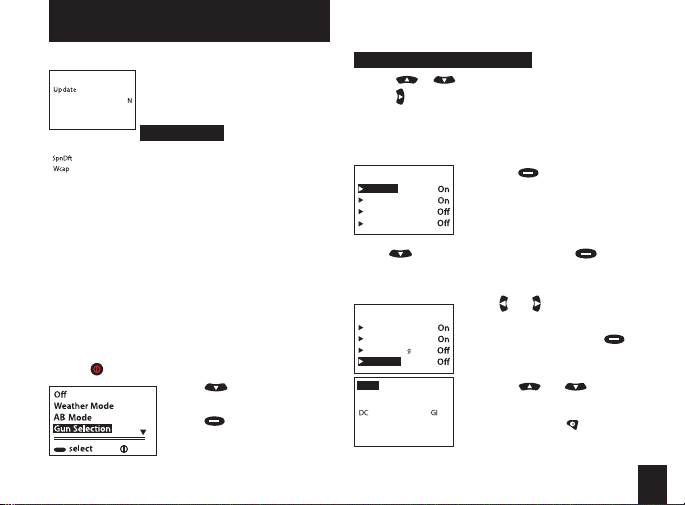
• Turn on the unit. From the Main AB screen,
press to access the Main Setup Menu.
These three main data groups
No
determine an accurate ring
42˚
solution. The rst step in getting a
75˚F
ring solution is selecting your gun.
29.48inHg
50%
Gun Selection
1729ft
The Gun Selection screen allows you
Yes
to choose a precongured gun or
Onetgt
build your own. You may create and
• Press to highlight “Gun
Selection.”
• Press to enter Gun
Selection Screen. Here, you
may choose a precongured
exit
gun or build your own.
To Choose a Precongured Gun:
• Press or to scroll through the dierent guns.
• Press to turn your selected gun “on” or “o.” “On”
means the gun is available to be selected in AB mode.
“O” means the gun is not available to be selected.
For example, setting multiple guns to “On”
allows you to quickly switch gun congurations
without going back to the Main Setup Menu.
Laru308
User Gun2
User Gun
300WinMag2
• Use to highlight New Gun and press .
• This will take you to the gun information screen
where you may adjust all gun parameters. Press up or
down to highlight the gun parameters.
MaruGun308
AR15a
300WinMag1
New Gun
GUN New Gun
MV
BC
BW
11 Gun select
• Pressing on a gun gives you
the option to edit or delete this
gun.
To Build A G un:
You can build and name your gun
on the gun selection screen.
• Use and to adjust each
11 Gun select
value.
• To name your gun, scroll up to
highlight “Gun” and press .
• You will see a cursor appear
under the rst letter of New
Gun.
• Use the and buttons
to scroll through the alphabet
ps
2900f
and numbers 0-9 and several
symbols. Pressing inserts a
0.533
space between characters. You
g
190
r
can choose between upper and
lowercase letters.
11
Page 12
GUN LIBRARY & INFORMATION SCREEN
• Once you’re on the desired letter, use to move
the cursor to the next space in the gun name.
Continue until the gun name is complete.
• When gun name is complete, press button to
save. (Gun will also automatically save upon
exiting screen.)
• Press to exit from the current screen.
Gun Library
There is room in the Kestrel for up to 16 guns. While it
is possible to copy a precongured gun to your Kestrel
and modify the parameter, you should use New Gun
and input all the parameters to ensure MV and DSF Cal
are accurately inputted. You can build a gun library on
a computer using the AB Gun Loader software, and
download the new gun library to the Kestrel (either via
Bluetooth® connection or the Kestrel wired interface).
Downloading a new gun library will automatically
overwrite the previous guns in the Kestrel.
*Note: You should upload any user-created guns to the AB
Gun Loader software that you want to save before downloading new guns. The new guns will overwrite current
stored Kestrel guns.
Gun Information Screen
Once you have selected your gun, you’re now ready to
enter or modify all relevant parameters pertaining to the
set-up of your rie. These parameters include muzzle
velocity, drag curve, ballistic coecient, bullet weight,
bullet diameter, bullet length, zero range, zero height,
zero oset, bore height, rie twist, rie twist direction
and sight adjustment (click).
• On the Gun Information screen, use buttons to
12
highlight the gun parameters.
• Use and to adjust the value.
• Press to enter the highlighted parameter’s
screen. Here you are also able to adjust the
parameter’s value as well as the unit of measure.
(For example, meters per second to feet per second.)
• Press to exit to Main AB screen once all values are
correct.
See below for more information on Muzzle Velocity, Drag
Curves and Calibration.
Muzzle Velocity
• Use and to highlight “MV.”
• Press to enter MV screen.
• Use and to adjust the value.
Notes on Muzzle Velocity
• When a bullet is in the transonic range, a small dot
will appear to the left of the muzzle velocity value
(gure 1).
• When a bullet is in the subsonic range, a larger dot
will appear to the left of the muzzle velocity value
(gure 2).
GUN Laru308
MV
BC
BW
• In cases where the bullet is supersonic, there are no dots
Figure 1 Figure 2
next to the muzzle velocity value.
•
1360fps
0.470
175
GUN Laru308
MV
BC
g
r
BW
1103fps
•
0.470
175
g
r
Page 13

GUN LIBRARY & INFORMATION SCREEN
MV-Temp Table
This allows you to enter and maintain a table of muzzle
velocities based on temperature. If an entry is input
into the table, the muzzle velocity is applied at all
temperatures (this means that the value is then locked
and cannot be altered by using and on the gun
information screen). If two or more entries are input into
the table, the Kestrel uses the linear interpolation and
the temperature sensor to determine the appropriate
muzzle velocity. (Note: this value will only change if
the temperature changes and you exit and re-enter
the gun information screen; once a muzzle velocity
value is entered for a particular temperature, you can
not make another muzzle velocity value for the same
temperature.)
• To access MV-Temp table, scroll to MV (Muzzle
Velocity) to highlight it and press , then use
to scroll to MV-Temp and press to enter.
Muzzle velocity
MV
per sec
feet
p
MV-Tem
Table item
Temp
MV
Clear
• Press while “New entr y” is
highlighted to enter the Table
fps
2900
Item screen.
• Use or to scroll to
“Temp” and “MV.” Use and
to adjust each value.
• To clear a Table Item, scroll
down to Clear and
press .
• Press to exit to return to the
10ºF
Gun Information
fps
2900
screen.
GUN INFORMATION SCREEN CONT.
Drag Curves
The Kestrel with Applied Ballistics allows you to use G1 or
G7 drag curve model, or AB's custom drag curves.
• To select the appropriate drag curve, scroll to "DC."
• Use and to scroll through options.
• If a custom drag curve is used, no further adjustment is
necessary. If using G1 or G7 drag curves, you must adjust
the BC by scrolling down and editing to the proper value.
For more information on the custom drag curves, please see
page 18.
Calibrate Muzzle Velocity
This allows you to calibrate your muzzle velocity based
on the actual drop of a round at a range where the bullet
is supersonic. With the range and the drop entered, the
Kestrel automatically adjusts muzzle velocity to match.
• To access the muzzle velocity Cal, scroll to Cal MV to
highlight it and press .
MV Cal 1398m
Range 1275m
Drp 9.35mil
-Cal
MV 2826fps
• Use and to adjust the range at which you are
ring. The Drop will update with the range.
• Use to scroll to “Drp.” Use and to adjust the value
to match the observed drop of the bullet at range.
• Use to scroll to “Cal" and press . The Calculated
Calibrated Muzzle Velocity value will be displayed at the
bottom of the screen.
• Press to exit to return to the Gun Information
The number shown to the top right
of the screen is the suggested range
distance at which to calibrate
muzzle velocity. This range is
calculated from when the bullet is
at a speed of Mach 1.2.
13
Page 14

GUN INFORMATION SCREEN CONT.
screen. The Kestrel will ask if you want to accept the MV
Calibration. Selecting "Yes" will use the Cal MV to update
the MV listed in the Gun Information screen.
For more information on Ballistics Calibration, please
see page 18.
Drop Scale Factor (DSF)
This allows you to enter and maintain a table of drop
scale factors (DSF) that utilize observed drop at range
to calibrate the elevation computation. The number
shown to the top right of the screen represents the
suggested range distance at which to apply a drop scale
factor for transonic ight. Additional drop scale factors
can be added to the DSF table by shooting at greater
distances including subsonic ight. Attempting to enter
an additional drop scale factor that is closer in range
distance than existing DSF table entries will invalidate
and erase the existing entries.
• To access the DSF Calibration, use and to scroll to "Cal
DSF" on the Gun Information screen.
• Highlight it and press
DSF Cal 1581m
Range 1275m
Drp 9.35mil
-Cal
DSF 0
14
.
The number shown to the top right of the
screen represents the suggested range
distance at which to apply a drop scale factor
for Transonic ight (Mach 1.0). Additional
drop scale factors can be added to the
DSF table by shooting at greater distances
including subsonic ight. Attempting to
enter an additional drop scale factor that is
closer in range distance than existing DSF
table entries will invalidate and erase the
existing entries.
and to adjust the range at which you are ring
• Use
• Use to scroll to “Drp.” Use and to adjust the
value to match the observed drop of the bullet at range.
• Use to scroll to “Cal” and press . The Calculated
Drop Scale Factor will be displayed at the bottom of the
screen.
Page 15

TARGET SCR EEN
• In order to accept the Calibrated DSF value, press
and select “Yes” by pressing .
Mach DSF
1 0.000 1.000
2 0.000 1.000
3 0.000 1.000
4 0.000 1.000
will update the rst row of your DSF table accordingly without clearing
the rest of your DSF table entries.
• Press to exit to return to the Gun
Information screen. The Kestrel will ask if you want to
accept the DSF Calibration.
• To view the DSF table, scroll to "View DSF" in the Gun
menu and press to see what DSFs have been
stored. You may repeat this step for up to six DSF
values. Please remember that entering DSF values at
ranges closer than previously entered will invalidate
DSF values at those longer ranges.
Target screen:
You can customize up to ve targets for location,
distance, direction, declination and wind.
• From the Main AB screen, use or to
TARGET
Active
TR
DoF
g
Ide
highlighted parameter’s screen.
The rst row of the DSF table will be
prepopulated with the mach value at which
muzzle velocity was calibrated and a drop
scale factor of 1.00. If ballistics calibration
was not completed, a default value of 1.0 will
be entered for you. However, calibrating your
muzzle velocity after establishing DSF table
highlight “Tgt” and press to
enter the Target screen.
• Use and to highlight a
Yes
parameter.
998m
• Use and to adjust values for
000º
each parameter.
0˚
• Press to enter the
Here you are able to adjust the parameter values as well
as the unit of measure. (For example, yards to meters.)
Multiple Targets
• You may create up to ve targets (A-E) by
highlighting “Target ” and pressing or to move
on to the next target. After changing targets, the
parameters can be changed by repeating the steps
outlined above.
Active
• The “Active” status of Target A defaults to “Yes”
because the Kestrel must have at least one active
target at all times.
• To make a target active, on the Target screen use
or to highlight “Active” and use or
to change to “Yes.” To make a target inactive, use
or to change to “No.”
• Setting a target’s “Active” status to “Yes” allows you
to view the ring solution for that target on the Main
AB screen.
• If multiple targets are active, you can use or to
scroll between all active targets (and their respective
ring solutions) on the Main AB screen.
Elevation
E
E
49.24
W
1.36/3.03
000°
Tgt
3oc
Wind
Target A is current
active target.
100 m
5m
R
p
h
Windage
HOLD
16.58
W
0.68/1.46
000°
Tgt
3oc
Wind
Target B is current
549 m
ph
5m
active target.
R
15
Page 16

TARGET SCR EEN CON'T
Target Range
• Use or to highlight “TR.”
• Use and to adjust the value.
Target Range Estimator
Range
TR
meters
Estimate
• Use to highlight “Estimate” and press to
enter Range Estimate screen.
• Use or to highlight a parameter.
• Use and to adjust values for each parameter.
• When all parameters are set, press to escape.
• An "Accept" screen will appear, scroll to "Yes" if you
would like to accept values. Use to select the
highlighted option.
Wind Direction & Wind Speed
There are two wind speed measurements on the target
screen (WS1 and WS2) for minimum and maximum
wind speed as well as wind direction (WD). You have
16
This function estimates the range
of a target based on size, image
998m
and calculated range.
• When “ TR” is highlighted, press
button to enter Range screen.
the option to manually adjust the
wind speed and wind direction
values or use the capture feature
to automatically get a reading.
Manual mode
• Use or to highlight “WD,” “ WS1”
or “WS2.”
• Use and to adjust values for each
parameter.
Capture mode
• In the Target screen, press to enter into either the
“WD,” “WS1” or “WS2” screen.
• Press to enter into capture mode.
• Face the back of the Kestrel meter directly into the
wind and press to start and stop the capture
mode. Please ensure Kestrel impeller cover is open.
• The data collected in capture mode will automatically
adjust the “WD,” “ WS1,” and “WS2” values in the Target
screen.
*Note: WS1 can never be greater than WS2 value. The
WS2 value will automatically adjust to ensure that this
remains true.
Direction of Fire
Direction of Fire (DoF) is an absolute frame of reference
to true north. The value is the direction the gun barrel
is pointing with respect to the values on a compass.
Direction of Fire can be manually adjusted or obtained
using the ”Capture” feature.
Manual mode
• Use
or to ensure that “DoF” is highlighted.
• Use and to adjust the value.
Capture mode
• When “DoF” is highlighted, press
DoF screen.
• Use to scroll to “Capture.”
• Press to enter into the capture mode.
• Face the back of the Kestrel directly toward the target
and press .
• The data collected in capture mode will automatically
adjust the DoF value in the Target screen.
*Note: Compass must be calibrated in order to capture DoF.
See p. 7 for calibration steps.
to enter the
Page 17

TARGET SCR EEN CON'T
Inclination Angle
Inclination angle is the angle between the target and
the horizontal as seen by the shooter. This variable is
expressed in the Target screen as “Ideg” or “Icos,” where
Ideg is in degrees, and Icos is the cosine angle. These
can be manually adjusted by highlighting one and using
the and to change the value. Changing one will
automatically change the other appropriately.
Target Speed
• Use or to highlight “TS.”
• Use and to adjust the value.
Speed of motion
TS
miles per hour
Estimate
• Use to highlight “Estimate” and press to
enter Speed Estimate screen.
• Use or to highlight a parameter.
• Use and to adjust values for each parameter.
• When all parameters are set, press to escape.
• An "Accept" screen will appear, scroll to "Yes" if you
would like to accept values. Use to select the
highlighted option.
Target Direction
• Use to highlight “TD.”
• Use and to adjust “L-R” (left to right) or “R-L”
(right to left).
Target Speed Estimator
This function estimates the speed
ph
0m
of a target based on range,
movement, and time.
• When “TS” is highlighted, press
button to enter Speed of
Motion screen.
ENVIRONMENT S CREEN
ENVIRO NMENT SCREE N:
The Environment screen contains all atmospheric
parameters, such as temperature, station pressure, and
relative humidity. Setting the “Update” parameter to
“Yes” automatically imports the Kestrel’s sensor data
into the Environment screen. The “Update” parameter
can also be set to “No” when it is highlighted by using
or ; while in this setting the temperature (Temp),
station pressure (SP), and relative humidity (RH) can be
manually adjusted.
ENVIRONMENT
Lat
Temp
SP
29.48inH
to “No.” When on the “Yes” setting, the Spin Drift is taken
into account for the ballistics solutions.
Coriolis aects all automatically calculated in the ballistic solutions. In order to turn o Coriolis eects, please
set the Latitude and Direction of Fire to zero.
*Note: station pressure (“SP”) is pressure reading that is unadjusted for sea level. Sometimes, this is mistakenly called
barometric pressure in ballistics software. Barometric
pressure is a pressure reading adjusted for sea level. When
shooting, station pressure is required. Station pressure can
be measured with the Kestrel by setting the reference altitude to zero on the Barometric Pressure screen in weather
mode; although, the ballistics solution will use station
pressure regardless of the altitude settings.
• Use or to highlight a
parameter.
• Use and to adjust the
No
values for each parameter.
42˚ N
75˚ F
g
Spin Drift will default to “Yes”
unless you manually change it
17
Page 18

RANGE CARD SC REEN
RANGE C ARD SCREEN
The Range Card screen shows detailed information
about the ballistic solution at various ranges that apply
to the currently selected target and gun. The screen
displays three columns comprised of the Range and
Elevation (in the left two columns) and one other
variable. The other variable that can be displayed is
ballistics solutions based on “Wnd1”; “Wnd2”; “Lead”;
or further information on bullet ight characteristics
such as remaining velocity (“RemV”); remaining energy
(“RemE”); time of ight (“ToF”); and maximum ordinate,
or height above the line of sight to the target (“MaxO”).
Please see Page 29 for a sample Range Card.
• Use or to scroll to a particular range.
• Use and to scroll across and view all
available parameters.
RANGE CARD
Elv
Rng
300
400
500
Example: "Rng" and "Elv" columns remaining xed while
third column can be changed.
Range Increment
• Use while in the Range Card to enter the
• Use and to adjust the range increment to the
Wnd1
5.50
L0.13
9.42
L0.19
14.06
L0.27
Range Settings screen.
desired value. You may adjust the increments to
show in 10, 20, 25, 50, or 100 units of measure (yards
or meters).
18
RANGE CARD
Rng
Elv
300
5.50
400
9.42
500
14.06
RemV
1991
1823
1666
• Press to exit "Range Increment" screen.
Note: The Range Card will display range values up to 4000
yards, or the closest equivalent in meters, depending on the
range increment.
Remaining Velocity
• A small dot will appear to the left of the remaining
velocity value to indicate the bullet is in the transonic
range.
• A larger dot will appear to the left of the remaining
velocity value to indicate the bullet is in the subsonic
range.
RANGE CARD
Rng
800
900
1000
RemV
.1272
.1177
.1101
RemE
629
538
471
Page 19

BALLISTICS SC REEN
BALLIS TICS SCREEN
The Ballistics screen displays complete information
about the ballistic solution that pertains to the currently
selected target and gun. The only parameter whose
value can be altered in this screen is the “Range” (this can
be done by using and to adjust the value).
• Use or to scroll to a particular parameter.
• Use to enter into a parameter screen for
further information about it or change unit of
measure.
• Use to return to the Ballistics screen.
Note: An R or an L will appear beside each solution to
indicate which side of the target you should aim.
APPLI ED BALLIstI cs' sIgnAturE fE AturEs
AUTOMATED BALLI STICS CALI BRATION &
CUSTOM DR AG CURVES
In an ideal world, shooters would go into the eld
knowing exactly how their chosen combination of
gun and ammunition will perform, calculated ballistic
solutions would always be correct, and a properly
delivered shot would always hit the target. In the real
world, ballistic data is often imperfect, and even well
delivered shots often miss. The best way to deal with
this is to allow ballistic parameters to be adjusted to
reect what is actually observed. When this is done
correctly, overall accuracy can be signicantly enhanced.
Ballistics calibration is used to calibrate the inputs of
the ballistic model to match the actual rie and round
used for shooting. In particular, the most signicant
CALIB RATI ON & CUSTOM DRAG CURVES
parameter is the muzzle velocity of the round (since the
Kestrel is measuring environmental conditions, and the
other specications of the rie are well known). By ring
at a target at a range where the round is supersonic
(Mach number greater than 1.2), the muzzle velocity
can be determined from the drop of the bullet at that
range. This works because the drag of the bullet is well
understood and accurately measured in the supersonic
region. Muzzle velocity calibration is the most important
calibration procedure, and should be performed if a
dierence in observed and calculated drop is noticed in
the supersonic region.
For longer range shots, in the transonic (Mach number
between 0.8 and 1.2) and subsonic (Mach number
less than 0.8) regions, additional calibration may be
necessary to compensate for variations in the ight of
the bullet. This is where drop scale factors are utilized
to rene the trajectory of the bullet to match observed
drops at longer ranges, but after verifying that the
muzzle velocity has been calibrated at supersonic
range. DSF calibration should be performed if a
dierence in observed and calculated drop is noticed
at ranges greater than the calibrated muzzle velocity
range.
Applied Ballistics’ model allows for the input of a
single BC when using a G1 or G7 curve. Once the
appropriate BC (provided by the bullet manufacturer)
has been entered, muzzle velocity calibration should be
performed, followed by DSF Calibration (if necessary) for
longer range shooting. It is recommended that custom
drag curves be used whenever possible for maximum
accuracy.
19
Page 20

The AB Kestrel includes two automated ballistic
calibration tools that dramatically increase accuracy at
long range. First, muzzle velocity is calibrated by ring
at a range where the round is supersonic. The user
enters the actual drop at that range, and the AB solver
computes the calibrated muzzle velocity automatically.
Second, for long range shooting - where the round
is transonic or subsonic - AB uses the actual drop at
another range to automatically compute the drop scale
factor (DSF).
This DSF provides a ner level of control in the transonic
and subsonic ights than BC-Mach/Dist tables,
especially when used with the custom drag curves that
Applied Ballistics has computed for many common
bullets. While AB's solver supports the use of G1 and G7
ballistic coecients, these custom drag curves oer a
new level of accuracy that cannot be matched by the
conventional G1/G7 ballistic tables.
Custom drag curves are accessible through the AB Gun
Loader software. See page 21 for download location.
20
BLUETOOTH SETUPCALIB RATI ON & CUSTOM DRAG CURVES
To transfer your Kestrel’s real-time and logged data
wirelessly and automatically to a laptop, PDA or
smartphone (Android only at this time), follow these
setup steps. If you do not have a Bluetooth unit you
will need the PC Interface cable.
Enable the Kestrel’s BLUETOOTH Capability
• Press to enter the Main Menu.
• Use or to highlight “Bluetooth,” then press
.
• Use or to change from “O/Disabled” to “On/
Ready.”
Set BLUETOOTH Range
In Bluetooth screen:
• Use
or to highlight “Range”.
• Use and adjust the range to “Low” (3ft), “Medium”
(10ft), or “High” (30ft). NK recommends using "High".
Obtain your Kestrel BLUETOOTH PIN and ID
For added security, each Kestrel comes with a unique
PIN and ID number to ensure proper pairing.
In the Bluetooth screen:
• Use
to highlight “Info,” then press to view your
unique ID and PIN.
Pair Your Kestrel with Your Computer
First, make sure your Kestrel unit’s Bluetooth and your
computer's Bluetooth are enabled. Open the Bluetooth
management software on your computer to add a
Bluetooth connection and follow the prompts to enter
the PIN. A COM Port will be assigned in the communicator
software. To understand which COM Port is being used,
please check your computer control panel settings.*
Page 21

BLUETOOTH SETUPCON'T
QUICK KEYS: DIRECTION O F FIRE & WIND SPE ED
This is a general guideline for pairing your Kestrel with
your computer. Individual Bluetooth software programs
and navigation may vary, and some computers do not
come equipped with Bluetooth capability and will need
additional products to communicate via Bluetooth.
* A “Bluetooth Error” screen will appear on the Kestrel if
pairing is unsuccessful.
Please see connecting my Kestrel using Bluetooth on
www.nkhome.com for further informati on.
Set Up Kestrel Communicator Software
• Go to: http://www.nkhome.com/support/pdfs.html.
Download and install the Kestrel Communicator
Software from this link.
• Once installed, the “Kestrel Communicator” icon will
appear on your desktop. Click on the icon and use
the “Help” tab to nd full instructions for use.
Set Up Applied Ballistics Gun Loader Software
• The Applied Ballistics unit comes pre-loaded with
six custom curves. In order to gain access to the full
library of available custom curves, you will need to
download this application and ensure that you have
the ability to load guns to your Kestrel unit from your
PC via Bluetooth connection or IR Docking Station.
• Go to http://www.nkhome.com/ABProleLoader.html
to download and install the Applied Ballistics Gun
Prole Loader PC application.
• Prole Loader instructions can be found at www.
nkhome.com/ABproleloader
QUICK K EYS: DIRECTIO N OF FIRE & WIND S PEED
The Direction of Fire (DoF) and Wind Speed (WS1 &
WS2) Quick Key feature allows you to quickly and easily
change the values of these parameters from the Main
AB screen without entering into the Target screen. It
minimizes the number of button presses and time by
instantly capturing these values from one screen- the
Main AB screen.
Direction of Fire Quick Key
• Pressing the button while Tgt is highlighted will
enter the DoF setting mode.
• The Tgt heading will change to to indicate the
setting mode.
• The direction will be continuously updated on the
target line.
• Pressing the button again will capture the
current direction as DoF.
• Nex t the wind heading will be highlighted, follow
the directions below wind speed quick key
Wind Speed Quick Key
• Pressing the button while Wind is highlighted
will enter the Wind setting mode.
• The Wind heading will change to to indicate
the wind setting mode.
• The moving 5-second average for windage and
wind speed will be continuously updated on the
wind line.
• The moving 5-second average for wind solution will
be continuously updated.
• Pressing the button again will capture the
current wind speed.
• The Wind heading will return to its normal state.
• The Wind line will show the captured relative wind
direction and wind speed.
• After capturing wind speed, DoF is not automatically
selected. Use Manual DoF rst if you need to
21
Page 22

WEATHER MODE
SETUP & OP TIONS
Main Se tup Menu
• When unit is on, press
which is used to customize preferences.
• Press
and to scroll through the options.
• Press to select the highlighted option.
Date and T ime Setup
• After battery installation, the meter will automatically
enter the Date and Time Setting mode.
• Press and to scroll to each option.
• Press and to adjust each option.
• Press the button to exit to the Main Setup Menu.
System
Contrast, auto shutdown, and calibrations can be
recongured as needed in the System screen.
• Use or to highlight one of the following
options:
Contrast
• Press or to increase or decrease the display contrast
from 0 (lightest) to 20 (darkest).
Auto Shutdown
• Press or to set the time at which the display will
automatically shut o after non-use (choose 15 min, 60
min, or O to de-activate auto shutdown).
Battery life will be shortened if the Auto Shutdown is
turned to “O.”
Baro Cal
Recalibration of this sensor is not recommended without
speaking to an NK technician. See “Barometric Pressure
22
to access the Main Setup Menu
& Altitude Setup” section on page 9 for calibration
instructions.
Humidity Cal
Recalibration of this sensor is not recommended without
speaking to an NK technician. Full humidity calibration
instructions are provided with the Kestrel RH Calibration
Kits. The unit may also be returned to NK for calibration. Visit
www.nkhome.com for more information.
Date & Time
to enter the Main Setup Menu.
• Press
• Use
or to highlight Date & Time.
• Press to enter the Date & Time Screen.
or to change each value.
• Press
Language
Display text can be set to 1 of 5 languages: English, French,
German, Italian, and Spanish.
• Press or to scroll the desired language.
• Press to select the highlighted language.
Restore
This menu contains options for global settings of all units
to metric or imperial, and returning the reference values for
the Alt and Baro screens to default (0 ft, 29.92 inHg).
To change units:
• Press or to scroll to the desired setting and
press or .
To return the reference values for the Baro and Alt screens
to default:
• Scroll to Defaults and press or .
Page 23

SETUP & OPTIONS CONT.
Memor y Options
• Press or to scroll to one of these options:
Clear Log Go Press or to clear stored data
Reset MMA Go Press or to clear Min/
Auto Store On Press or to turn “On”
Store Rate* 1hr Press or to increase or
Overwrite On Press or to turn “On” (will discard
Man Store On Press or to turn “On” or “O”
* When unit is o, data will continue to be stored unless the
2 sec or 5 sec Store Rates have been selected.
Data Storage
To manually store data, press the button. The screen
will conrm data storage status.
• Data Stored: veries that data was captured and will
appear on chart.
• Full: indicates overwrite is o and data log is full.
(will also cl ear Min/Max/Avg lo g).
Max/Avg data
(Chart data will remain intact).
(data will automatically store
at Store Rate) or “O ” (data
will only store when manually
captured with the button).
decrease frequency at which
data is stored (from 2 sec - 12
hr).
oldest data point to capture new
data when log is full) or “O” (will not
capture new data when log is full).
(O will dis able button).
• O: indicates that the Manual Store button has been
disabled.
See Main Setup Menu for more information on memory.
Measur ements
Use this setup to “hide” unwanted M easurement screens
from the normal Measurement navigation.
23
Page 24

SETUP & OPTIONS CONT.
• Use or to scroll to the desired Measurement
screen.
• Press or to turn screen “On” and “O”.
The Kestrel Meter will continue to log data for hidden
measurements. To view logged data of the hidden
measurement, go to Measurement setup, select the
Measurement screen you want to view, and turn it back
“On.”
When the Kestrel is in Chart mode, the upper and lower
limits of the graph scale may need to be adjusted to fully
view all data points. You can customize these value limits
using the Graph Scale setup.
• Press or to scroll to the Measurement you want
to adjust, then press .
• In the new screen, use or to highlight “Set High”
or “Set Low”.
• Pres s or to adj ust the value limit o f your
chosen op tion.
Units
This setup option lets you sele ct units of measure to best
suit your application.
• Use or to scroll to each measurement.
• Press or to change the unit of measurement.
User Scr eens
The Kestrel allows you to set up to 3 customized User
Screens that will display 3 current Measurement values
on the same screen. These screens are helpful for quick
reference if you need to monitor multiple measurements
at once. The User Screen option allows you to c ustomize
your user s creens.
24
• Press or to highlight .
User Screen 1, 2 or 3, then press .
• Use or to set your preferred measurement op tion.
• Press or to highlight
the remaining lines, and us e or to set those
Measure ment options.
Repeat these steps to set up the other User Screens.
When accessed through the Measurement navigation,
each User Screen will display current data for the chosen
measurements as programmed.
User Screen2
22.5 °F
48.6 %
1014.6 inHg
Sample User Screen
Page 25

SCREEN NAVIGATION
Measur ement Scree ns
• Press or to scroll through the Measurement
screens.
Measur ement Modes
• From your chosen Measurement screen, use or to
scroll through the Mode options:
Current: Displays instantaneous reading.
Min/Max/Avg: Displays the Minimum, Maximum, and
Average readings from stored data (Displays --.- if no data
has been stored).
Chart: Displays graph of stored data points for each
measurement.
Current Min/Max/Avg Chart
TEMP F
76.4
To View Chart Data:
• Press while viewing a chart. A cursor will appear on
the most recent data point.
• Press or
TEMP F
Min 32.4
Avg 67.9
Max 84.0
to scroll through saved data:
56.0 F
Feb 27 16:58:14
TEMP F
— for data
The data value will be displayed at the top of the screen.
The date and time when each data point was stored will be
displayed at the bottom of the screen.
• Press or to review the chart data for other
measurements.
MAX/AVG FUN CTIONS - Wind Sp eed & Wind Chil l
These values are measured indepe ndently from stored
and charted data to allow the user to start and stop the
averaging period in the manner most appropr iate for
their application. Averaging on all wind- related values
will be started and stoppe d together.
To measure the se values:
• Pres s or to scroll to a wind m easurement
screen, t hen use or
to begin coll ecting data.
• Pres s
• Pres s again to stop data col lection and disp lay the
Maximu m and Average values .
This routine will work simultaneously for both
measurements, regardless of which one is displayed when
run. No other Min/Max/Avg or stored data will be aected.
to selec t Min/Max/Avg scre en.
• To clear data, press when the screen says “— clear”.
Other measurements will display min / max / avg data
based on the data stored in the log (using either autostored or manually captured data). This data can be
cleared by using “Reset MMA” under memory options.
Backl ight
• Press
to activate backlight for one minute.
• Press again to deactivate the light manually.
25
Page 26

IMPELLER REPL ACEMENT
Replacing the Kestrel Impeller
Press only the sides of the impeller when removing and
inserting to avoid damaging the precision hub bearing. [
] .
Figure 1
• Press FIRMLY on the impeller module to remove it.
• Insert the new impeller so the side that has the small
triangle (close to the perimeter) faces the front of the
Kestrel when installed.
26
Figure 1
• Orie nt one “arm” of the modu le straight up .
[ Figure 2]. Th e impeller can be p ushed in from eith er
side.
Figure 2
Kestrel
Page 27

USING THE BOOTLOADER
When new software updates become available, users can
update their Kestrel using the NK Bootloader software. To
do so, please follow these instructions;
Note: You will need to have either a Blueto oth capable Kestrel
or the PC Interface cradle and cable in order to upgrade your
Kestrel software.
1. Set up your PC to talk to the Kestrel using either
Bluetooth or the PC Interface Cradle.
2. Download the NK Bootloader soft ware from Applied
Ballistics page on the NK website: http://www.nkhome.
com/ABProleLoader.html
3. Extract the zip le to the desktop of the PC.
4. Click on Setup.exe and follow the instructions to install
the NK Bootloader software.
5. Once you’ve installed the le, click on the start button.
Locate and start the NK Bootloader software.
6. Click on File in the top lef t. Find the folder location of
where the BIN le was extracted from step 3 and select
that le.
7. Make sure your Bluetooth is enabled and Kestrel is
turned on and in range of the PC. If you are using the PC
Interface cradle, please have the Kestrel turned on in the
cradle and connected to the PC.
8. Select the correct COM port number and click start
download. It will take about 10 to 15 minutes to update
the Kestrel Software. You should see “REFLASH” on the
Kestrel unit while updating the code.
9. Once the progress bar is complete, the Kestrel software
has been updated and is ready for use.
27
Page 28

GLOSSARY OF TERMS BALLISTIC & ENV IRONMENTAL QUIC K REFERENCE
manually adjust both values.
Active gun: When a gun is made active, ballistic
solutions for that gun pertaining to all active targets are
readily displayed. Ballistic solutions for guns that are
inactive are not displayed.
Aiming/Ballistic solution: This consists of sight
corrections for windage, elevation, and in the case of
a moving target, lead for a selected active gun and
target, along with other calculated values such as bullet
velocity and energy. On the main AB screen, only
elevation and windage are displayed. On the Range
Card and
Ballistic Info screens, detailed ballistic solution data is
available.
Subsonic: The speed at which the bullet is slower than
the speed of sound. Bullet velocities in this range will be
displayed with a large dot to the left of the value.
Supersonic: The speed at which a bullet is gonig faster
than the speed of sound. Bullet velocities in this range
will have no dot next to them.
Target:
A target is characterized by its direction, range,
inclination angle, and applicable wind; a moving
target has a direction and speed of motion. Targets are
identied by a single letter: up to ve can be created,
designated by the letters A through E. It’s important to
note that wind is specic to a target – each active target
has its own wind specication.
Transonic: The speed at which the bullet slows to
the speed of sound. This is also seen as the boundary
between supersonic and subsonic. Bullet velocities in
28
this range will be displayed with a small dot to the left
of the value.
Target Screen
Active – tells whether this target is currently active
TR – target range
DoF – direction of re (relative to true north)
Ideg – inclination angle (negative means the target is
below the shooter)
Icos – inclination cosine (cosine of the inclination angle)
TS – target speed
TD – target direction of movement
WD – current wind direction (direction from which wind
is blowing, relative to DoF)
WS1 – minimum current wind speed
WS2 – maximum current wind speed
Gun Screen
MV – muzzle velocity
DC – drag curve. The amount of drag (air resistance)
applied to the bullet across various bullet speeds.
BC – bullet ballistic coecient
BW – bullet weight
BD – bullet diameter
BL – bullet length
ZR – zero range
BH – bore height
ZH – zero height. If your Point of Aim does not exactly
equal your Point of Impact at the zero range, you can
enter how much the group is o center. In other words,
if you have 1/4 MOA clicks on a scope and the zero is
0.1" high, you can enter this here to account for the error
that's less than 1 click. A negative value indicates down.
ZO – zero oset. Same as above for the horizontal
direction; use a negative value to indicate left.
RT – riing twist rate (distance in which bullet achieves
360 degrees of rotation)
Page 29

BALLISTIC & ENV IRONMENTAL QUIC K REFERENCE
RTd – riing twist direction (right = clockwise from
the shooter’s perspective)
Click – assigns an angular value to sight clicks
DSF - drop scale factor
Eunit elevation unit – The units used for elevation
adjustments (Eclick). Can be mils, clicks, tmoa (True
Minute of Angle), smoa (Shooter’s Minute of Angle).
Eclick – elevation adjustment necessary for the ring
solution in the units specied above.
Wunit – windage unit – The units used for windage
adjustments (Wclick). Can be mils, clicks, tmoa (True
Minute of Angle), smoa (Shooter’s Minute of Angle).
Wclick – windage adjustment necessary for the ring
solution in the units specied above.
Environment Screen
Update – controls whether values for temperature,
barometric pressure, and relative humidity are
obtained automatically (yes) (from the Kestrel’s weathermeter functions) or are manually set by the user (no)
Lat – allows the user to specify the latitude that will be
used when calculating Coriolis corrections
Temp – temperature
SP – station pressure (actual pressure at the
gun’s location)
RH – relative humidity
Dalt – density altitude (calculated from pressure,
temperature & humidity)
Spin Drift – controls whether Spin Drift corrections are
included in ballistics calculations
Wcap – toggles between applying windage correction
to just the current active target (one tgt) or to all targets
Range Card Screen
Elv – the elevation sight correction
Wnd1 – the windage sight correction based on WS1
Wnd2 – the windage sight correction based on WS2
Lead – the lead sight correction (for a moving
target)
RemV – the downrange bullet velocity
RemE – the downrange bullet energy
ToF – the bullet’s time of ight
SpnD – the amount of Spin Drift being applied to the
bullet
Ballistics Data Screen
Range – the range for which the ballistic solution
is calculated
Elv – elevation correction
Wnd1 – windage correction (based on WS1)
Wnd2 – windage correction (based on WS2)
Lead – lead correction, based on specied
target motion
vCor – vertical Coriolis correction
hCor – horizontal Coriolis correction
Drft – bullet drift correction
RemV – remaining velocity
RemE – remaining energy
ToF – time of ight
MaxO – maximum ordinate (highest point the bullet
reaches in ight)
Drp – total drop distance
Rtrns – range at which transonic velocity
transition begins
29
Page 30

BALLISTIC & ENV IRONMENTAL QUIC K REFERENCE CON'T
Rt 75% – distance at which a bullet is 75% through
the transonic range
Rsubs – range at which bullet velocity
becomes subsonic
Range Estimation Screen
Target – the size of the target on which estimation
is based
Image – the apparent size of the target as it appears
in a telescopic sight
Range – the calculated range, based on the target
and image sizes
Speed Estimation Screen
Range – the range at which the speed estimation
will be done
Mvmt – the apparent movement of the target as it
appears in a telescopic sight
Time – the time (in seconds) during which
movement was measured
Speed – the calculated speed, based on range,
movement and time
Cal MV Screen
Range – the range at which test ring is being done
Drp – the elevation correction calculated for the
specied range, updated by user with observed
drop
MV – the muzzle velocity used in the current elevation
calculation
Cal DSF Screen
Range – the range at which test ring is being done
30
Drp – the elevation correction calculated for the
specied range, updated by user with observed drop
DSF – the drop scale factor used in the current elevation
calculation
Page 31

FULL R ANGE CARD DATA SAMPLE
Sample of full Range Card data relative to data seen on display.
Rng Elv Wnd1 Wnd2 Lead RemV RemE ToF SpnD
50 2.42 0.06R 0.10R 1.06R 2727 2891 0.059 0.02R
100 0.62 0.09R 0.17R 1.07R 2633 2695 0.120 0.02R
150 .079 0.12R 0.26R 1.09R 2541 2509 0.183 0.02R
200 3.52 0.16R 0.34R 1.11R 2450 2332 0.249 0.02R
250 6.93 0.20R 0.44R 1.13R 2361 2164 0.317 0.02R
300 10.79 0.24R 0.53R 1.16R 2272 2006 0.388 0.02R
350 14.98 0.28R 0.63R 1.18R 2188 1861 0.461 0.02R
400 19.55 0.33R 0.73R 1.20R 2101 1716 0.538 0.02R
450 24.37 0.37R 0.83R 1.23R 2021 1588 0.617 0.02R
500 29.59 0.42R 0.95R 1.25R 1937 1459 0.700 0.02R
550 35.10 0.47R 1.06R 1.28R 1859 1343 0.786 0.02R
600 40.98 0.52R 1.18R 1.31R 1781 1233 0.876 0.02R
31
Page 32

FULL R ANGE CARD DATA SAMPLE CON'T
Rng Elv Wnd1 Wnd2 Lead RemV RemE ToF SpnD
650 47.24 0.57R 1.31R 1.33R 1705 1130 0.970 0.35R
700 53.92 0.63R 1.44R 1.36R 1631 1034 1.068 0.35R
750 60.99 0.68R 1.57R 1.40R 1560 946 1.170 0.35R
800 68.55 0.74R 1.71R 1.43R 1491 863 1.278 0.35R
850 76.62 0.80R 1.86R 1.46R 1423 787 1.390 0.35R
900 84.40 0.87R 2.01R 1.50R 1358 716 1.508 0.35R
950 93.51 0.93R 2.17R 1.54R ·1295 652 1.631 0.35R
1000 103.3 1.00R 2.33R 1.57R ·1236 593 1.760 0.35R
1050 113.8 1.07R 2.50R 1.61R ·1178 539 1.896 0.35R
1100 125.2 1.14R 2.68R 1.66R •1127 494 2.038 0.56R
1150 137.3 1.21R 2.86R 1.70R •1089 461 2.187 0.56R
1200 150.0 1.28R 3.03R 1.74R •1062 438 2.337 0.70R
32
Page 33

SPECIFICATIONS
Target
Gun
Feature Abbreviation Units Minimum Maximum
Active Targets N/A A through E 1 5
Target Range TR yards 25 4000
Wind Direction WD o’clock 1 12
Wind Speed WS1 or WS2 mph 0 50
Direction of Fire DoF degrees 0 360
Inclination Angle Ideg degrees -60 60
Inclination Cosine Icos no units 1.000 0.500
Target Speed TS mph 0 50
Target Direction of Movement TD Left to Right OR Right to Left
Name Characters N/A 0 through 9; A-Z; a-z; -+/.:&*
Muzzle Velocity MV fps 300 4500
Ballistic Coecient BC no units 0.100 2.000
Bullet Weight BW grains 10 1500
Bullet Diameter BD inches 0.10 1.00
Bullet Length BL inches 0.10 3
meters 23 3658
degrees 0 360
m/s 0 22
km/h 0 80
fps 0 73
knots 0 43
o’clock 1 12
m/s 0 22
km/h 0 80
fps 0 73
knots 0 43
and space
m/s 91 1372
grams 0.6 97.2
mm 2.54 25.40
33
Page 34

SPECIFICATIONS
Feature Abbreviation Units Minimum Maximum
Gun
Environment Station Pressure SP inHg 12.00 32.00
34
Bullet Diameter BD inches 0.10 1.00
Bullet Length BL inches 0.10 3
Zero Range ZR yards 25 1000
Bore Height BH inches 0.10 5.00
Riing Twist RT inches/revolution 1.00 36.00
Muzzle Velocity MV fps 300 4500
Twist Direction RTd Left OR Right
Riing Click /mil 1 10
Relative Humidity RH % 1 100
Station Pressure SP inHg 12.00 32.00
Spin Drift SpnD Yes OR No
mm 2.54 25.40
mm 2.54 76.2
meters 23 914
cm 0.25 12.70
cm/revolution 2.54 91.44
/tmoa 1 10
/smoa 1 10
mb 406.4 1083.6
hPa 406.4 1083.6
psi 5.89 15.72
meters -3271 9987
mb 406.4 1083.6
hPa 406.4 1083.6
Page 35

CHOOSING & USIN G BAT TERIES FOR YOUR K ESTREL
Your Kestrel meter is powered by t wo AAA size batteries. Here is a guide to selecting the right chemistry/type of battery
for your meter:
BATTERY TYPE EXAMPLE BRAND
Lithium AAA
Recommended by
Kestrel for most
applications!
Low Self-Discharge
Rechargeable NiMH
Alkaline AAA Duracell® Ultrapower
NAMES
Energizer® Ultimate
Lithium
*Energizer owns a
patent on Lithium
chemistry batteries in
the USA.
Eneloop®
Duracell®
StayCharged®
Tenergy® Centaura®
Energizer® Recharge
PowerPlus®
Duracell® Procell®
Energizer® Max
Rayovac®
(many others)
SELECTION CONSIDERATIONS
• Improved cold-weather operational range.
• Best capacity when streaming data via Bluetooth®.
• Relatively high cost. (Note: because the Kestrel is a low power
circuit, there is little advantage to the higher priced “Ultimate”
batteries.)
• Somewhat less available – need to purchase spares in advance.
• Precharged rechargeable batteries which hold their charge for
up to one year.
• Lowest capacity option.
• Option to charge multiple sets for use in the eld oers cost
savings, particularly with Bluetooth® data streaming.
• LESS likely to leak and cause corrosion when left in the Kestrel.
• Lowest cost option.
Most readily available.
• Easy to obtain and use for intensive, short-term operations.
• Restricted cold weather performance – Kestrel circuitry will not
operate below 0°F/-18°C.
• Environmental impact of disposal.
• MOST likely to leak and cause corrosion when left in the Kestrel.
Follow below guidelines for storage and removal carefully!
35
Page 36

CHOOSING & USIN G BAT TERIES FOR YOUR K ESTREL CONT.
We strongly recommend you use lithium or LSD NiMH
batteries at all times to avoid battery corrosion damage.
All alkaline batteries are prone to leaking, particularly as
they near full discharge. The potassium hydroxide that
leaks from an alkaline battery causes oxidation damage
to the circuit and components which is often irreversible
and is NOT covered under the Kestrel warranty.
IF YOU CHOOSE TO USE ALKALINE BATTERIES due to
cost or availability, you MUST:
• Remove the batteries for long-term storage (more
than one month of non-use). If you have your Kestrel
set to log data while o, it will slowly drain the
batteries, increasing the likelihood of leaking.
• Set your system battery selection to “Alkaline” to
obtain accurate capacity readings:
» Press to enter the setup menu.
» to “System”, to enter, to “Battery.”
» to select the correct battery type.
» to exit system setup.
• Change your batteries when below 20% capacity to
avoid fully discharging your batteries.
• Whatever batteries you choose:
• Use national name-brand batteries wherever
possible. Do not mix brands or chemistries of
batteries.
• Do not mix batteries of dierent ages or usage –
replace both batteries at the same time with new
batteries that have not reached their expiration date.
36
• Inspect your batteries occasionally (at least every
three months) and remove immediately if you notice
ANY moisture or white crystalline material at either
end.
• Always store your Kestrel meter within the specied
temperature limits: -22.0 °F to 140.0 °F | -30.0 °C to
60.0 °C. Be particularly careful not to leave a Kestrel
meter with batteries installed inside a hot vehicle in
the summer.
What to Do if you Have a Leak
If you notice you have a leaking battery, be careful not
to touch it with your bare skin or allow it to come in
contact with your eyes as the leaking material is caustic
and/or toxic. Remove and dispose of both batteries. If
possible, loosen and vacuum out any white powder. DO
NOT BLOW INTO THE COMPARTMENT TO REMOVE THE
POWDER – it can cause eye or skin damage and will be
driven further inside the unit. You may attempt to use a
cotton swab moistened with white vinegar to clean the
contacts and gently swab out the battery compartment.
Do not exert any force against the contacts inside the
battery compartment or you may bend or break them.
Allow the battery compartment to dry completely and
try installing fresh batteries. If your unit powers up you
may continue to use it. If not, you may contract Kestrel
Support to inquire about our Customer Loyalty Trade-In
Program which provides a generous discount towards a
replacement Kestrel meter.
Page 37

5YEAR L IMITED PRODUCT WARRANT Y
WARRANTY CERTIFICATE
Your Kestrel Pocket Weather Meter is warrantied to be free of defects in materials and workmanship for a
period of FIVE YEARS from the date of its rst consumer purchase. NK will repair or replace any defective
meter or part when notied within the warranty period, and will return the meter via domestic ground
shipping or NK’s choice of method of international shipping at no charge. The following are excluded from
warranty coverage: damage due to improper use or neglect (including corrosion); damage caused by
severe or excessive impact, damage caused by failed or leaking batteries, crushing or mechanical harm;
modications or attempted repairs by someone other than an authorized NK repair agent; impeller failure
not caused by a manufacturing defect; normal usage wear; failed batteries; and accuracy issues resolvable
by recalibration. If no warranty registration or proof of purchase is provided, the warranty period will be
measured from the meter’s date of manufacture.
Except for the warranties set forth herein, NK disclaims all other warranties, expressed, implied or
statutory, including, but not limited to, the implied warranties of merchantability or tness for a
particular purpose. Any implied warranties that may be imposed by applicable law are limited to
the term of this warranty. In no event shall NK be liable for any incidental, special or consequential
damages, including, but not limited to, loss of business, loss of prots, loss of data or use, whether
in an action in contract or tort or based on a warranty, arising out of or in connection with the use
or performance of an NK product, even if NK has been advised of the possibility of such damages.
You agree that repair, and (upon availability) replacement, as applicable, is your
sole and exclusive remedy with respect to any breach of the NK Limited Warranty
set forth herein.
All product liability and warranty options are governed exclusively by the laws of the
Commonwealth of Pennsylvania.
37
Page 38

38
Page 39

39
Page 40

By
NIELSEN-KELLERMAN
21 Creek Circle, Boothwyn, PA 19061
Phone: (610) 447-1555
Fax: (610) 447-1577
Web: NKhome.com
Email: info@NKhome.com
Please register your Kestrel Meter at NKhome.com
Kestrel® Weather and Environmental Meters
are designed and manufactured in the USA
NK#319915_REV1_13.10.23
 Loading...