

Kessler-Ellis Products MRT, MC2, MR2, MINItrol Series Installation & Operating Instructions Manual

MINItrol SERIES
INSTALLATION & OPERATING INSTRUCTIONS
MODELS
MRT
MC2
MR2
KESSLER-ELLIS PRODUCTS
99306 08/17/15
10 Industrial Way East
Eatontown, NJ 07724
800-631-2165 • 732-935-1320
Fax: 732-935-9344

Proprietary Notice
The information contained in this publication is derived in part from proprietary and patent data of the Kessler - Ellis Products
Company. This information has been prepared for the expressed purpose of assisting operating and maintenance personnel
in the efcient use of the instrument described herein. Publication of this information does not convey any rights to use
or reproduce it or to use for any purpose other than in connection with the installation, operation and maintenance of the
equipment described herein.
Copyright 1989, Kessler-Ellis Products Co.
Printed in USA. All Rights Reserved.
WARNING
This instrument contains electronic components that are susceptible to damage by static electricity. Proper handling* procedures must be observed during the removal, installation or handling of internal circuit boards or devices.
*Handling Procedure
1. Power to unit must be removed.
2. Personnel must be grounded, via wrist strap or other safe, suitable means, before any printed circuit board or other internal
device is installed, removed or adjusted.
3. Printed circuit boards must be transported in a conductive bag or other conductive container. Boards must not be removed
from the protective enclosure until the immediate time of installation. Removed boards must be placed immediately in a
protective container for transport, storage or return to factory.
Comments:
This instrument is not unique in its content of EDS (electrostatic discharge) sensitive components. Most modern electronic
designs contain components that utilize metal oxide technology (NMOS, CMOS, etc.). Experience has proven that even
small amounts of static electricity can damage or destroy these devices. Damaged components, even though they appear
to function properly, exhibit early failure.
ATTENTION
Cet instrument contient des composants électroniques qui sont susceptibles d'être endommagés par l'électricité statique.
Procédures de manipulation appropriées doivent être respectées lors de l'enlèvement, de l'installation ou de la manipulation
des cartes de circuits internes ou les périphériques.
Procédure de traitement
1. Mettez à l'unité doit être retiré.
2. Le personnel doit être mis à la terre, par l'intermédiaire de bracelet ou d'autres moyens appropriés, sûrs, avant toute carte
de circuit imprimé ou un autre dispositif interne est installé, enlevés ou ajustés.
3. Les circuits imprimés doivent être transportés dans un sac ou un autre récipient conducteur conductrice. Les conseils ne
doivent être retirés de l'enceinte de protection jusqu'à ce que le temps d'installation immédiate. Planches enlevées doivent
être placées immédiatement dans un conteneur de protection pour le transport, le stockage ou le retour à l'usine.
Commentaires:
Cet instrument est pas unique dans son contenu d'EDS (décharge électrostatique) des composants sensibles. La plupart
des conceptions modernes contiennent des composants électroniques qui utilisent la technologie de métal d'oxyde (NMOS,
CMOS, etc.). L'expérience a prouvé que même de petites quantités d'électricité statique peuvent endommager ou détruire ces
dispositifs. Les pièces endommagées, même si elles semblent fonctionner correctement, présentent une défaillance précoce.

TABLE OF CONTENTS
SPECIFICATIONS ................................................................................................... 1
DECODING PART NUMBER .................................................................................. 2
HOW TO MOUNT THE UNIT .................................................................................. 3
WIRING MINITROL ................................................................................................. 4
UP/DOWN CONTROL AND QUADRATURE INPUTS ............................................4
WHAT CAN YOU VIEW ........................................................................................... 6
OUTPUT JUMPER SELECTIONS .......................................................................... 6
MILLIVOLT INPUT OPTION JUMPER SELECTIONS ............................................ 6
OPERATING FRONT PANEL .................................................................................. 7
PROGRAMMING FLOW CHART ............................................................................ 7
PROGRAM CODES & DESCRIPTIONS ................................................................. 8
MINITROL TERMINATIONS .................................................................................... 9
CALCULATING SCALE FACTORS ......................................................................... 10
MINITROL PROGRAMMING PROCEDURE ..........................................................11
SETTING SCALING FACTORS .............................................................................. 11
SETTING THE COUNTER ...................................................................................... 12
SETTING THE RATE .............................................................................................. 13
SETTING THE LOCK CODE & LOCKING THE UNIT.............................................14
SETTING THE RELAYS & PRESETS ..................................................................... 15
OUTPUT WIRING ................................................................................................... 16
ANALOG OUTPUT OPTION ................................................................................... 17
RS232/RS422 SERIAL COMMUNICATIONS.......................................................... 18
TROUBLESHOOTING GUIDE ................................................................................ 21
WARRANTY


DESCRIPTION & SPECIFICATIONS
DESCRIPTION:
The MINITROL is a 6 digit totalizer / ratemeter with two level,
5 digit preset alarm control of total or rate. Inputs A & B have
separate scaling K-factors. The totalizer can be programmed
for “A” subtract “B”, “A” add “B” or A & B as separate totalizers,
with display and control of the “net” total and rate of "A". The
MINITROL is also available in 4 other versions. MC2: a two
preset totalizer with scaling, MR2: a high/low alarm ratemeter
with scaling; The “MC”: a totalizing counter only, and the “MR”:
a rate meter display only. If only one input is required, the unit
will display the total and rate from that one channel. The MINITROL can accept up to 10,000 pulses per second. It has a 5
digit oating decimal scale factor allowing total readout in true
engineering units and rate per second, minute or hour.
Input “A” simultaneously drives a ratemeter which can be programmed to display the basic frequency (rate per second) or
factored to show rate per minute or rate per hour. Simply push
the “VIEW” button to see either total or rate without losing a
count. Two separate 5 A relay contacts can be set to operate
at either rate or total presets in a latch or auto-recycle mode
with output timing from 0.1 to 99.9 seconds.
Two control outputs can be assigned to either the totalizer or
ratemeter and can automatically recycle at the batch or stay
latched until reset.
Up to 99 units can communicate to a host computer on a single
RS232 or RS422 loop.
When two inputs are received (A & B), the unit can either add
or subtract the two inputs or display the two inputs as separate
totalizers.
SPECIFICATIONS:
DISPLAY
6 digit, 0.55" High LED
INPUT POWER:
110 VAC ± 15% or 12 to 15 VDC
220 VAC ± 15% or 12 to 15 VDC
24 VAC ± 15% or 12 to 15 VDC
CURRENT:
250 mA DC max. or 6.5 VA AC
OUTPUT POWER (AC powered units only)
+12 VDC @ 50 mA, unregulated -10 + 50%
TEMPERATURE:
Operating:
+32°F (0°C) to +130 F (+54°C)
Storage:
-40 F (-40°C) to +200°F (93°C)
MEMORY
EEPROM stores data for 10 years if power is lost.
INPUTS:
3: High Impedance DC pulse input 4-30 VDC (high), Open or
0-1 VDC (low),10 KΩ imp. 10 kHz max. speed. Accepts simultaneous inputs. May be used with KEP 711 series or 715-1
encoders or PD & D series sensors.
3M: Mag. Input, Input A only, accepts 30mV input (50 V max. P/P)
signals 10 KΩ imp. 5 kHz max. (Input B, 4-30V)
3MB: Mag. Input, Inputs A & B, accepts 30mV input (50 V max. P/P)
signals 10 KΩ imp. 5 kHz max.
5: 4-30 V Count pulses on Input A, 4-30 V Direction Control input
(level) on Input B. May be used with KEP 715-2 Encoder.
5M: 30 mV Count pulses on Input A (50 V max. P/P) 4-30 V Direc-
tion Control input (level) on Input B
9: Quadrature, accepts 4-30 V pulses with 90° phase shift for
direction detection. May be used with KEP 716 encoder.
9MB: Quadrature, accepts 30 mV (50 V max. P/P) pulses with 90°
phase shift for direction detection.
NOTE: The Mag. inputs have ltering as follows: up to 300hz
@30mV, 5KHz @ .25V to 50V max.
RESET:
Front Panel: Resets displayed value and control output
Remote: 4-30 VDC negative edge resets COUNTER "A"
and control output
K FACTOR/SCALING
In the standard unit a xed K-Factor is used to convert the input
pulses to engineering units. The 5 digit K-Factor dividers, with dec-
imal keyed into any position, allow easy direct entry of any K-Factor
from 0.0001 to 99999. Separate factors may be entered for the 2
separate input channels.
CONTROL OUTPUTS:
Relays:
2 each N.O. Relay; 5 Amps120/240 VAC or 28 VDC.
(N.C. relay contacts and NPN transistor output
available with solder jumpers. Transistor output is
internally pulled up to 10 VDC through relay coil, sinks
from 10 VDC to .5 V @ 100 mA)
Analog Output:
An optional 4-20mA (0-20mA) output is available for
the Minitrol series. The output can be programmed
to track rate or total. This feature is available by
adding sufx A to the part number. Connections are
via a 2 terminal pluggable screw connector.
Programming is accomplished by using the front panel
in conjunction with rear dip switches.
Accuracy: 50uA worst case.
Compliance Voltage: 3 to 30 VDC non inductive.
1

SPECIFICATIONS
(continued)
DECODING PART NUMBER
RS232/RS422SERIAL INTERFACE
If the serial interface option is supplied, up to 99 units can be linked
together. (The terminal addressing the unit must be capable of
driving all loads in the loop.) Unit status and new set points can be
communicated by serial communication. Mode changes, however,
must always be made on the front panel. Data is transmitted at
selected baud rates using standard seven bit ASCII characters and
parity with two additional bits of “Start” and “Stop” to make up the
standard ten bit character.
Data is received and transmitted over standard EIA RS232 or RS422
levels. Each 10 bit character is made up of a start bit, 7 bit ASCII
code, parity bit and stop bit. Unit number, baud rate and parity are
entered in the “Program Setting” set up mode and remain in memory
even if power is off.
Note that the input impedance of RS232 is 3K or 7K Ohm worst
case. The terminal addressing the unit must be capable of driving
all loads in the loop. RS422 input impedance is much higher and
there is usually no problem driving 25 units. Unit serial transmit line
remains in a high impedance “OFF” state until addressed.
PRESETS
Two control outputs are provided. To set relay values, press “menu”
button until “Relay” appears on the display, the A and B outputs can
be assigned to the ratemeter (high/low), one preset for rate and one
for total, or two presets (2 stage shut off) on the A and B counters. A
5 digit value can be entered for both presets and the decimal point
location is the same as the counter. The outputs can be set to energize from 0.1 to 99.9 seconds or latch (0.0). If a value other than 0.0
is entered, the counters will auto reset at the preset . In the A-B or
A+B versions, the relays will be assigned to either net total or A rate.
LOCKOUT
Unauthorized front panel changes can be prevented by entering a
user selected 5 digit code, in the “LOC” , . mode. The front panel
can be completely locked out or the presets can remain accessible.
MINItrol (MRT, MC2, MR2)
Example: MRT A 3 1 A
Series:
MRT= 6 digits, counter / ratemeter
with presets and scaling.
MC2= 6 digits, counter only with
presets and scaling.
MR2= 5 digits, rate only with
presets and scaling.
Operating Voltage:
A= 110 VAC ± 15% or 12 to 15 VDC
B= 220 VAC ± 15% or 12 to 15 VDC
C= 24 VAC ± 15% or 12 to 15 VDC
Count Inputs:
3 = Standard, 4-30 VDC simultaneous inputs.
3M = Mag. Input, Input A only, 30mV input
(Input B, 4-30V)
3MB = Mag. Input, Inputs A & B, 30mV input
5 = 4-30 V pulses on Input A,
4-30 V Direction Control input on Input B.
5M = 30 mV pulses on Input A,
4-30 V Direction Control input on Input B
9 = Quadrature, accepts 4-30 V pulses
9MB = Quadrature, accepts 30 mV pulses (A & B)
Options (Multiple Options Available)
1= RS232 Communications
2= RS422 Communications
A= Analog Output (4-20/0-20 mA)
RATEMETER
Accurate to 4 1/2 digits (±1 display digit). The rate meter can be
programmed to accept almost any number of pulses per unit of measurement, sample from 2 to 24 seconds maximum, and auto-range
up to 5 digits of signicant information. In the “RPS” mode, the ratemeter displays in units per second, and in the “scale” mode, units per
hour or per minute. The unit will display the rate of the A Input only.
COUNTER
The two 6-digit counters can count at 10Khz speed. Each can have
a 5-digit dividing scale factor. The counter advances on the positive
edge of each pulse. Count up or down modes available, as are
quadrature inputs from encoders for position or length measurement.
The unit can be programmed to view the net value of "A+B" or "A-B",
or A and B as separate counters.
2

HOW TO MOUNT THE UNIT
FIG. A
3.622
(92)
1.772
(45)
4.437
(112.7)
2.625
(66.68)
0.587
(14.91)
4.245
(107.8)
BEZEL
GASKET
CUSTOMER PANEL
Panel Thickness 0.062" (1.5)
to 0.187" (4.7) max.
3.925
(99.7)
The unit is designed to be mounted with a gasket providing a water tight seal. Two mounting brackets are provided to secure
the unit to the panel. A panel less than .1" may distort if the clamps are screwed too tightly.
Slide the body of the unit through the rubber gasket. Insert the unit into the panel. As shown in "FIG. A", slide the brackets
up the groove to press against the back of the panel. Insert screws into rear of brackets and tighten them evenly and alter-
nately. Do not over tighten! A normal level of torque is required. Maximum torque should be 3" pounds.
This product is designed to be panel mounted and is NEMA 4 rated if proper mounting procedures are followed and the
required and supplied hardware is correctly used.
If the panel in which the unit is mounted is less than .125 of an inch thick, the possibility exists that there will be some exing.
Should this exing occur, the resulting deformation of the panel could cause a loss of the water tight seal. In case this should
occur, the use of silicone or other sealant would be recommended.
This product is designed to the NEMA 4 rated. However, the fact that we are unable to control either the location in which
the device is installed or the actual installation itself requires that the company's liability shall extend only to the repair or
replacement of a defective product.
We are prepared to offer additional assistance in those special situations where normal mounting methods do not seem to
satisfy the customers needs. This assistance may be obtained by calling the factory and asking for Application Engineering.
DIMENSIONS
3

WIRING MINITROL
The rear terminal contains 12 screw terminals for connecting #14 to #28 gauge wire.
The unit is controlled by a microprocessor and, therefore, an electrically "noisy" environment could cause operating problems.
The input power line should not be common to power lines for motors, pumps, contactors, etc.
The unit is designed to be immune from line or RF voltage interference. In some environments voltage spikes of over 100
volts, even 1000 volts, can occur. When common to a power line driving motors voltage uctuations can be extreme and
rapid. Lines driving DC or AC solenoids, relays, or actuators can also cause problems.
Four sources of noise can occur:
1) AC power line noise - If the unit cannot be connected to a clean power source, an inductive load suppressing device
(MOV as GE # V130LA1 or Resistor Capacitor as Paktron # .2 uf/220 ohm @ 400V) can be installed. Although locating
the suppressor across the AC supply at the unit should help, best results are obtained by connecting the suppressor
across the leads of the "load" at the device causing the spike.
2) Input line noise -The noise is carried on the input and D.C. ground lines. Make sure the input wires are never run into
the unit in a bundle with power input lines. Also, keep these input lines isolated from inductive lines from devices
drawing heavy loads. If there is a possibility of electrical noise, we recommend using shielded cable, with the shield
being hooked to the D.C. ground terminal on the instrument, and to "earth" at one point in the circuit, preferably at the
D.C. ground terminal of the unit.
3) Output lines - The unit has two relay outputs. When these outputs are used to run external relays or solenoids, spikes
can be generated upon activation. This noise can spread through the instrument causing operating problems. If the
source is a D.C. operated device, a general purpose diode (IN4004) placed across the solenoid prevents electrical
noise spikes. Connect the cathode (banded side) to the more positive side of the coil. If the source is an A.C. operated
device, use a MOV or Resistor Capacitor across the coil.
4) 12 VDC output supply - Noise can be generated on the 12 VDC output supply if it is used to drive inductive loads or if
the current draw exceeds 50 mA. Insure that all inductive loads have a diode (such as IN4004) across the coil and that
the current does not exceed 50 mA.
UP/DOWN CONTROL AND QUADRATURE INPUTS
QUADRATURE INPUT:
When programming the counter section for quadrature input, you must set the unit for A net B and A sub B (see step 2 in
programming section). This insures proper operation. The rate can only be viewed in one direction. If the unit is a ratemeter
only (MR2), connect only one of the quadrature channels to Input A (pin 5).
UP/DOWN CONTROL:
When using the up/down control option, Input A (pin 5) is the count input and Input B (pin 6) is the up/down control (direction)
input. The counter must be set for A net B and A sub B (see step 2 in programming section).
When the direction input is high (4-30VDC) the count inputs will count up, when the direction input is low (open or less than
1VDC) the count inputs will count down. The direction input must precede the count input by 1 msec when the unit is set
for low CPS and 1 usec when set for high CPS.
4
CONNECTING AC / DC POWER
D08N
1 COMMON
2 N.O. (N.C./NPN)
3 COMMON
4 N.O. (N.C./NPN)
5 A INPUT
6 B INPUT
7 12 V OUTPUT/ + DC INPUT
8 - DC (GROUND)
9 RESET INPUT
10 NOT USED
11 AC INPUT
12 AC INPUT
D12P
COUNT
POWER
GROUND
COUNT
GROUND
POWER
A
RELAYS
B
*
* PULLUP RESISTANCE
4.7K TYPICAL
1 COMMON
2 N.O. (N.C./NPN)
3 COMMON
4 N.O. (N.C./NPN)
5 A INPUT
6 B INPUT (90° out of phase)
7 12 V OUTPUT/ + DC INPUT
8 - DC (GROUND)
9 RESET INPUT
10 NOT USED
11 AC INPUT
12 AC INPUT
A
RELAYS
B
+12 VDC
GROUND
NOTE: Connect power only after other connections are nished. Do not touch the live AC power terminals! The unit has
been designed with an isolated AC input. Thus, polarity is not a concern for the AC input. The chassis is plastic, therefore
earth ground is not used. For D.C. operation, connect + 12V to pin 7 and - D.C. to pin 8.
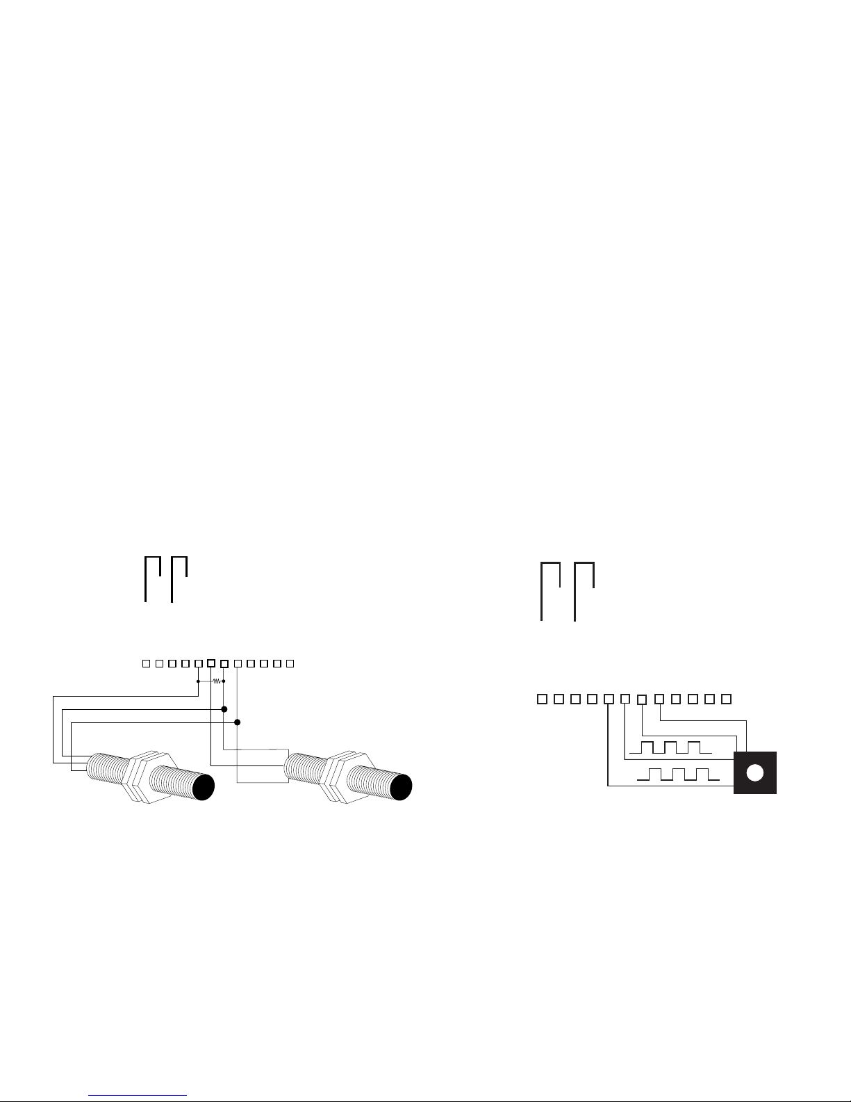
CONNECTING SENSOR INPUTS
These diagrams show how to hook typical input sensors to the unit. The unit supplies an unregulated 12 Volt (50mA)
output to power these sensors (Pin 7).
A valid pulse is one which makes a transition from the off-state (0 to 1V) to the on-state (4 to 30V): a positive going edge.
The input impedance is 10K Ohms to ground. The unit can be programmed from the front panel for slow switch closure
inputs up to 40Hz (select "Lo CPS"), or solid state switches (select "hi CPS") up to 9.99KHz. No rear terminal jumpers are
required. Use PNP (sourcing) type pulsers.
TYPICAL SENSOR HOOKUP TYPICAL QUADRATURE HOOKUP
When the unit has the quadrature input, the counter must
be set at:
A net B, A sub B (for "set to preset", A add B) and the
scaling factors for A & B must be of equal value.
5

WHAT CAN YOU VIEW?
FUNCTION
"A" RELAY
N.C. OUTPUT
"B" RELAY
N.C. OUTPUT
"A" PRESET
TRANSISTOR (NPN)
"B" PRESET
TRANSISTOR (NPN)
"B" AS BATCH
COUNTER
"B" AS GRAND
TOTAL COUNTER
MODIFICATION
CUT JUMPER
AT "A" "B" TO "2"
CUT JUMPER
AT "D" "E" TO "4"
CUT JUMPER
AT "A" "C" TO "2"
CUT JUMPER
AT "D" "F" TO "4"
SELECT JUMPER
"A SEP B" "H" TO "G"
SELECT CONNECT
"A SEP B" PULSES TO
"A" & "B"
BOTTOM VIEW AT TERMINAL
DE
G
H
20192
12 11 10 9 8 7 6 5 4 3 2 1
L
4
AB
2
FC
JUMPER SELECTIONS
1) "A sub B" - If you have selected the "A sub B" mode, pressing "view" shows:
A) The net result of subtracting input B from input A. Pulses on input B will subtract (count down). Pulses on input A
will add (count up) if "reset to 0" is selected, if "set to preset" is selected, input A will subtract (count down).
B) The rate of input A.
2) "A add B" - If you have selected "A add B" mode, pressing "view" shows:
A) The net result of adding "A" and "B" inputs. Pulses on input B will add (count up). Pulses on input A will add
(count up) if "reset to 0" is selected, if "set to preset" is selected input A will subtract (count down).
B) The rate of input A.
3) "A sep B" - If you have selected " A sep B" mode, pressing "view" shows:
A) The total counts of input A. If "reset to 0" is selected A counts up, if "set to preset" is selected A will count down.
B) The rate of input A.
C)* The total counts of input B. B will always count up.
NOTE: In "A sep B" mode, B can be used in 3 ways:
1) As a separate totalizing counter
2)** As a Batch Total Counter for input A
3)** As a Grand Total Counter for input A
NOTE:
* All decimal points are inverted when "B total" is being displayed.
** See below on how to modify for Batch Count and "B" as a Grand Total Counter.
OUTPUT JUMPER SELECTIONS
*
*
MILLIVOLT INPUT OPTION
JUMPER SELECTIONS
J3
C5
C1
U1
P1
U6
C2
REV
20229
J6
J5
J2
J1
J4
B
U3
CR2
C3
CR5
C8R7R5
C7
R1
R10R6C6
R8
U5
U4
C4
C9
CR6
CR3
R2
R9
U2
R3
CR4
CR1
R4
If the unit has the millivolt input bd.# 20229, A & B inputs can be
separately solder jumper programmed to accept either a low millivolt
or 4-30 V input. Each unit shipped is programmed according to part
number. If solder jumpers are made, the part number should be
modied to reect the changes made
C=CLOSE, O=OPEN
* The unit must be removed from the case to access jumpers C & F, all
other jumpers can be accessed by removing the plastic extender.
NOTE: All three pads at jumpers 2 and 4 are connected.
4-30V INPUT Millivolt INPUT
Input A J1-O, J2-C, J3-O J1-C, J2-O, J3-C
InputB J4-O, J5-C, J6-O J4-C, J5-O, J6-C
6

PROGRAMMING FLOWCHART
ENTER
65
4
3
21
LOCK PRE A PRE BVIEW PRGM
ENTER
Press to "reset"
in operating
mode.Press to
"enter" in
programming
mode.
Press to enter
lock code for
panel lock.
Press to
view or
change
preset A.
Press to
view or
change
preset B.
Press to alternately
view A rate & net
total or A rate,
A total & B total.
Press to cycle
through PROGRAM
choices. Press to
toggle between
choices in program
mode.
OPERATING THE FRONT PANEL
RST
PRGM
FACToR
RUN MODE
DP F A
#####
DP F B
#####
ENTER
ENTER
ENTER
ENTER
ENTER
PRGM
Hi
CPS
Lo
CPS
PRGM
RUN MODE
ENTER
RATE METER
(MR2) ONLY
CouNT
ENTER
RST
0
SET
PR
PRGM
ENTER
DPLoC
ENTER
A
NET
B
A
SEP
B
PRGM
ENTER
ENTER
A
ADD
B
A
SuB
B
PRGM
Hi
CPS
Lo
CPS
PRGM
ENTER
RUN MODE
ENTER
RATE
ENTER
SCALE RPS
PRGM
Z3600
Z60
PRGM
ENTER
ENTER
ENTER
RUN MODE
NoR ##
ENTER
FiguR#
ENTER
DLY #
ENTER
LoC
ENTER
LC
PRg
LC
ALL
PRGM
ENTER
CoDE
#####
RUN MODE
ENTER
RELAY
ENTER
A
ToT
A
RATE
PRGM
A ##.#
ENTER
ENTER ENTER
B
ToT
B
RATE
PRGM
B ##.#
ENTER
ENTER ENTER
RUN MODE
PRGM PRGM
PRGM
NOTE: Several programming selections will not appear with MC2 and MR2 units.
Start Here
Press this key to step through menu choices.
RST
Press this key to enter displayed value
7

The following is a list of abbreviations as they appear on the display and front panel of the unit.
ABBREVIATION DESCRIPTION
FACTOR SCALING FACTOR - For A and B Inputs. Each input has a separate 5 digit dividing scale factor.
DP F A DECIMAL POINT FOR FACTOR A - Enter location of decimal point for scaling Factor A by pressing the
button under the digit where the decimal is desired.
DP F B DECIMAL POINT FOR FACTOR B - Enter location of decimal point for scaling Factor B by pressing the
button under the digit where the decimal is desired.
COUNT PORTION OF MENU FOR SETTING COUNTER VARIABLES
RST 0 RESET TO 0 - Counter will reset to 0. Input A will count up from 0. Input B will subtract (count down) in A
Sub B mode. Input B will add (count up) in A Add B mode.
SET PR SET TO PRESET - Counter will reset to preset A. Input A will count down from preset A. Input B will count
up (add) in "A add B" mode and input B will count down (subtract) in "A sub B" mode.
DP LOC DECIMAL POINT LOCATION - Enter desired location of decimal by pushing the button under the digit where
the decimal is desired. Changing the decimal will change the decimal location in the A & B counters as well
as the rate display.
A NET B NET RESULT OF ADDING OR SUBTRACTING A & B INPUTS
A SEP B A & B INPUTS ARE SEPARATE - A & B are not added or subtracted.
A SUB B A SUBTRACT B - The number of scaled pulses from Input B are subtracted from the number of scaled pulses
from Input A. (-99999 TO 999999)
A ADD B A ADD B - The number of scaled pulses from the A Input are added to the number of scaled pulses from the
B Input.
HI CPS HIGH COUNTS PER SECOND - This sets the unit for high count speeds (0-9.99KHz)
LO CPS LOW COUNTS PER SECOND – This sets the unit for contact debounce ltering (0-40Hz)
RATE PORTION OF MENU FOR SETTING RATE VARIABLES
RPS RATE PER SECOND - The display will read in rate per second.
SCALE SCALING - Allows unit to display rate per minute or rate per hour.
Z 60 DIVIDE K FACTOR BY 60 - This sets the unit for rate per minute; equal to 60 times rate per second.
Z 3600 DIVIDE K FACTOR BY 3600 - This sets the unit for rate per hour; equal to 3600 times rate per second.
NOR## NORMALIZING FACTOR - Normalizes (averages) the data being received. Higher settings provide more
normalizing (averaging) for a more stable display. Derived from the equation:
(Old Data x "NOR" + New Data)
("NOR" + 1)
FIGUR ## SIGNIFICANT FIGURE - This sets the amount (1-5) of meaningful gures the unit will display. (RATE DIS
PLAY ONLY). FOR EXAMPLE: If "2" is set as the gure, a rate of 273.45 will be displayed as 270.
DLY## DELAY FACTOR - The amount of time (02 to 24 sec.) the unit will "look" for valid data, before the display
defaults to zero. (RATE DISPLAY ONLY)
8

LOC LOCK - This portion of the menu allows you to:
1 2 3 4
REAR VIEW
1 2 3 4 5 6 7 8 9 10 11 12
13 14
Analog Out Setup SwitchesSerial Port
ON
1- COMMON
2- N.O.(N.C./NPN)
3- COMMON
4- N.O.(N.C./NPN)
5- A INPUT
6- B INPUT
7- 12VDC OUT/+DC IN
8- -DC (GROUND)
9- RESET INPUT
10- NOT USED
11- A.C. INPUT
12- A.C. INPUT
SYALER
A
B
13- V+
14- I SINK
GOLANA
TUPTUO
ON
CAL.
0-20mA
COUNT
SET
OFF
RUN
4-20mA
RATE
RUN
4 3 2 1
NO
HCTIWS
1) lock the program (presets are still accessible)
2) lock all (presets and program are locked).
LC PRG LOCK PROGRAM - This will lock the program and allow the presets to be changed when the unit is in the
lock mode.
LC ALL LOCK ALL - This will lock the program and the presets when the unit is in the locked mode. The presets can
be viewed, but not changed.
CODE LOCK CODE - This message (code) will ash on display for approximately 3 seconds. It will be followed by a
5 digit number (xxxxx). The number you enter here will be the code to lock and unlock the unit.
RELAY RELAY - This portion of the menu allows you to set your relay operation variables.
A TOT RELAY A FOR TOTALIZER - When this is selected relay A will activate when the net total has reached
Preset A ("A NET B" Mode ). Relay A will activate when the total of input A reaches preset A ("A SEP B"
Mode).
A RATE RELAY A FOR RATE - When this is selected relay A will activate when the Rate of input A equals or exceeds
preset A when in "A NET B" or "A SEP B" mode. The relay will drop out when the rate of A falls below preset
A.
A##.# RELAY A DURATION - This message will appear when "A TOT" is selected. It is the duration which the
relay will remain energized (00.1 to 99.9 sec). If 00.0 is selected, the relay will latch until reset. When the
duration is not at 00.0, the unit will autorecycle.
B TOT RELAY B FOR TOTALIZER - When this is selected relay B will activate when the net total has reached preset
B ("A NET B" Mode). Relay B will activate when the total of input B has reached preset B ("A SEP B" Mode).
B RATE RELAY B FOR RATE - When this is selected relay B will activate when the rate of input A equals or exceeds
preset B when in "A NET B" or "A SEP B" mode. The relay will drop out when the rate of A falls below preset
B.
B##.# RELAY B DURATION - Follow same procedure as A ##.#.
MINITROL TERMINATIONS
9

CALCULATING SCALE FACTORS
There are two separate dividing scale factors, one for input "A" and one for input "B". The factor to enter is the number of
pulses per the desired unit of measurement. The factor ranges from 0.0001 to 99999. The factor is the same for rate and
count on input "A". Because the "units per second", "minute", or "hour" are eld programmable from the keypad, scale factor
calculations for the ratemeter are easy. Here are some examples:
SCALING FACTOR EXAMPLES:
BATCHING: You want to count the number of batches (10 boxes each) being loaded onto a pallet.
Solution - Dial in a scale factor of 10.
UNIT COUNTING: You pick up a notch on a paper roll (1 pulse per shaft revolution). Each revolution equals 3 feet. To
nd the number of pulses per foot, simply divide "1 pulse" by "3 feet" (1÷ 3 = .3333).
Solution - One foot equals 0.3333 pulses, enter this as the scale factor and the display will read in feet.
RATE: The shaft of a motor has a ywheel with 10 spokes. The KEP DO series prox switch is mounted to
sense 10 pulses per revolution. RPM of the shaft is the desired readout.
Solution: Enter a Factor of 10 and for every 10 pulses, "1" will appear on the display. Set rate per
second, minute or hour as desired.
A conveyor carrying bottles must be controlled for bottle speed. For each revolution of the front roller, three bottles
travel by. Thus, one revolution equals 3 bottles. A wheel with seven spokes is mounted on the roller. The user
can't sense bottles because they are traveling through a washer, so a sensor is placed at the roller, sensing seven
pulse per revolution of the shaft, which equals 3 bottles per revolution.
To calculate the scale factor (7 ppr ÷ 3 bottles) = 2.3333 scale divider. Set rate per second, minute or hour as
desired.
A ow meter is generating 52.6 pulses per gallon. The desired readout is in liters. Since there are 3.785 liters per
gallon, divide 52.6 by 3.785 to nd the number of pulses per liter (52.6 ÷ 3.785 = 13.897).
Enter 13.789 as the scale factor so the display will read in liters.
An aluminum sheeting plant has a cut to length application to customer specication. A ten pulse per revolution
encoder with a 12" wheel is used to sense. The travel of aluminum sheets is in inches. Thus, after 10 pulses, you
want 12 to appear on the display. Thus, 10 ÷ 12 = .8333. Enter .8333 as your scale factor.
10

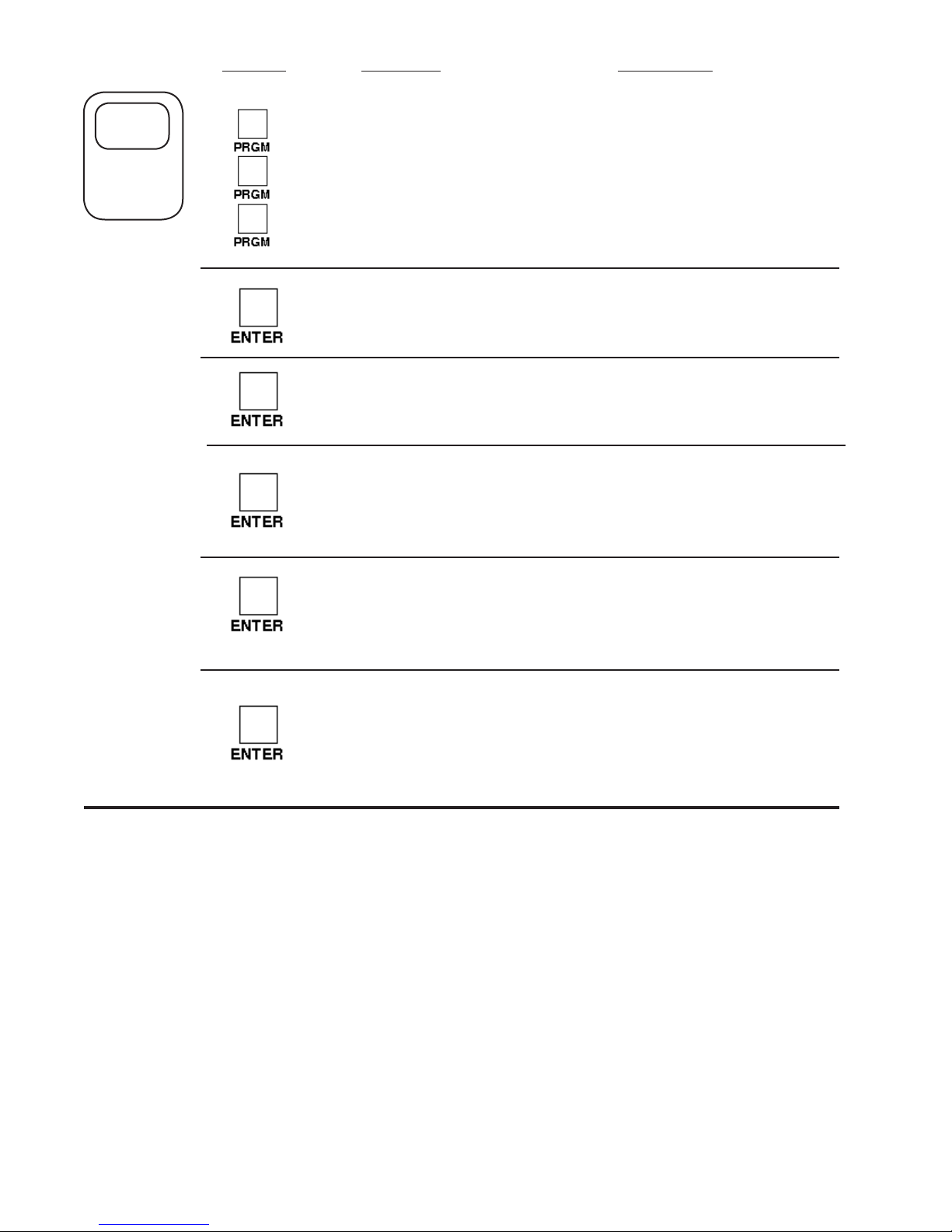
PROGRAMMING
STEP
1
SETTING
SCALING
FACTORS
THIS SECTION
WILL ONLY
APPEAR IN THE
RATE METER
ONLY VERSION
PRESS
DISPLAY
factor
dp f a
#####
hi cps
or
lo cps
REMARKS
This section of the menu is used to set
up the scaling factors for inputs A & B.
This sets the decimal for factor A. Press
the arrow key under the digit where
the decimal is desired. To clear the
decimal, press the arrow key furthest
to the right (PRGM) .
This is the scaling factor for input A.
To change, press the arrow key under
the digit(s) to change. Press ENTER
to enter the displayed value.
This section will only appear in the
RATE only version. Press the PRGM
key to choose HIGH CPS (0-9.99KHz)
or LOW CPS (0-40Hz). Press the EN-
TER key to enter the displayed choice.
dp f b
#####
This sets the decimal for factor B. Press
the arrow key under the digit where
the decimal is desired. To clear the
decimal, press the arrow key furthest
to the right (PRGM) .
This is the scaling factor for input B.
To change, press the arrow key under
the digit(s) to change. Press ENTER
to enter the displayed value.
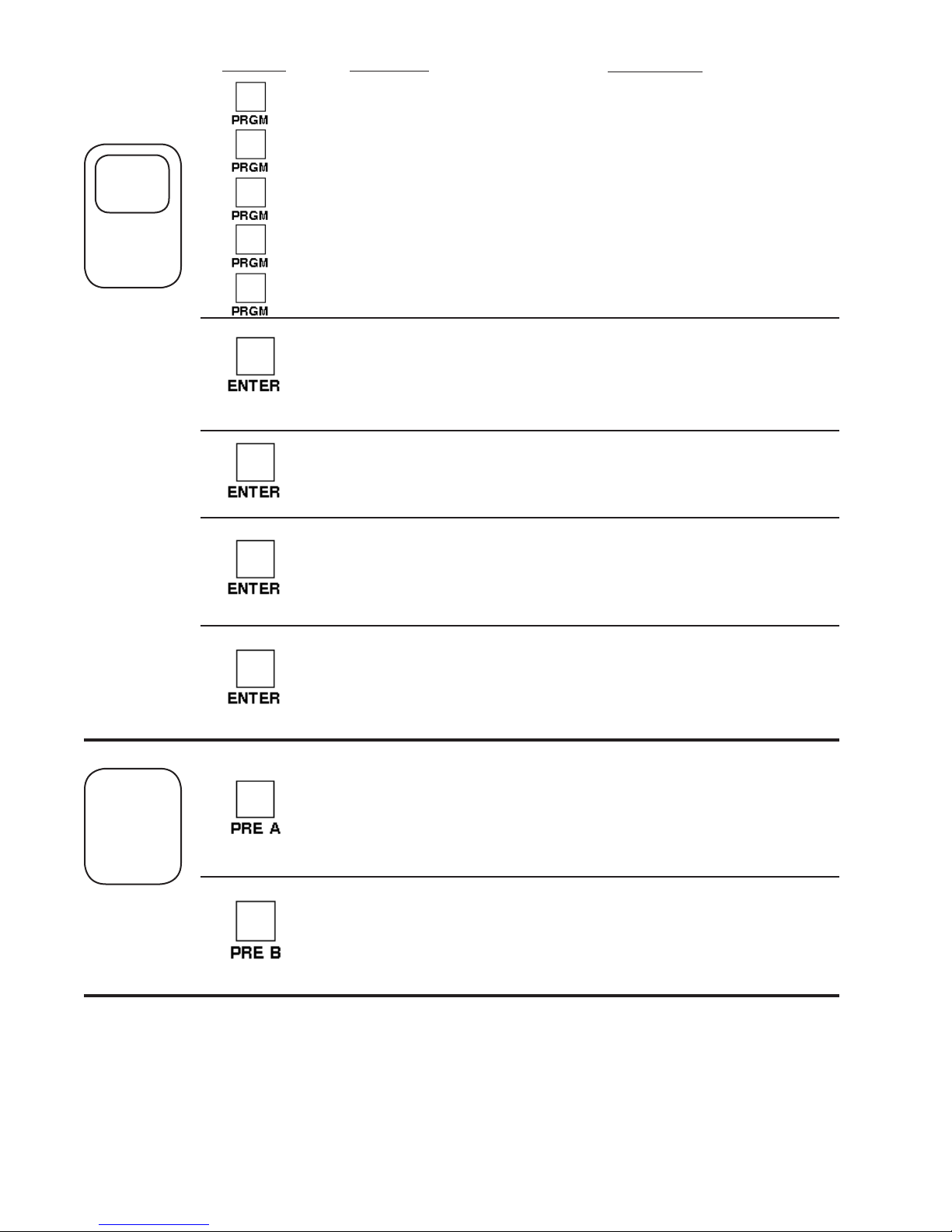
11

PRESS DISPLAY REMARKS
factor
STEP
2
SETTING
THE
COUNTER
count
rst 0
or
set pr
dp loc
a net b
or
a sep b
This section of the menu sets up the
counter information.
Press the PRGM key to choose RST 0
(reset to 0, count up) or SET PR (set to
preset, count down), press the ENTER
key to enter the displayed choice.
This sets the decimal location for the
A & B counters. Press the arrow key
under the desired digit location. To
clear the decimal, press the arrow key
furthest to the right. Press the ENTER
key to enter the displayed location.
Press the program key to choose A
NET B (add or subtract A & B) or A SEP
B (view A & B as separate counters).
Press the ENTER key to enter the
displayed choice.
a sub b
or
a add b
hi cps
or
lo cps
This section will only appear if A NET
B was selected. Choose A SUB B (A
subtract B) or A ADD B. Press the EN-
TER key to enter the displayed choice.
Press the PRGM key to choose HIGH
CPS (0-9.99KHz) or LOW CPS (0-
40Hz). Press the ENTER key to enter
the displayed choice.
12
STEP
3
REMARKSPRESS DISPLAY
factor
SETTING
THE RATE
count
rate
rps
or
scale
z 60
or
z 3600
nor ##
figur #
This section of the menu is used to set up
the rate information.
Press the PRGM key to choose RPS (rate
per second) or SCALE (RPM, RPH). Press
ENTER to enter displayed choice.
Press PRGM to choose ÷60 (RPM) or
÷3600 (RPH). Press ENTER to enter dis-
played choice.
This sets the normalizing (averaging) factor.
Press the arrow keys under the desired
digits to change. Press ENTER to enter
displayed value.
This sets the number of signicant gures
to be displayed. Press the arrow key under
the digit to change. Press ENTER to enter
displayed value.
dly #.#
This sets the delay time (2 to 24 sec.) that
the unit will "look" for valid input data before
the display falls to 0. Press the arrow key
under the digits to change. Press ENTER
to enter displayed value.
13

PRESS
DISPLAY REMARKS
STEP
4
SETTING
LOCK
factor
count
rate
loc
LC PG
or
LC ALL
CoDE
Flashes
followed by:
#####
This section of the menu is used to set up the
lockout type and code.
LC PG = Locks program but presets and re-
set are accessible.
LC ALL= Locks entire keypad.
Press the PRGM button to toggle between
choices; Press ENTER to enter displayed
choice.
After CODE ashes the display will show the
existing lock code. To change the code press
the key under each digit to be changed. Press
ENTER to enter displayed value.
SETTING
THE
LOCK
STATUS
CoDE
Flashes
followed by:
0
LoC
or
uN LoC
Key in the lock code (see programming step
4) by pressing the keys under the digits to be
changed. Press the ENTER key to enter the
displayed code.
After the code is entered the unit will display
LOC (unit is locked) or UN LOC (unit is unlocked). This message will be displayed for
approximately 3 seconds before the unit returns to the run mode.
14
DISPLAYPRESS
factor
REMARKS
STEP
5
SETTING
THE
RELAYS
count
rate
loc
relay
a tot
or
a rate
A ##.#
b tot
or
b rate
This section sets up the relay information.
Press the PRGM key to choose A TOT (A
assigned to total) or A RATE (A assigned to
rate). Press enter when the desired choice is
displayed.
This is the duration (.1 to 99.9 sec) that relay
A will remain energized. If 00.0 is selected,
the relay will latch until reset
Press the PRGM key to choose B TOT (B
assigned to total) or B RATE (B assigned to
rate). Press enter when the desired choice is
displayed.
SETTING
THE
PRESETS
b ##.#
PRE A
Followed by
last PRE A
entered
PRE B
Followed by
last PRE A
entered
This is the duration (.1 to 99.9 sec) that relay
B will remain energized. If 00.0 is selected,
the relay will latch until reset
PRE A = Preset A (Final Preset); The set point
at which output A will trigger. If the displayed
value is not the desired preset, press the
key(s) under the digit to be changed.
PRE B = Preset B (Prewarn); The set point
at which output B will trigger. If the displayed
value is not the desired preset, press the
key(s) under the digit to be changed.
15
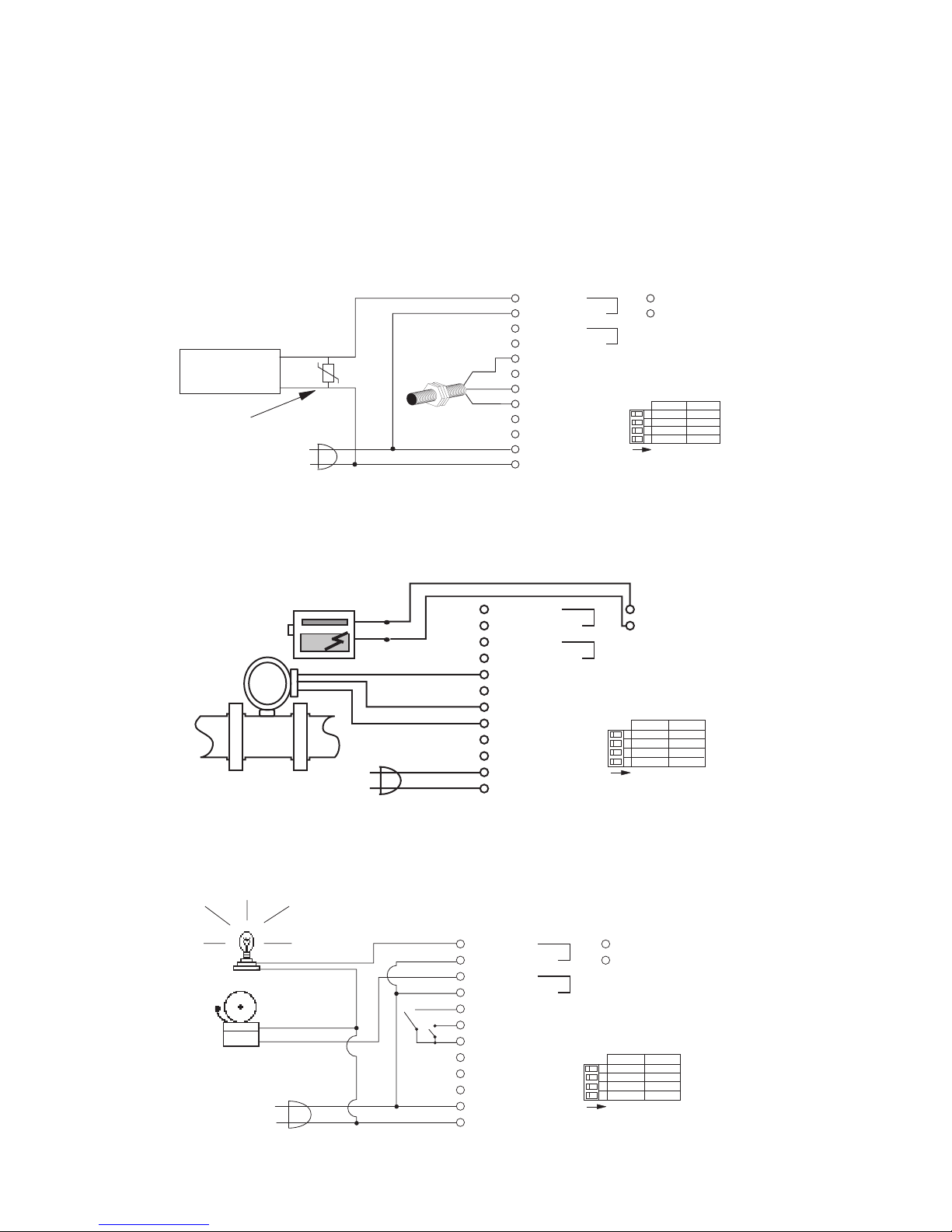
OUTPUT WIRING
The following diagrams detail the connection of the relay and analog output options. Each relay consist of a form A contact
(Normally Open). NPN transistor or Normally Closed contacts are available with solder jumpers (see Jumper Options).
SOLENOID (Single Stage)
Use Relay A (pins 1 & 2) for single stage preset. When the count or rate (selectable) reaches Preset A, Relay A will
energize. When Relay A closes, current passes through the solenoid for activation. When operating AC solenoids,
we recommend the use of an MOV to reduce inductive kickback (use a diode for DC solenoids).
A
B
HCTIWS
SYALER
NO
13- V+
14- I SINK
OFF
4 3 2 1
RUN
4-20mA
RATE
RUN
TUPTUO
ON
CAL.
0-20mA
COUNT
SET
GOLANA
SOLENOID
MOV
recommended
D08P
Prox Sensor
BLK
BRN
BLU
1- COMMON
2- N.O.(N.C./NPN)
3- COMMON
4- N.O.(N.C./NPN)
5- A INPUT
6- B INPUT
7- 12VDC OUT/+DC IN
8- -DC (GROUND)
9- RESET INPUT
10- NOT USED
11- A.C. INPUT
12- A.C. INPUT
ANALOG OUTPUT
The analog output can be selected to output 4-20 mA or 0-20 mA and can be selected to track the rate or count.
Pin 13 supplies 12 to 18V to power the current loop. Pin 14 supplies the current sinking driver. When connecting
a strip chart recorder, make connections as follows:
STRIP CHART
ANALOG
RECORDER
TURBINE FLOWMETER
+
-
PULSE OUTPUT
+12V
GND
1- COMMON
2- N.O.(N.C./NPN)
3- COMMON
4- N.O.(N.C./NPN)
5- A INPUT
6- B INPUT
7- 12VDC OUT/+DC IN
8- -DC (GROUND)
9- RESET INPUT
10- NOT USED
11- A.C. INPUT
12- A.C. INPUT
RELAYS
A
B
SWITCH
ON
13- V+
14- I SINK
OFF
RUN
4-20mA
RATE
RUN
1 2 3 4
OUTPUT
ON
CAL.
0-20mA
COUNT
SET
ALARMS
The relays can be used to trigger alarms which warn the operator that a batch is complete or the rate has
exceeded a set speed. The outputs are programmable to be assigned for rate or count. When assigned to the
count, the relays can have a user selectable on time (duration) or can be latched until reset.
LIGHT
BELL
1- COMMON
2- N.O.(N.C./NPN)
3- COMMON
4- N.O.(N.C./NPN)
5- A INPUT
6- B INPUT
7- 12VDC OUT/+DC IN
8- -DC (GROUND)
9- RESET INPUT
10- NOT USED
11- A.C. INPUT
12- A.C. INPUT
16
A
B
HCTIWS
SYALER
NO
13- V+
14- I SINK
OFF
4 3 2 1
RUN
4-20mA
RATE
RUN
TUPTUO
ON
CAL.
0-20mA
COUNT
SET
GOLANA

ANALOG OUTPUT OPTION
1 2 3 4
REAR VIEW
1 2 3 4 5 6 7 8 9 10 11 12
13 14
Analog Out Setup SwitchesSerial Port
ON
Description:
An optional 4-20mA (0-20mA) output has been added to the Minitrol
series. The output can be programmed to track rate or total. This
feature is available by adding sufx A to the part number. Connec-
tions are via a 2 terminal pluggable screw connector.
Connections: (see FIG. 1)
PIN13 supplies the 12 to 18 VDC to power the current loop.
PIN14 is the control sink driver
Accuracy:
50uA worst case
Compliance Voltage:
3 to 30 VDC non conductive
Setup:
The optional analog output feature uses 4 dip switches on the back
for setup. These switches are used as follows:
SW1 - View or change "set low" and/or "set high" values
SW2 - Select output for rate or total
SW3 - Select 4-20mA or 0-20mA
SW4 - Calibrate the unit.
After the regular parameters shown in the programming owchart
have been set, locate the 4 switches on the back of the unit. (see
FIG. 1)
SWITCH 4: Calibrate (normally off)
Switch 4 is used for calibration. Calibration is done at the factory
and should not be needed (see SWITCH 1 to enter high and low
values). If recalibration is desired, a calibrated 20mA ammeter with
1uA resolution is needed. Attach the "+" lead of the meter to pin
13 and the "-" lead to pin 14. Set switch 4 ON (up). The unit will
output approximately 20.000mA and a decimal will light in the third
position. Read the output using the ammeter. Press PRE A. If the
display is the same as the ammeter reading, press ENTER. If not,
press buttons A through E to step to ammeter reading and ENTER.
(Disregard display which now shows the last count reading with decimal point in third position) Return switch 4 to OFF (down) position.
RS232 & RS422 Operation:
When the unit is suppled with RS232 or RS422, the analog output
"low" and "high" settings can be accessed and changed through the
serial port. The codes are as follows:
AL Unit will display (transmit) analog out "low" value.
AL(S)XXXXX Unit will load analog out "low" with entered
number. (S) = space
AH Unit will display (transmit) analog out "high" value.
AH(S)XXXXX Unit will load analog out "high" with entered
number. (S) = space
FIG. 1
Switch Settings:
SWITCH 1: Enter Analog Low & High (normally off)
Switch 1 is used to load in the low (4mA or 0mA) and/or the high
(20mA) output settings. With power on, set switch 1 ON (up).
LOW SETTING is viewed or changed by pressing PRE A. If the
displayed value is correct, press ENTER. If not, press buttons A
through E to step to the desired value and press ENTER. (disregard
the display which will show the last count reading).
HIGH SETTING is viewed or changed by pressing PRE B. If the
displayed value is correct, press ENTER. If not, press buttons A
through E to step to desired value and press ENTER.
Return switch 1 to OFF (down) position, PRE A and PRE B buttons
now function to view or change relay trip values.
SWITCH 2: Select Count or Rate
SW2 OFF (down): Analog output follows rate
SW2 ON (up): Analog output follows count
SWITCH 3: Select 4-20mA or 0-20mA
SW3 OFF (down): Selects 4-20mA output range
SW3 ON (up): Selects 0-20mA output range
Typical Wiring:
RELAY A COMMON
RELAY A N.O.
RELAY B COMMON
RELAY B N.O.
INPUT A
INPUT B
12 to 18V OUT/ +DC IN
-DC (GROUND)
RESET INPUT
NOT USED
110 / 220 VAC
110 / 220 VAC
12 to 18V OUT
ANALOG OUT (SINK)
10
11
12
13
14
1
2
3
4
5
6
7
8
9
PULSE OUTPUT
+12V
GND
TURBINE FLOWMETER
+
-
STRIP CHART
RECORDER
17

INTERFACE CARD RS 232/422 OPERATION
RS 232/422 SET-UP:
All serial communication mode changes must be done
through serial communications. Mode changes cannot be
done through the front panel. The unit is set at factory to:
9600 baud rate,"MARK" parity and device number 01. To
enter the program mode you must set your terminal for 9600
baud rate and "MARK" parity. Next, type D1(s), (s)= space
bar. The unit will echo back "DEVICE #1:". Now type EP
(enter program) and a carriage return (enter). The unit will
echo back "PROGRAM SETTING". You are now in the programming mode. To initialize the unit (reset defaults), place
a jumper between pin 7(+12V )[bottom board] and pin 1(init)
[DB -9 connector] on initial power up. The unit defaults to:
300 baud rate,"MARK" parity and device number 01.
SETUP PROCEDURE:
The following sections consist of the communications setup
options as they appear in the menu. (If you wish to exit the
program mode, at any time you can hit the "escape key" (Hex
Code: 1B) and the unit will save the changes made but not
effect the remaining data values.) When each section of the
setup menu is displayed, the current data will appear in the <
> signs. If you wish to change the data, type in the number
of the desired choice and press return (enter). If you wish to
keep the current data, simply press return.
DEVICE NUMBER:
Each unit in the hook-up must be assigned it's own device
number (1 to 99). Zero is reserved for a dedicated hook-up
to only one terminal, and it's transmit output line remains in
an "on" active state. The device number is entered in the
program mode. The unit will prompt you:
DEVICE# <XX>?
If XX is the desired device number press return (enter), if not
enter the desired number after the question mark and press
return (enter).
BAUD RATE:
The baud rate is the speed at which data is transmitted,
expressed in bits per second. Baud rates of 300, 600, 1200,
2400, 4800 or 9600 are available. The unit is set to 9600
baud rate when it ships from the factory. When in the baud
rate section of the menu, the unit will list :
BAUD RATES:
1:300 2:600 3:1200
4:2400 5:4800 6:9600
then prompt you:
BAUD RATE <9600>?
Press return (enter) if this is the desired baud rate or enter
the assigned number of one of the six possible baud rates.
If an invalid baud rate is entered the unit will prompt you to
choose another baud rate. This will occur until a valid baud
rate is entered or escape is pressed.
PARITY:
Parity is a bit of information that is inserted before the stop
bit and is used to help check if the transmission is correct.
When setting the parity you may select "ODD" (parity bit is
logic 0 if total number of logic 1's in the rst seven data bits is
odd), "EVEN" (parity bit is logic 0 if total number of logic 1's in
the rst seven data bits is even), "MARK" (parity bit is always
logic 1 - High / Mark) or "SPACE" (parity bit is always logic 0 -
Low / Space). If a "MARK" parity is chosen, it will appear that
two stop bits are used. Use the "MARK" parity with terminals
using parity "OFF" or "NONE". These terminals ignore the
parity. The unit does not check the parity but does transmit
the parity chosen. When setting the parity, the unit will print:
PARITIES:
MARK-0 SPACE-1 EVEN-2 ODD-3
Then the unit will prompt you:
PARITY<MARK>?
If this is the desired parity press return (enter), if it isn't enter
the number of the desired parity then press return (enter).
STROBE LIST:
The serial interface card is also equipped with a strobe line.
When the strobe line is triggered, a chosen set of data will
be transmitted to be displayed or printed. The selections for
the display list are entered in the program mode. Enter "1"
to add selections to the list and enter "0" to delete selections
from the list. The seven available items for the strobe display
list are: (1) Preset A, (2) Preset B, (3) K-Factor A, (4) K-Factor B, (5) Rate of A, (6) Count A, (7) Count B. In the "A net
B" mode Count A will display the Net Count and Count B is
an invalid command and the unit will transmit useless data.
When setting the strobe list the unit will print :
ENTER STROBE LIST:
DO NOT DISPLAY-0 DISPLAY-1
The unit will prompt you:
PRESET A<DISPLAY>?
PRESET B<DISPLAY>?
K-FACTOR A<DISPLAY>?
K-FACTOR B<DISPLAY>?
RATE<DISPLAY>?
COUNT A<DISPLAY>?
COUNT B<DISPLAY>?
If the above choices are entered, when the strobe line is triggered (3-30V positive pulse) the unit will transmit:
DEVICE# 1:
PA XXXXX
PB XXXXX
KA XXXXX
KB XXXXX
DR XXXXXX
DA XXXXXX
DB XXXXXX
(SEE COMMANDS BELOW FOR DESCRIPTION OF COMMAND CODES).
Each time the strobe line gets triggered the unit will transmit
this data unless the program mode is entered and the strobe
list altered.
After these four items have been entered they will remain
unaltered unless the program mode is entered again and the
values changed. The unit is now set and must be addressed
by it's device number to come on line again.
18

SERIAL INPUT COMMANDS:
To get a unit on line you must address it by it's device number.
This is done by typing DXX(S), XX= device number. The unit
comes on line and echoes back DEVICE# XX. Insure that
"DEVICE# XX:" is received before requests are sent. The unit
is now ready to receive a command or string of commands
separated by a space. A carriage return (enter) will enter the
commands and processing of requests begins. The carriage
return (Hex Code "D") puts the unit "off line" after data is
processed.
COMMANDS:
EP...........Unit will enter program mode.
DA..........Unit will display (transmit) Count A.
DB..........Unit will display (transmit) Count B.
DR..........Unit will display (transmit) rate A.
KA..........Unit will display K-factor A.
†*KA(S)XXXXX....Unit will load K-factor A
with entered number.
KB..........Unit will display K-factor B
†*KB(S)XXXXX....Unit will load K-factor B
with entered number.
PA...........Unit will display Preset A.
†PA(S)XXXXX....Unit will load Preset A with
entered number.
PB...........Unit will display Preset B
†PB(S)XXXXX....Unit will load Preset B with
entered number.
RA..........Counter A will reset
†*RA(S)XXXXXX...Unit will set Counter A to
entered number.
RB..........Counter B will reset.
†*RB(S)XXXXXX...Unit will reset Counter B to
entered number.
*THE UNIT WILL RECOGNIZE A DECIMAL IF ONE IS
PLACED IN ANY OF THESE DATA VALUES.
†THE UNIT WILL ONLY RECOGNIZE THE LAST FIVE
DIGITS ENTERED (SIX DIGITS FOR RA & RB).
The following is an example of requests and responses:
Transmit from terminal Receive from unit
(s)=Space
D5(s) [Unit #5 Activated] DEVICE# 5:
PA(s)12345(s)PA PA 12345 PA
KA(s)1576(s)KA KA 1576 KA
KB(s)6751(s)KB KB 6751 KB
RA(s)RB[RETURN] RA RB
(UNIT PRESETS AND A & B K-FACTORS ARE SET AND
BOTH COUNTERS ARE RESET)
12345
1576
6751
SERIAL INTERFACE OPERATION:
Data is received and transmitted over standard EIA RS232
or RS422 levels. Each ten bit character is made up of a
start bit, seven bit ASCII code, a parity bit and a stop bit.
Device number, baud rate, parity and strobe list are entered
in the program setup mode and will remain in memory even
if power is lost.
The input impedance of RS232 is 3KΩ to 7KΩ worst case.
The terminal addressing the unit must be capable of driving
all loads in the loop. The input impedance of RS422 is much
higher and there should be no problem driving as many as
99 units. The transmit line remains in a high impedance "off"
state until addressed. Only one unit is to be on line at a time!!!
More than one unit on line could damage the unit or destroy
the transmitted data.
When the unit is active (on line) it will operate in a full duplex,
echo back mode, so that data sent from the terminal will be
transmitted back for verication. When the unit is "on line",
use the proper serial transmit commands to request data or
set a new value. Up to 80 characters of data can be linked
together and transmitted to the unit in a string as long as there
is a space between the commands. If an error is made, a
correction can be made by back spacing and retyping correct
data before the return (enter) is sent. Once a return (enter) is
sent, the unit begins processing the data and will transmit the
requested data on a non-priority basis over the data transmit
line. A keypad entry or incoming data will halt the data communication cycle. Therefore, there should be a pause after
data is requested to insure that all data has been transmitted
before making another request or addressing another unit. If
the unit is not busy, it should not take longer than 300 msec to
process each request. To nd the cycle time to process and
transmit a request, calculate the bit transmit time by using this
formula: [(1÷ baud rate) x (80) + .005] x number of requests
made. This time will be extended if the unit must service
the front keypad. If transmission has not started within two
seconds after data is requested, it can be assumed that there
is a problem. The unit transmits a carriage return and line
feed after each data value. Any new communication must be
started with DXX(S) (device number and space).
RS232/RS422 - IBM-PC INTERFACE:
The following program is for IBM basic to set up RS232/
RS422 on serial port (#1) at 9600 baud. Run this program
after connecting the serial interface connections.
10 SCREEN 0,0:WIDTH 80
20 CLS:CLOSE
30 OPEN "COM1:9600,n,7,1,CS,DS,CD" AS #1
40 ON ERROR GOTO 110
50 B$=INKEY$
60 IF B$< >"" THEN PRINT #1,B$;
70 IF EOF (1) THEN 50
80 A$=INPUT$ (LOC(1),#1)
90 PRINT A$;
100 GOTO 50
110 RESUME
19
A
RST
B C
D E
ENTER LOCK PRE A PRE B VIEW PRGM
TRANSMIT A (+) PIN (2)
GROUND PIN (5)
RS 422
TRANSMIT B (-) PIN (7)
STROBE PIN (6)
+12V PIN (7)
(BOTTOM BOARD)
A
RST
B C
D E
ENTER LOCK PRE A PRE B VIEW PRGM
TRANSMIT PIN (2)
GROUND PIN (5)
RS 232
STROBE PIN (6)
+12V PIN (7)
(BOTTOM BOARD)
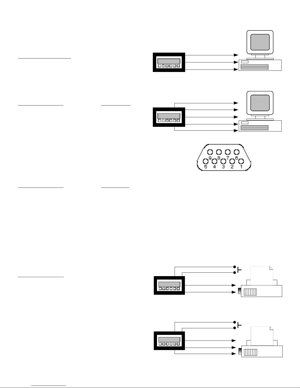
RS232 / RS422 WIRING
A
RST
B C
D E
ENTER LOCK PRE A PRE B VIEW PRGM
RECEIVE PIN (3)
TRANSMIT PIN (2)
GROUND PIN (5)
RS 232
A
RST
B C
D E
ENTER LOCK PRE A PRE B VIEW PRGM
RECEIVE B (-) PIN (8)
TRANSMIT A (+) PIN (2)
GROUND PIN (5)
RS 422
RECEIVE A (+) PIN (3)
TRANSMIT B (-) PIN (7)
COMPUTER HOOKUP:
RS 232: When connecting the unit to a computer with RS 232
communication, only three connections are needed. These
connections are: Receive data, Transmit data and Ground.
The connections should be made as follows:
DP -9 CONNECTOR COMPUTER
Transmit data (pin 2) Receive data
Receive data (pin 3) Transmit data
Ground (pin 5) Ground
RS 422: When connecting the unit to a computer with RS
422, ve connections are needed. These connections are:
Receive data A (+), Receive data B (-), Transmit data A (+),
Transmit data B (-) and Ground. The connections should be
made as follows:
DP -9 CONNECTOR COMPUTER
Transmit data A(+) (pin 2 Receive data A(+)
Transmit data B(-) (pin 7) Receive data B(-)
Receive data A(+) (pin 3) Transmit data A(+)
Receive data B(-) (pin 8) Transmit data B(-)
Ground (pin 5) Ground
PRINTER HOOKUP:
When connecting the unit to a printer, you must rst program
the desired baud rate, parity and strobe list with a computer.
After the unit is programmed it can be connected to the
printer. Connect the transmit line(s) of the unit to the receive
line(s) of the printer and be sure that both devices have
common grounds. When the strobe line is triggered the unit
will transmit the selected strobe list which you had previously
programmed.
RS 232
1. INITIALIZE
2. TRANSMIT
3. RECEIVE
4. N/C
5. GROUND
6. STROBE
7. N/C
8. N/C
9. N/C
RS 422
1. INITIALIZE
2. TRANSMIT A (+)
3. RECEIVE A (+)
4. N/C
5. GROUND
6. STROBE
7. TRANSMIT B (-)
8. RECEIVE B (-)
9. N/C
20

TROUBLESHOOTING GUIDE
PROBLEM SOLUTIONSPOSSIBLE CAUSES
Power is applied to unit but the display
does not light.
Unit works, but occasionally the display
freezes or skips counts.
Input signal is connected but the unit
does not count or display rate.
Rate is displaying: r FFFFF.
1. AC or DC power wiring is incorrect.
1. Line noise is affecting the processor
due to a current spike or surge.
1. Input wiring is incorrect.
2. Scale factors are incorrect.
3. Transmitting device is defective.
4. Wrong debounce ltering selected.
5. Minitrol is defective.
1. The unit is trying to display a
number which it can't (too small or
too large).
2. Line noise affected unit on power
up.
1. Recheck power wiring
1. Use a different power supply or
install a surge suppressor.
1. Recheck input wiring.
2. Recheck scale factors and factor
calculations.
3. Replace transmitting device.
4. Recheck debounce ltering selection
"hi cps" or "lo cps".
5. To conrm set scale factors at one
and connect a wire to pin #7 and
touch it to pin # 5 (input A). Each
time pin #5 is touched counter A
should count once. If not, call
factory for RMA. (this test will not
work on units with quadrature input)
1. Check scaling factor, if it is correct,
lower the number of signicant
gures.
2. Reprogram the unit and be sure to
enter a decimal (enter one and re
move it if a decimal is not desired).
Relays are not activating properly.
Counter resets before reaching 999999.
Various menu items are not being displayed.
1. Wrong relay duration.
2. Relay set for wrong activation
i.e. count instead of rate.
1. Relay duration is set at a value other
than 00.0. This causes the counter
to auto-reset at the preset.
1. The menu ow chart and the setup
steps show the setup for the units
with rate and total (MRT). When
using a unit which has only count
(MC2) or only rate (MR2,) several
menu items will not be displayed.
1. Recheck programmed relay duration.
2. Recheck programmed relay
activation mode.
1. If relay outputs are not being used,
set the relays for rate (MRT only).
2. Set the relay durations to 00.0.
1. The menu items which do not
appear are not used for the models
without the ratemeter (MC2) or
without the counter (MR2).
Therefore, disregard any menu items
which appear on the owchart and
setup steps, but do not appear on
the unit's display.
21

NOTE TO OUR CUSTOMER
KEP is dedicated to providing complete customer service and customer satisfaction. If
you have any comments or criticisms about how to improve this manual, please make a
note of the problem/improvement and notify us. We are always open to new ideas and
improvements. So please let us know your ideas and comments.
Call us toll free: 800-631-2165
WARRANTY
This product is warranted against defects in materials and workmanship for a period
of two (2) years from the date of shipment to Buyer.
The Warranty is limited to repair or replacement of the defective unit at the option
of the manufacturer. This warranty is void if the product has been altered, misused,
dismantled, or otherwise abused.
ALL OTHER WARRANTIES, EXPRESSED OR IMPLIED, ARE EXCLUDED,
INCLUDING BUT NOT LIMITED TO THE IMPLIED WARRANTIES OF
MERCHANTABILITY AND FITNESS FOR A PARTICULAR PURPOSE.
GARANTIE
Ce produit est garanti DEUX ANS contre les défauts du materiel et de sa construction
à partir de la date de livraison à l'achat.
La garantie est limitée à la réparation ou au remplacement du materiel, au choix
du fabricant. Cette garantie est nulle si le produit a été déterioré, mal employé ou
démonté.
TOUTE AUTRE GARANTIE EXPLICITE OU IMPLICITE, EST EXCLUE,
INCLUANT MAIS NE LIMITANT PAS A CELLE DU COMMERCE SAUF ACCORD
PARTICULIER.
 Loading...