

Kessel Pumpfix F Comfort, Pumpfix F Standard Nstructions For Assembly, Operation And Maintenance
Page 1
INSTRUCTIONS FOR ASSEMBLY, OPERATION AND MAINTENANCE
m
i
t S
i
che
r
he
i
t
ge
prüf
t
e
Qua
l
i
t
ä
t
Bauart
Bauart
geprüftgeprüft
u
ndüberwachtund überwacht
Bauart
geprüft
u
ndüberwacht
L
GA
LandesgewerbeamtBayern
KESSEL - backwater pumping station
®
Pumpfix
for wastewater with and without sewage
F Standard/Comfort
Product advantages
For wastewater with and without sewage
Backwater flap and draining pump
Simple installation in through pipes
Plug & play control unit
Control unit with self-diagnosis system
(SDS) with integrated battery back-up
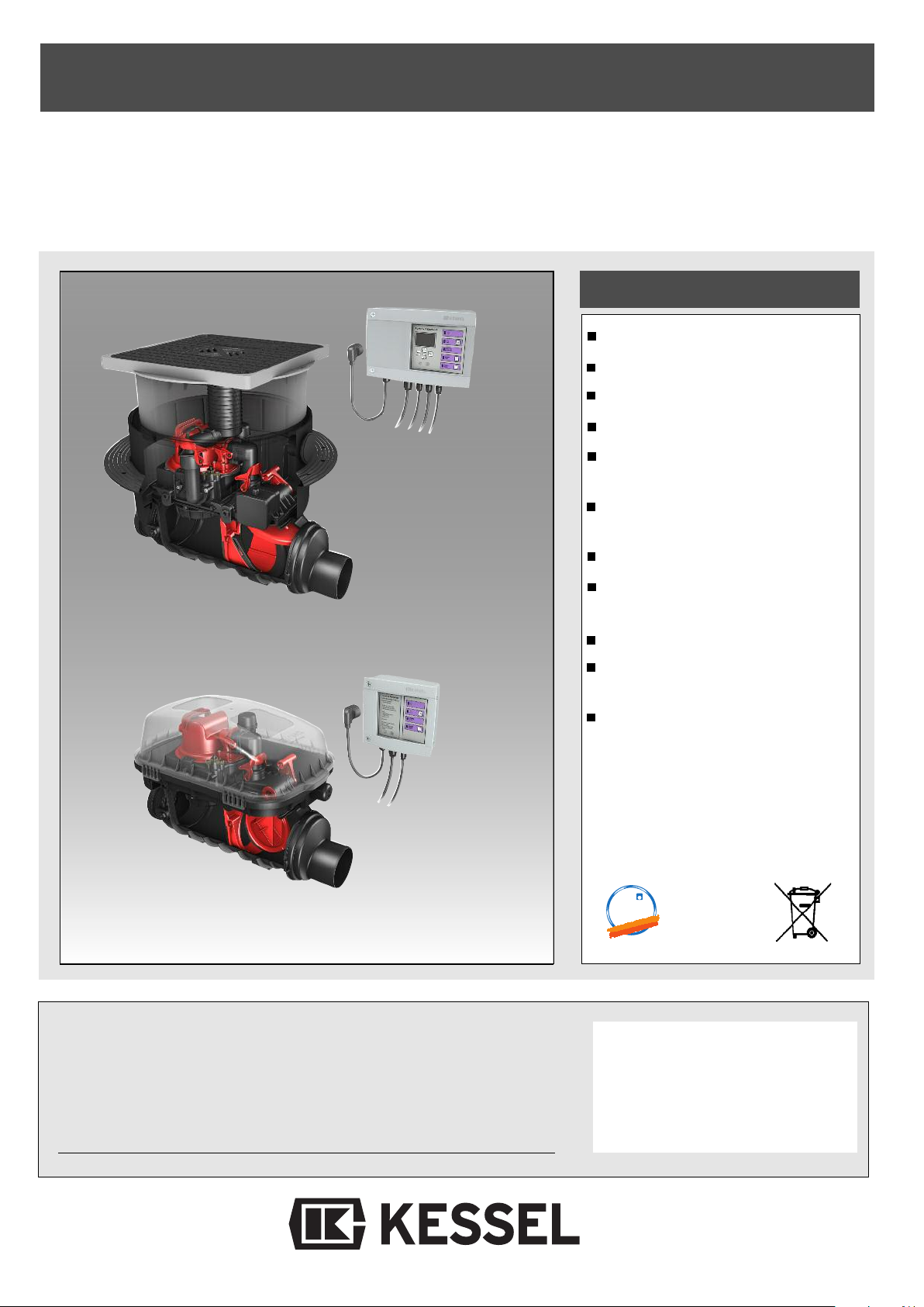
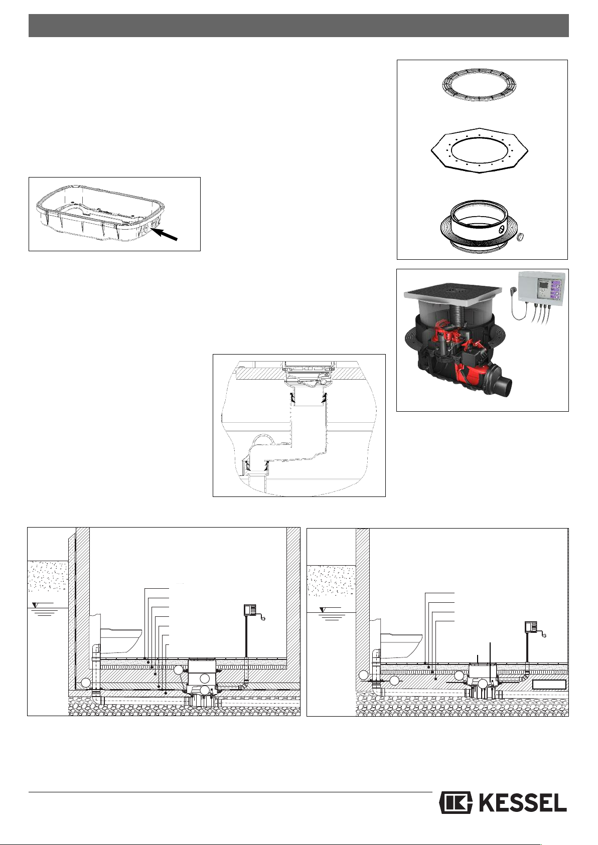
Fig. shows:
Pumpfix®F
Comfort
for installation in the
ground plate
Fig. shows:
Pumpfix®F
Standard
for installation in an
exposed pipe
Straightforward replacement of wearing
parts
Simple tool-free servicing
Additional advantages of the Komfort
version:
Control unit with display
Motor-driven locking of the backwater
flap
Integrated drain function for surface
water drainage
The installation and service of this unit should be carried
out by a licensed professional servicer
Name/Sign Date Town
Stand 04/2011
Stamp
Subject to technical amendments
ID-Number 010-843EN
Page 2
Table of contents
1. Safety instructions
2. General points
3. Installation
4. Service and maintenance
........................................................................................................... Page 2
2.1 Use ..................................................................................................... Page 3
2.2 Scope of supply .................................................................................. Page 3
2.3 Installation procedure ......................................................................... Page 3
2.4 General instructions about the installation of backwater valves ......... Page 3
3.1 Installation in the ground plate............................................................ Page 4
3.2 Recessed installation in the ground plate ........................................... Page 4
3.3 Ventilation connection ........................................................................ Page 4
3.4 Installation in an exposed wastewater pipe ........................................ Page 5
3.5 Installation in water load..................................................................... Page 5
3.6 Special features of
3.7 Set-up................................................................................................. Page 5
4.1
Service ..................................................................................................... Page 6
4.2 Maintenance............................................................................................. Page 6
4.2.1 Mounting the two covers........................................................................... Page 6
4.3 Test ......................................................................................................... Page 6
4.3.1 Test Standard ........................................................................................... Page 6
4.3.2 Test Comfort ............................................................................................. Page 6
4.4 Pump removal .......................................................................................... Page 7
4.5 Motor installation ...................................................................................... Page 7
4.6 Removing motor ground installation......................................................... Page 7
4.7 How the emergency valve works.............................................................. Page 8
4.7.1 Standard................................................................................................... Page 8
4.7.2 Comfort..................................................................................................... Page 8
4.8 Servicing the ventilation ........................................................................... Page 8
Pumpfix®F
Comfort ............................................. Page 5
5. Spare parts
6. Warranty
7. Commissioning protocol for the installer
8. Commissioning protocol for the installation company
5.1 Standard............................................................................................. Page 9
5.2 Comfort............................................................................................... Page 10
......................................................................................... ................. Page 11
........................................................................................................... Page 12
1. Safety instructions
Dear customer,
Before you put your backwater pumping station Pumpfix®F into operation,
please read through the installation instructions carefully and follow them.
Check first whether the system has arrived undamaged. In the event of transport
damage, please follow the instructions in
chapter 6 “Warranty”.
1. Safety instructions:
During installation, operation, maintenance or repair of the system, the regulations
for the prevention of accidents, the pertinent DIN and VDE standards and directives, as well as the directives of the local
power supply industry must be heeded.
Before putting the device into operation,
make sure through professional examination that the necessary protective features
are available. Grounding, neutral, residual current-operated protective circuit etc.
must correspond to the requirements of
the local power supply industry.
The system must not be operated in po-
tentially explosive areas.
The system contains electric charges and
controls rotating mechanical system components. Non-compliance with the operating instructions may result in considerable damage to property, personal injuries
or even fatal accidents.
The system must be disconnected from the mains or made currentless before any work is carried out on it.
It must be ensured that the electric cables
as well as all other electrical system
equipment are in a faultless condition. In
case of damage, the system may on no
account be put into operation or must be
stopped immediately.
The system must be inspected and serviced according to DIN 1986 to maintain its
operational ability.
We recommend that you conclude a servicing contract with your installation company.
...................................................................................... Page 14
No repairs or maintenance work may be
carried out during a backwater situation or
if a backwater situation is imminent. The
backwater flaps and the locking lever always have to be able to be moved freely.
Note:
No system components may be installed
in protection zone 0 or 1 in accordance
with DIN VDE 0100 701. In the case of
flush-to-floor showers, zone 1 is defined
as with a radius of 1.20 m (projected area
on the floor) around the water intake point.
Deviating local regulations must be taken
into account.
The regulations set out by the directives
VDE 0100, VDE 01107, IEC or by the local
power supply industry must be heeded.
The control unit must not be installed in
rooms where there is an explosion hazard. For the operation of this system,
these instructions and instructions no.
010-846 must be used together!
2
Page 3
2. General
2.1 Use
The KESSEL backwater pumping station
Pumpfix®F has been designed for through
astewater pipes that have soiled water
w
pipes as well as toilets and urinals connected to them. This guarantees the safe draining of draining spots below the backwater
level even during backwater. The pump only
orks during backwater and pumps the soi-
w
led water into the sewage channel against
the backwater. During backwater-free operation, the soiled water is discharged into
the sewage channel through the natural
gradient.
Pumpfix
®
does not provide protection
against rats! If there is a rat hazard, the system must be protected from damage onsite.
A rat protection flap is available as an option and prevents damage caused by gnawing to a large extent (Standard only).
Important:
Pre-condition for trouble-free operation is
•
Sufficient gradient in the draining pipes
(note: there is a gradient of 9 mm between feed and drain with Pumpfix® F)
•
A high share oSufficient gradient in the
draining pipes (note: there is a gradient
of 9 mm between feed and drain with
Pumpfix® F)
•
A high share of water in the wastewater to optimise the self-cleaning effect
•
Correct routing and ventilation of the
feed pipe in accordance with DIN EN
12056 / DIN 1986-100
•
Use with greasy wastewater only possible with increased maintenance and
cleaning efforts
•
Rain surfaces up to max. 20 m
2
2.2 Scope of supply
The scope of supply of the KESSEL backwater pumping station Pumpfix®F is
ade up of the drain body with pump and
m
backwater valve and the electric packages.
The electric packages are made up of:
Standard
. The optical probe
1
2. A control unit (mains connection 230 V,
50 Hz, protective rating IP 54) with battery back-up (2 x 9V) for alarm message in the event of a power failure.
3. An installation and operating manual
Comfort
1. Two optical probes and the drive motor
2. One control unit with display (mains
connection 230 V, 50 Hz, protective rating
IP54) with battery back-up (2 x 9V) for
alarm message in the event of a power
supply.
3. An installation and operating manual
2.3 Installation procedure
During the construction phase only the drain
body is installed and connected in accordance with chapter 3. Usually, the power
connection (chapter 4) and subsequent initial operation (chapter 5) cannot be carried
out directly. Please connect the electric system components (pump, probes, motor
and control unit, depending on the variant)
when you put the KESSEL backwater pumping station Pumpfix® F into operation. Until
this point, the enclosed electric package
and the control unit must be kept stored in a
clean and dry place. Only remove the plug
end plates when the system is put into operation.
Care must be taken that the system is always sealed with an upper cover section
and cover or protective hood when set up as
a free-standing device in order to prevent
soiling of the system.
aution: The pump is secured by a trans-
C
portation safety tape that has to be removed
before initial operation.
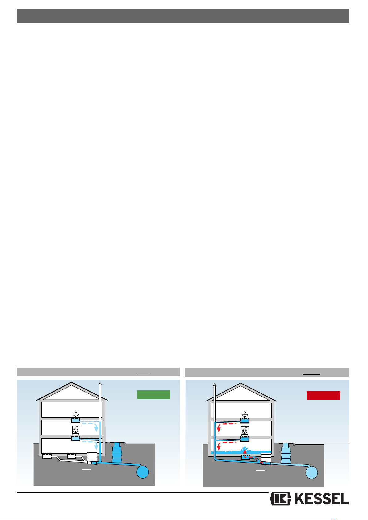
2.4 General instructions about the intallation of backwater valves
s
According to DIN EN 12056 backwater valves may not be used to protect all the draining points of a building - including those
above the backwater level (street level) - because if the backwater valve is closed, the
wastewater from above can no longer be
drained into the sewage pipe but will - according to the principle of communicating
pipes - escape from the drainage points furthest below the backwater level first (usually basement rooms) and thus flood the basement.
Only draining points below the backwater
level may be protected against backwater.
All draining points above the backwater
level must be discharged into the sewage
pipe with free gradient past the backwater
valve.
Consequence: separate pipe routing.
Domestic wastewater above the backwater
level can thus rise up to a maximum of street level inside the downpipe without flooding
the basement.
Rainwater must never be discharged via
backwater valves.
Installation of a backwater valve in the right place
Right!
Backwater protection
Backwater
level
Installation of a backwater valve in the wrong place
Wrong!
Backwater
level
Backwater protection
3
Page 4
3. Installation
Please note:
IN EN 12056 must always be heeded when
D
routing the base pipes. Downpipes must always be introduced downstream from the
Pumpfix® F (about 1m). In addition, a stilling
section must be observed upstream and downstream of the FKA (at least 1 m). During installation of the backwater valve, care must be
taken that there is a sufficient gap to the wall
for maintenance work to be carried out. The
KG pipe must not be connected directly to the
drain body but only to the muff.
Caution: During installation pay attention
to the direction of flow arrows on the product.
3.1 Kessel backwater pumping station
Pumpfix
ground plate
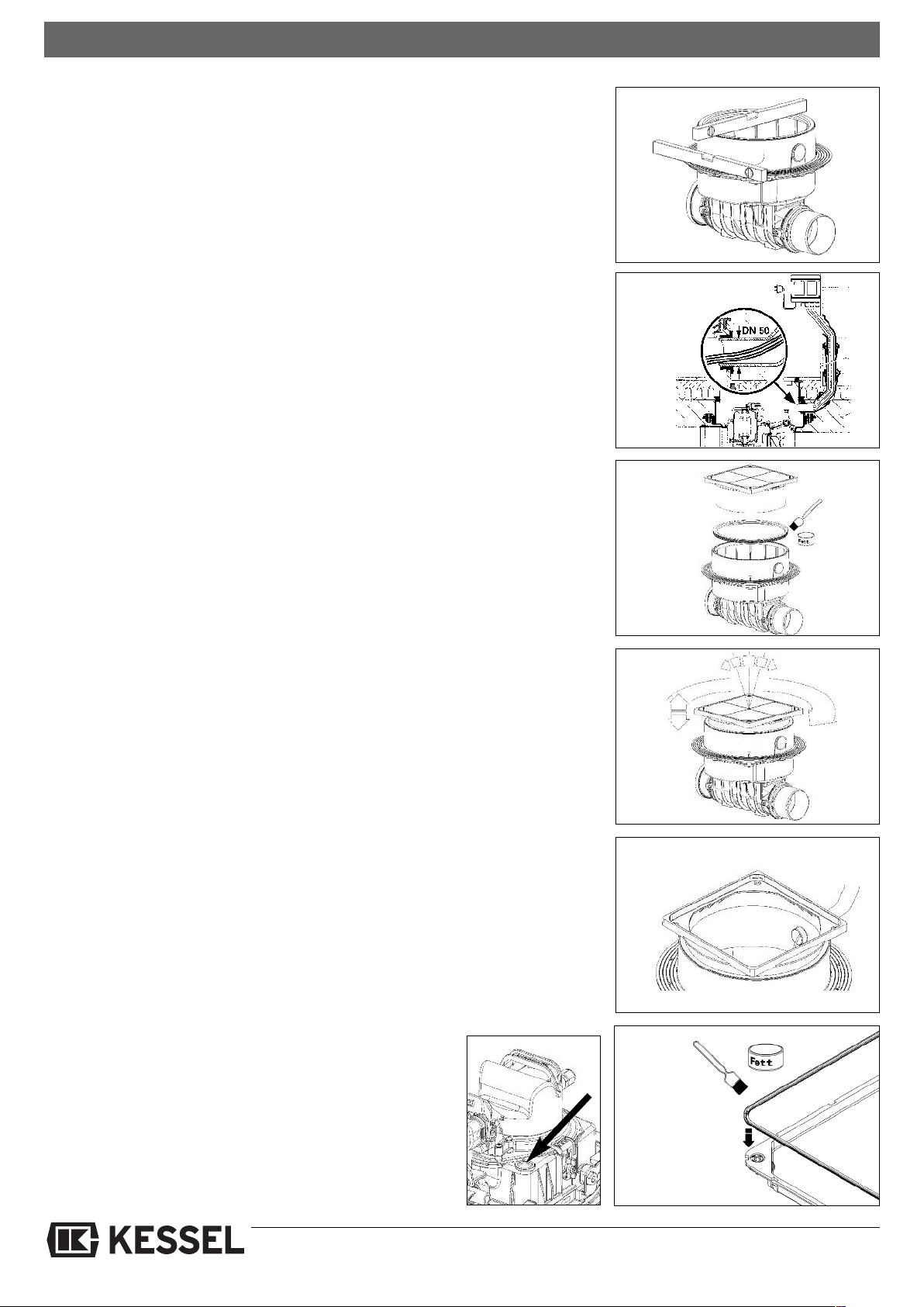
DThe drain body of the KESSEL-Pumpfix® F
must be aligned horizontally (see Fig. 1).
For connection of the electric cables of probe
and pump, a cable conduit (at least DN 50,
Kessel recommends 2 x 45° bends) must be
provided. A second probe cable and motor
connection cable must be connected for the
Komfort variant. For this, a cable conduit (at
least DN 70, Kessel recommends 2 x 45°
bends) must be planned. To do this, lay the
cable conduit to at least finished flooring height
(see Fig. 2) and insert in the cable duct in the
adapter of the KESSEL Pumpfix® F (cable
conduit should protrude about 2 cm into the interior - tightness (Fig. 5). Changes of direction
must be laid with bends of max. 45°. To guarantee proper aerating and venting of the pump
chamber, the cable conduit must not be sealed
airtight. Insert the enclosed profile lip seal into
the adapter groove and grease this. Then
mount the upper cover section (see Fig. 3).
Thanks to the telescopic design of the upper
cover section, the KESSEL-Pumpfix® F can be
adapted exactly to the prevailing installation
depth. Ground slopes of up to 5° can be compensated. The upper cover section can also be
turned to align the cover to the tile pattern, for
example (see Fig. 4). The seal must be
checked for a good fit after adjustment.
CAUTION:
The upper cover section must be shortened to the necessary size to achieve minimum installation depth. If necessary,
recesses must be cut out of the upper
cover section near the cable conduit and
the ventilation pipe. Maximum groundwater resistance is 2 m. Following final
alignment of the upper cover section, a
recess may have to be introduced near
the cable duct to enable the cable to be
pulled out again during later inspections
(see Fig. 5).
The lip seal must be fitted in the cover plate.
Care must be taken that the sealing lip and
®
F for installation in the
centring lug are facing upwards during installation. The centring lug must be placed in the
recess (see Fig. 6).
During installation, make sure that the function
of units in the chamber is not impaired by construction material.
Installation of covers with a choice of finishes (tile height max. 15 mm).
With the covers with a choice of finishes, tiles
or natural stone can be inserted in the cover on
site, so that they can be matched to the roomʼs
flooring. Products e.g. from PCI, Schomburg,
Deitermann are suitable for tile laying. To
achieve straightforward processing and adhesion, we recommend the following procedure:
Tile laying:
a) aPrime the cover plate e.g. with PCI primer
303. Following the respective flash-off time,
lay the tiles with silicone. This type of laying
is particularly suitable for thinner tiles since
the base can be filled up to the required
height.
b) Laying the tiles e.g. using PCI Silcoferm S
(self-adhesive silicone). This allows a thin
adhesive bed to be used, particularly good
for thicker tiles.
Laying natural stone:
(marble, granite, agglo-marble):
a) Prime the cover plate e.g. with PCI primer
303. Lay the natural stone panels using e.g.
PCI-Carralit..
b) Laying the natural stone panels using e.g.
PCI-Carraferm (special silicone for natural
stone). Areas of application analogue to
“Laying tiles”.
3.2 Recessed installation in the ground
plate
(order no. 83071). Chapter 3.4 must be heeded for installation in water load.
Depending on the installation depth, one or
max. two extension pieces can be used between the upper cover section and the adapter.
The respective seals must be greased accordingly.
Please note that with recessed installation you
still have to be able to reach down to the drain
body for maintenance purposes.
3.3. Ventilation connection
Pumpfix® F is fitted as standard with a ventilation valve with activated carbon filter. Alternatively, ventilation according to standard
can be connected. For
this, the ventilation
valve can be removed
and connected directly to a ventilation pipe
(to the roof).
ig. 1
F
fig. 2
Fig. 3
Fig. 4
fig. 5
Fig. 6
4
Page 5
3. Einbau
BWS
*
Fliesen
Estrich
Dämmung
Betonboden
S
4
5
2
1
BWS
Unterbeton
Fliesen
Estrich
Dämmung
Betonboden
Schutzbeton
Abdichtung
4
1
2
3
*
3.4 Installation in an exposed wastewaer pipe
t
The version for free-standing set-up is delivered with a protective hood to prevent damage to
the components following commissioning. Fig.
7 shows the cable ducts – 1 or 2 (depending on
the variant).
3.5 Installation in water load
(Seal set art. no. 83023
Fig. 7
If the valve is to be installed in water load,
the flange serves as the necessary sealing
level for a white or black tub (see Figure).
For this purpose, seal sheeting is clamped
between the plastic counterflange and the
compression seal flange integrated on the
drain body, and screwed together using the
enclosed screws.
The sheeting used on site can be used as
seal sheeting. For installation in a waterproof white tub, KESSEL also has matching
seal sheeting available made of natural rubber NK/SBR, where the bore holes for the
screws have already been cut out (see Fig.
8).
If it is necessary to perforate the waterproof
concrete tub to connect feed pipes, cable
conduits etc., these holes must also be set
up waterproof. Maximum groundwater resistance is 2 m.
nstallation with extension (order no.
I
83071).
Use of the extension allows the flange
height to be individually adjusted. The
ttachment must be shortened to the re-
a
quired height if necessary.
.6
3
Special features of Pumpfix®F
Comfort
Pumpfix F Komfort has an integrated drai-
ing function for surface water drainage.
n
3.7 Set-up
Connection of the draining function to the
feed cover is via the enclosed draining
connection. Insert the draining connection
into the prescribed opening and lock using
the one-handed quick-action closure.
Depending on installation depth (installation depth of the upper cover section), the
draining connection must be shortened to
the respective length (see Fig. 9) or extended using HT-pipe DN 70 if recessed installation using extension (art. no. 83071) is
used.
Fig 9
Seal seat (83023)
• Counterflange • Sealing sheet
Pressdichtungsflansch
Fig. 8
Pumpfix®F Comfort
Installation example “black tub”
Tiles
Screed
Insulation
Concrete floor
Protective concrete
Sealing
Underfloor
➀ KESSEL-Pumpfix® F, Staufix® FKA, Staufix® SWA, Controlfix
➁ Compression seal flange with seal set art. no. 83023
➂ Extension art. no. 83071
➃ Adapter DN 100 with compression seal flange made of stainless
steel art. no. 27198
Installation example “white tub”
➄ Elastomer sealing sheet art. no. 27159
➅ Upper cover section with plastic cover plate
➆ Control unit
➇ Locking lever
5
Tiles
Screed
Insulation
Concrete floor
WU-Beton
Page 6
4. Service and maintenance
.1 Service
4
The system must be checked once every
month by the operator through observation of the switching routine for operational
bility and leaks.
a
• Close emergency valve or with Komfort:
press test key to carry out functional test
on backwater valve -> valve closes
• Allow water to flow in
Wait until level-LED + pump trigger.
•
• Switch off water feed
• Switch off level-LED and wait for pump
• Open hand lever (vertical position OPEN)
-> Standard
Komfort: Please note that the backwater
valve must be open after the inspection
has been completed.
The pump should be checked at regular intervals. If operational noises increase,
pumping capacity decreases or there are
vibrations in the pipeline system, the pump
housing and impeller must be checked for
any stubborn soiling or wear.
4.2 Maintenance (at least every six
months)
CAUTION: Disconnect the unit from the
mains during all servicing work! Heed
safety instructions! No warranty will be
granted in the event of insufficient
maintenance! All the servicing and
maintenance work described below
may only be carried out by authorised
qualified personnel. Repairs may only
be carried out by the manufacturer.
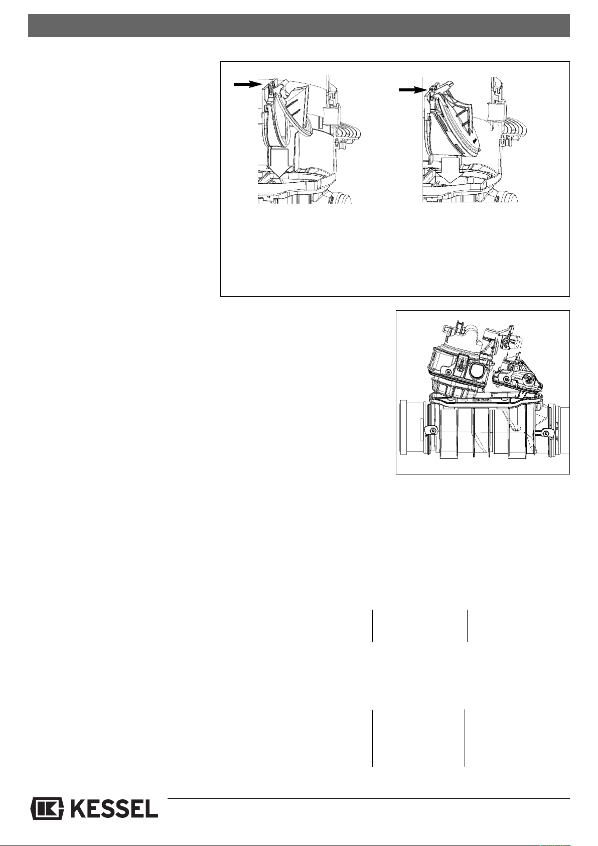
tandard Comfort
S
a) Pull the insertable part out
b) Clean all the parts
c) Check the seals
d) Apply lubricant (e.g. fittings grease)
to the outside of the seals of the insertable parts as well as the guide
parts of the flap valves
We recommend these jobs after longer periods of standstill or intermediate storage, too,
as well as after longer or frequent occurrences of backwater. If problems should occur
that cannot be eliminated, please contact
the specialist company who carried out the
installation (see stamp on cover sheet) if in
doubt.
4.2.1 Mounting the two covers (see Fig.
12, 13, 14)
Insert the covers on one side, push the other
side down and lock in place using the locking
levers. During installation of the overflow
cover the red flap lever or the motor flap position must always be “CLOSED”
e) Insert the insertable part exactly
f) Make sure the attachment clips are in
place properly!
g) Heed cover installation 4.2.1
h) Carry out functional test in accordan-
ce with instruction manual 010-846.
Abb. 12
DIN 1986, part 3, must be heeded during
maintenance work on systems. Maintenance work must be carried out at least every
six months by authorised qualified staff.
The following tasks have to be carried out:
• Visual inspection of the complete system
• Thorough cleaning of the complete system and the pump
• Check on the complete system and pump
housing for external damage and visible
wear
• Check on the pump for free movement,
wear and deposits
• Check the connection cables for mechanical damage and wear
• Check the seal connections for leaks and
any recognisable wear
• Insulation test on the pump motor
• Check the control unit for damage and
soiling
• Check and clean the ventilation valve
• Clean the optical probe
4.3 Test
4.3.1 Test Standard
1. Hold the pump probe into the water "On" level Level-LED lit
Pump starts Pump-LED lit
4.3.2 Test Comfort
1. Hold the motor probe into the water Flap closes Backwater-LED flashes
Flap-LED flashes
Flap closed Backwater-LED flashes
Flap-LED lit
2. Hold the pump probe into the water Pump starts Pump-LED lit
6
Page 7
4. Service and maintenance
4.4 Pump removal:
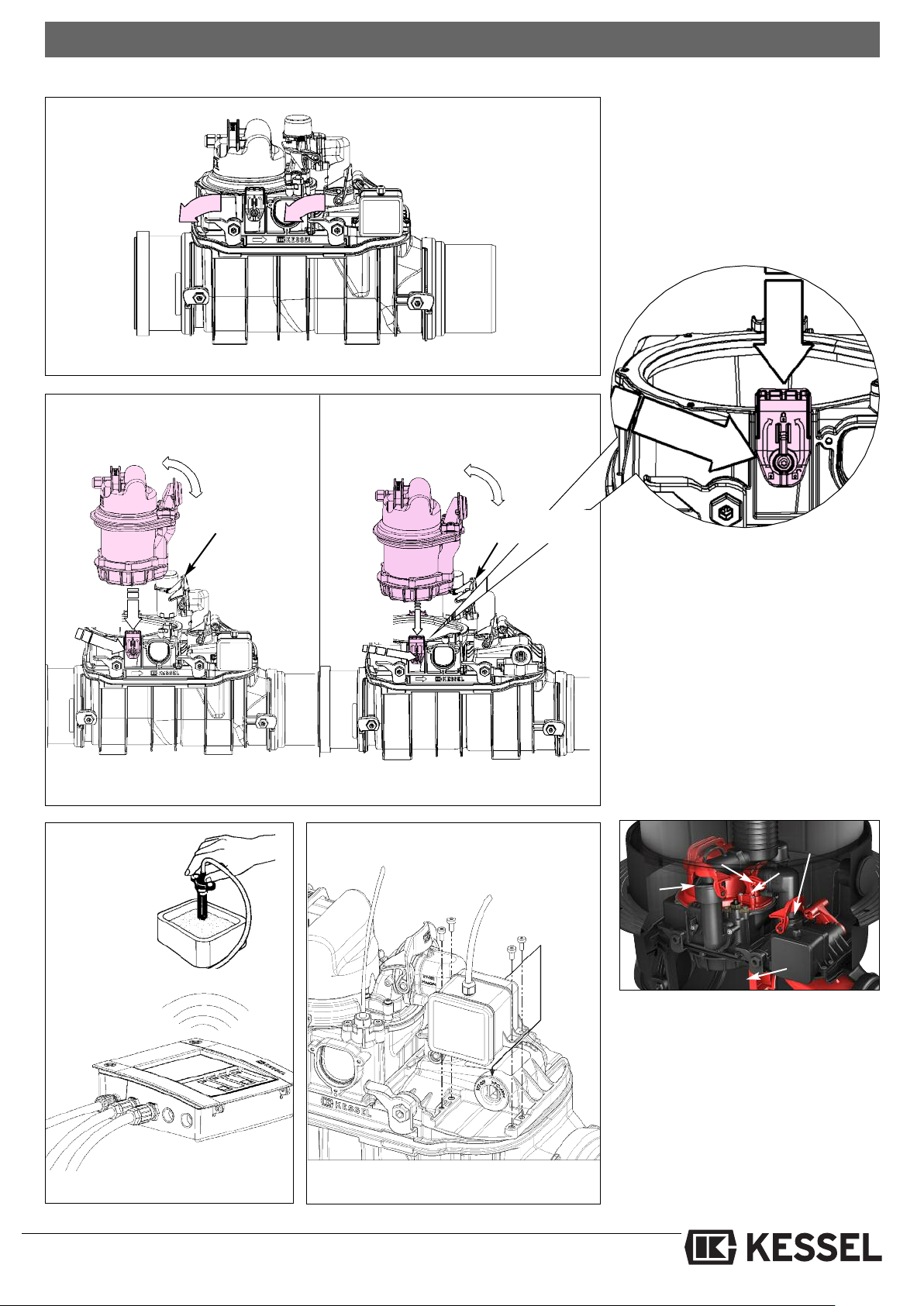
T
To do this, turn both pump removal levers
hrough 180°. This makes them fold out-
t
wards to the side so that the pump can be
lifted out.
he pump can be removed individually.
Fig. 13 shows the Comfort variant
Locking lever
muff
Pump removal lever
Fig. 14
Pump removal lever
Lock both sides!
Locking lever
muff
4.5 Motor installation:
The levelled drive shaft of the motor must
be in a vertical position (state on delivery). Move the locking lever of the operating valve on the locking cover to the
“CLOSED” position, insert the drive
motor into the drive groove from above,
and screw in place using the four M5 x 12
screws (TX25) on the locking cover (Fig.
16).
4.6 Removing motor ground installation
Fig. 15 Probe test
Fig. 16 Motor installation
7
In this case, the outlet cover must be dismantled to remove the motor. To do this,
open the locking lever and take the out-
let muff out. Loosen levers ②and ③and
remove the bypass muff, to do this tilt
pump connection muff ④away or remo-
ve the pump if necessary.After removing
the two cover locking levers ⑤the outlet
cover can be removed. Now the motor
can be screwed off.
Page 8
4. Service and maintenance
4.7 How the emergency valve works
4.7.1 Standard
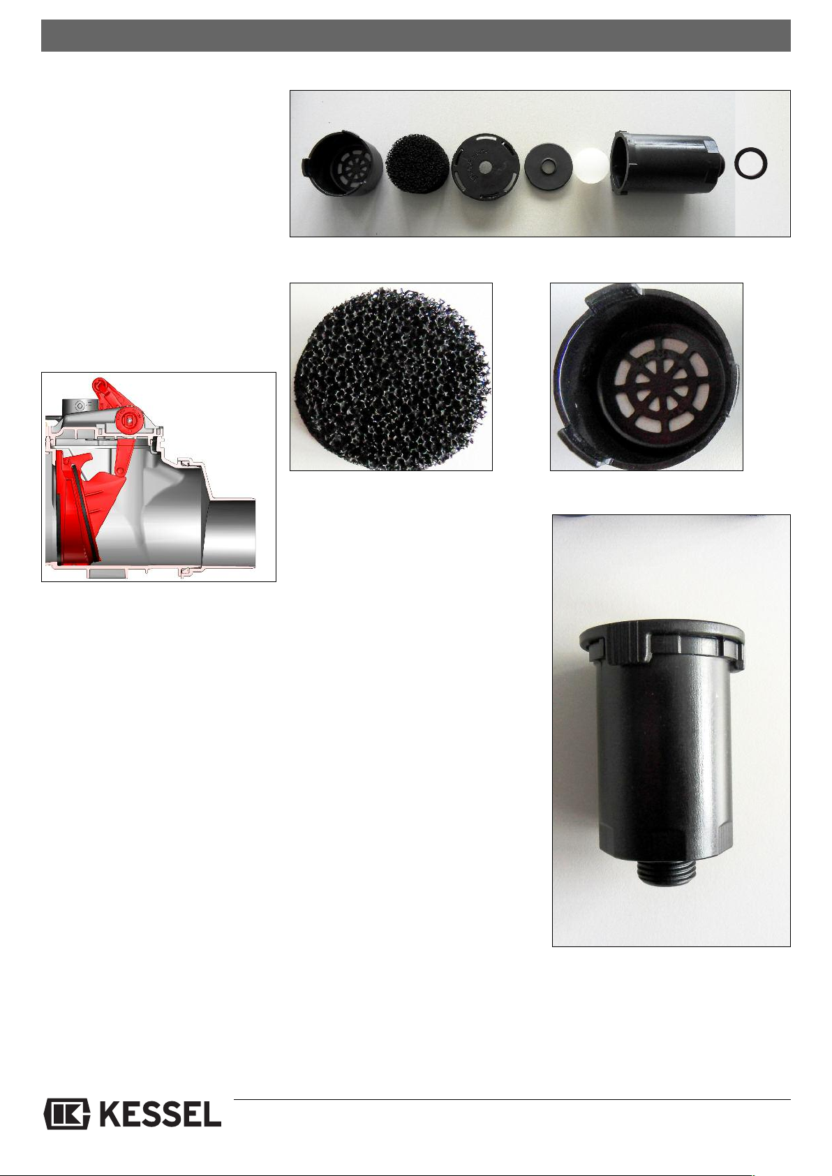
Locking position (Fig. 17, emergency
alve completely closed): The hand lever
v
of the emergency valve must be put in the
respective CLOSED position. The backwater flap works as a pipe barrier. This
function is only considered as protection
rom backwater during longer periods of
f
absence (e.g. holidays).
Connected draining points are still drained. The emergency valve must be released again for normal operation.
Abb. 17
Fig. 17 Bleeder
Emergency flap can be locked by hand
4.7.2 Komfort
Locking position: The backwater flap is
closed by pressing the TEST key (flap).
The backwater flap works as a pipe barrier. This function is only considered as
protection from backwater during longer
periods of absence (e.g. holidays).
Connected draining points are still drained.
After return, the emergency valve
must be released again for normal
operation: by pressing the TEST key
(flap) again.
Make sure that there is no backwater
when this takes place.
Fig. 18 Activated carbon filter
The bleeder(Fig. 17 from right to left) comprises seal, drain body, float ball, seal,
bayonet locking cap, activated carbon filter and cover.
Pull the cover off (Fig. 19) by tilting it slightly to the side. Then turn bayonet locking
cap (Fig. 20) ➀ and pull it up and off ②.
Removesealand floatballand clean everything. Re-assembly takes place in reverse order.
Fig. 19 Cover
4.8 Servicing the ventilation
The ventilation (see spare parts section 6)
must be cleaned regularly and the activated carbonfilter (Fig. 18) must be changed
annually or as required.
The ventilation must be cleaned and
checked after every pump failure.
Fig. 20 Bayonet locking cap
8
Page 9
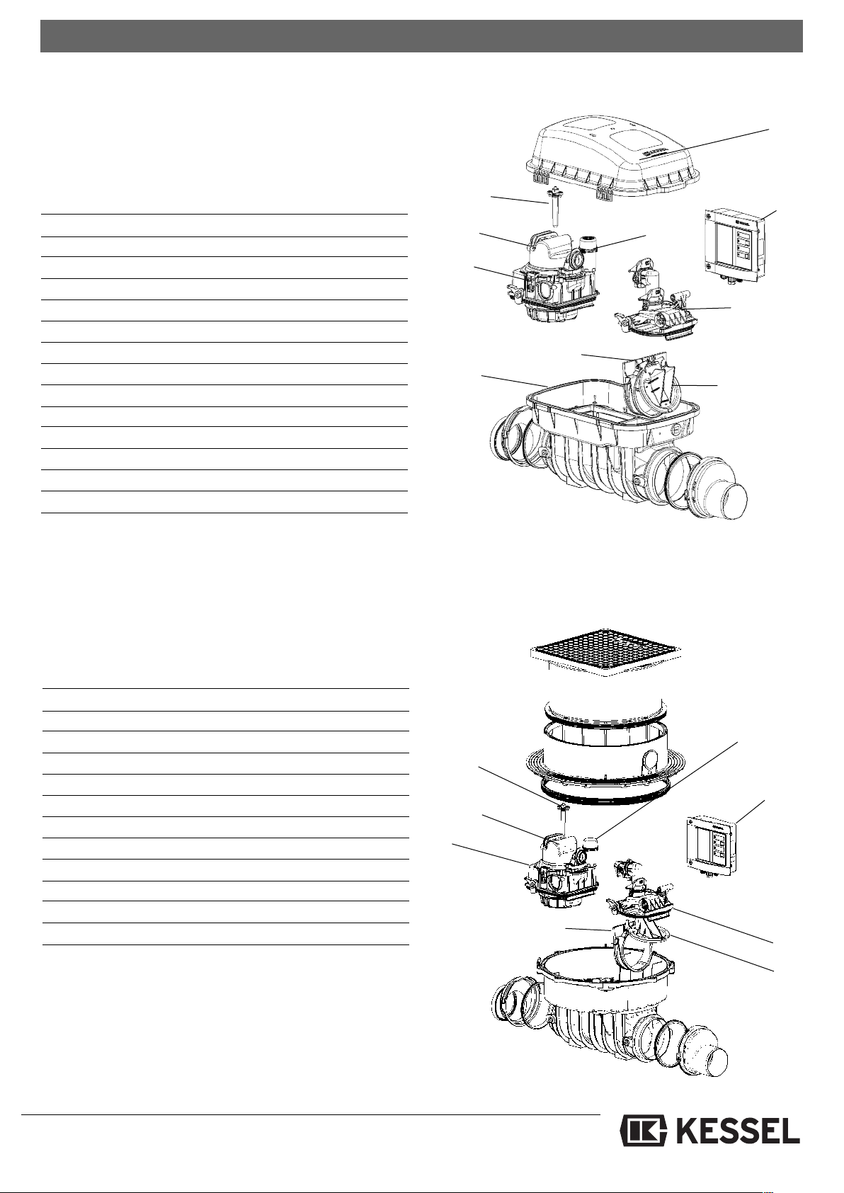
5. Spare parts
5.1 Standard
®
umpfix
P
All spare parts can be purchased from a specialist company.
F
for installation in an exposed wastewater pipe
햺
esignation Art. no.
D
Pumpfix®F
) Additional board for potential-free contact 80072
a
) Remove signal generator 20 m 20162
b
c) Battery 9V (2 units required) 197-081
Optical probe IP 68 (5 m, inc. adapters) 80888
Cover pump feed side (without outlet function) 28052
Pumpfix®F
Pumpfix®F
Ventilation complete 28060
a) Activated carbon filter 28061
Mechanical flap 80033
Insertion part for mechanical flap 80034
Hood 80031
햻
Transition piece 83032
Seal set II 70319
Pumpfix®F
control unit Standard IP 54 28073
-
-cover Standard outlet side 28053
-pump IP 68 (5m, inc. plug) 28351
for installation in the ground plate
햴
햻
햶
햳
햹
햷
a
햵
a,b,c
All spare parts can be purchased from a specialist company.
Designation Art. no.
Pumpfix®F
a) Additional board for potential-free contact 80072
b) Remove signal generator 20 m 20162
c) Battery 9V (2 units required) 197-081
Optical probe IP 68 (5 m, inc. adapters) 80888
Cover pump feed side (without outlet function) 28052
Pumpfix®F
Pumpfix®F
Ventilation complete 28060
6a) Activated carbon filter 28061
Mechanical flap 80033
Insertion part for mechanical flap 80034
Seal set II 70319
-control unit Standard IP 54 28073
-cover Standard outlet side 28053
-pump IP 68 (5m, inc. plug) 28351
햹
햷
a
a,b,c
햵
햸
9
Page 10
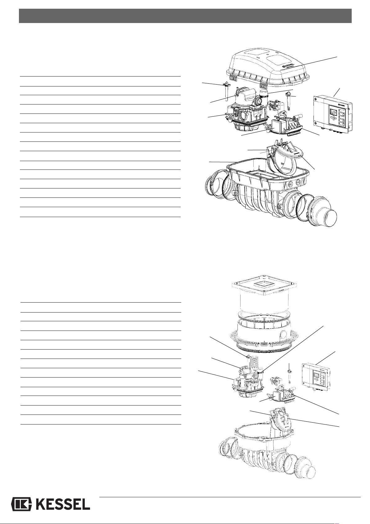
5.2 Comfort
5. Spare parts
Pumpfix®F
All spare parts can be purchased from a specialist company.
Designation Art. no.
Pumpfix®F
a) Additional board for potential-free contact 80072
b) Remove signal generator 20 m 20162
c) Battery 9V (2 units required) 197-081
Optical probe IP 68 (5 m, inc. adapters) 80888
Cover pump feed side (without outlet function) 28052
Pumpfix®F
Pumpfix®F
Ventilation complete 28060
a) Activated carbon filter 28061
Motor-driven flap 80038
Insertion part for motor-driven flap 80039
Hood 83031
햻
Transition piece 83032
햽
Drive motor IP 68 (5m cable) 80076
Seal set II 70319
for installation in an exposed wastewater pipe
-control unit Komfort IP 54 28071
-cover Komfort outlet side 28056
-pump IP 68 (5m, inc. plug) 28351
햳
햴
햻
햶
햽
햹
햷
햳
햺
a
햵
a
,b,c
Pumpfix®F
All spare parts can be purchased from a specialist company.
Designation Art. no.
Pumpfix®F
a) Additional board for potential-free contact 80072
b) Remove signal generator 20 m 20162
c) Battery 9V (2 units required) 197-081
Optical probe IP 68 (5 m, inc. adapters) 80888
Cover pump feed side (with outlet function) 28054
Pumpfix®F
Pumpfix®F
Ventilation complete 28060
6a) Activated carbon filter 28061
Motor-driven flap 80038
Insertion part for motor-driven flap 80039
햺
Drive motor IP 68 (5m cable) 80076
Seal set II 70319
for installation in the ground plate
-control unit Komfort IP 54 28071
-cover Komfort outlet side 28056
-pump IP 68 (5m, inc. plug) 28351
햹
햺
햷
a
a,b,c
햵
햸
10
Page 11

6. Warranty
1. In the case that a KESSEL product is defective, KESSEL has the option of repairing or replacing the product. If the product remains defective after the second
attempt to repair or replace the product or
it is economically unfeasible to repair or
replace the product, the customer has
he right to cancel the order / contract or
t
reduce payment accordingly. KESSEL
must be notified immediately in writing of
defects in a product. In the case that the
defect is not visible or difficult to detect,
KESSEL must be notified immediately in
writing of the defect as soon as it is discovered. If the product is repaired or re-
laced, the newly repaired or replaced
p
product shall receive a new warranty
identical to that which the original (defective) product was granted. The term defective product refers only to the product
or part needing repair or replacement
and not necessarily to the entire product
or unit. KESSEL products are warranted
for a period of 24 month. This warranty
period begins on the day the product is
shipped form KESSEL to its customer.
The warranty only applies to newly ma-
ufactured products. Additional informa-
n
tion can be found in section 377 of the
HGB.
In addition to the standard warranty,
KESSEL offers an additional 20 year warranty on the polymer bodies of class I / II
fuel separators, grease separators, inspection chambers, wastewater treat-
ent systems and rainwater storage
m
tanks. This additional warranty applies to
the watertightness, usability and structural soundness of the product.
A requirement of this additional warranty
is that the product is properly installed
and operated in accordance with the valid
installation and user's manual as well as
the corresponding norms / regulations.
2. Wear and tear on a product will not be
onsidered a defect. Problems with pro-
c
ducts resulting from improper installation,
handling or maintenance will also be considered a defect.
Note: Only the manufacturer may open
sealed components or screw connections. Otherwise, the warranty may beco-
e null and void
m
01.06.2010
11
Page 12
7. Commissioning Protocol for installer
Separator Type: __________________________________________________________
Day / Hour __________________________________________________________
roject description /Building services supervisor __________________________________________________________
P
Address __________________________________________________________
Telephone / Fax __________________________________________________________
Builder __________________________________________________________
Address __________________________________________________________
Telephone / Fax __________________________________________________________
Planner __________________________________________________________
Address __________________________________________________________
Telephone / Fax __________________________________________________________
Contracted plumbing company __________________________________________________________
Address __________________________________________________________
Telephone / Fax __________________________________________________________
KESSEL-Commissions no.:
System operator /owner __________________________________________________________
Address __________________________________________________________
Telephone / Fax __________________________________________________________
User __________________________________________________________
Address __________________________________________________________
Telephone / Fax __________________________________________________________
Person of delivery __________________________________________________________
Other remarks __________________________________________________________
The system operator, and those responsible, were present during the commissioning of this system.
____________________________ ____________________________ ____________________________
Place and date Signature owner Signature user
12
Page 13

Notice
13
Page 14
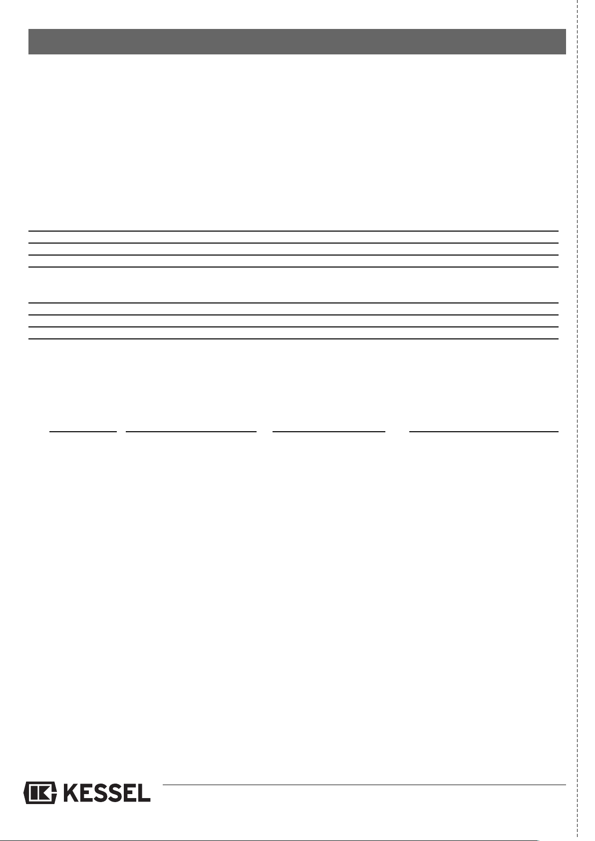
8. Commissioning Protocol for installation company
Handover certificate (copy for the company carrying out the installation)
The initial operation and instruction was carried out in the presence of the person authorised to perform the ac-
eptance and the system operator.
c
The system operator/person authorised to perform the acceptance was informed about the obligation to service
the product according to the enclosed operating instructions.
I
The client/ person responsible for initial operation was handed the following components and/or product components
Initial operation and instruction is being carried out by (company, address, contact, phone)
The exact coordination of the dates for initial operation/instruction is being carried out by the system operator and person
responsible for initial operation.
Place, date Signature of person Signature of system operator Signature of the company
nitial operation and instruction were not carried out.
authorised to perform acceptance carrying out the installation work
14
Page 15

15
Page 16
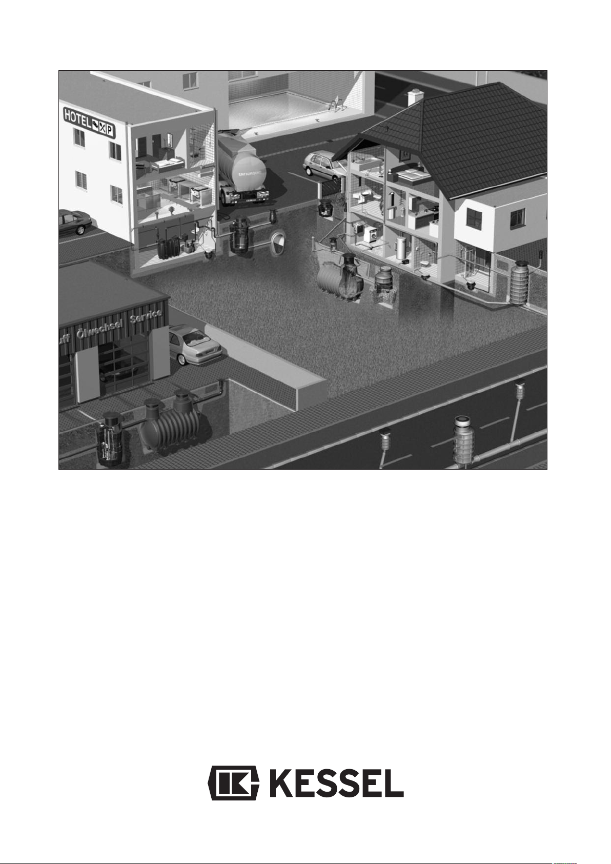
K
Backwater protection
K
Lifting Stations and pumps
K
Drains and shower channels
K
Separators
-Grease Separators
-Oil-/Fuel-/Coalescence
Separators
-Starch Separators
-Sediment Separators
K
Septic Systems
K
Inspection Chambers
K
Rainwater Management
Systems
 Loading...