

Kessel Aqualift F Standard, Aqualift F Duo Standard Installation, Operating And Maintenance Instructions
Page 1
INSTALLATION, OPERATING AND MAINTENANCE INSTRUCTIONS
m
i
t
Si
ch
e
rh
e
i
t
ge
pr
üft
e
Qua
l
i
t
ä
t
BauartBauart
geprüftgeprüft
u
nd überwachtund überwacht
Bauart
geprüft
u
nd überwacht
L
GA
Landesgewerbeamt Bayern
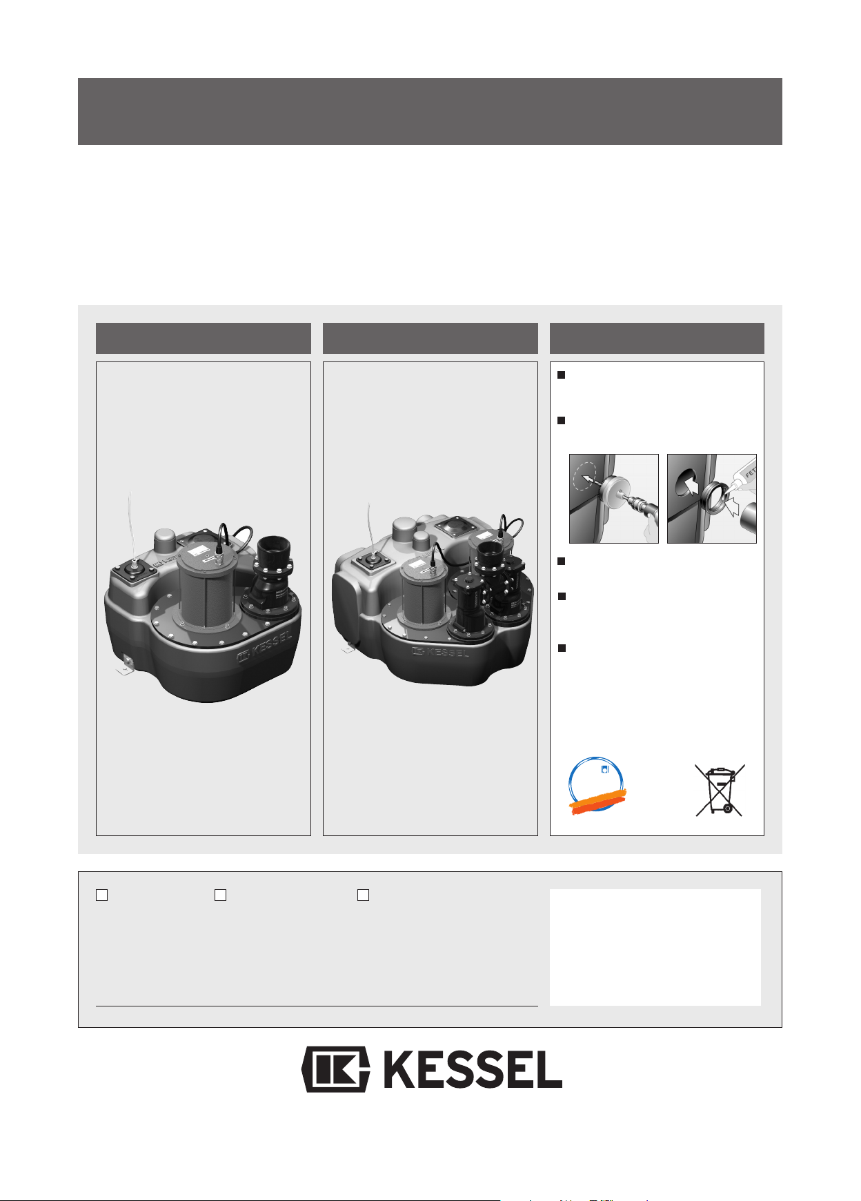
KESSEL-lifting station Aqualift쏐F (400V) Standard
for wastewater with and without faeces for
free-standing installation in rooms protected from frost
Aqualift쏐F
Aqualift쏐F Duo
Product advantages
Simple connection through
moulded connecting pieces
Drilling surfaces for further
connections
Fully automatic operation
Maintenance-friendly
PE-tank
General technical approval
no. Z-53.2-424
Installation
Commissioning Instruction
The installation and service of this unit should be carried out by
a licensed professional servicer
Name/Unterschrift Datum Ort
Edition 07/2010
Stempel Fachbetrieb
Subject to technical amendment
ID-Nr. 206-818EN
Page 2
1. Safety information
eneral safety precautions
G
uring installation, operation, maintenance or repairs to the system, please observe the accident pre-
D
vention regulations, the applicable DIN and VDE standards and guidelines, and also the regulations of
the local energy and supply companies.
he systems may not be operated in explosive areas
T
lectrical hazards
E
This system contains electrical voltages and controls rotating mechanical parts. Non-observation of the
operating instructions could lead to serious damage, injury or even fatal accidents.
The system must be securely disconnected from the mains supply before commencing any work on it.
The local master switch and the cut-outs must be turned off, i.e. switch the system to zero-potential and
take precautions to ensure it cannot be switched on again. If only cut-outs are available, these must be
switched off and a sign attached to prevent third parties from switching the main fuse on again.
VDE 0100 applies to all electrical work on the system.
The switchgear and the level control are under voltage and may not be opened. Only electricians may
work on the electrical equipment. The term 'electrician' is defined in the VDE 0105.
Steps must be taken to ensure that the electrical cables and all other electrical system parts are in a
fully functional condition. If any parts are damaged, the system may not be operated and/or must be immediately shut down.
Risk of burning fingers and hands
The driving engine may become very hot during operation
Risk of injury to fingers and hands
The pumps are equipped with a closed impeller. Therefore work on the pump may only be carried out if
the power supply has been disconnected and the rotating parts have stopped rotating.
Take care on sharp edges during maintenance or repair work.
Risk due to heavy weights
The lifting system models with one pump weigh around 45 kg, and with two pumps around 84 kg. The
systems may only be lifted or mounted by two persons with appropriate care wearing protective equipment (e.g. protective shoes).
The pumps may only be removed slowly or placed in the pump flange opening by two persons (if suitable precautions to prevent slipping have been taken).
2
Page 3
1. Safety information
ealth risk
H
he wastewater system transports wastewater that contains faeces; in turn this faeces may contain
T
harmful substances. Whenever working on the system, always ensure that there is no direct contact
between the wastewater and/or soiled system parts and your eyes, mouth or skin. In the event of direct
contact, clean the affected part of your body thoroughly and disinfect if necessary. It is also possible that
he atmosphere in the tank may be harmful.
t
Therefore before opening the cleaning aperture (or removing the pump) ensure that the respective room
s adequately ventilated or provide for (forced) ventilation during the opening process.
i
Noise pollution
When the pump is operated, a noise level is created that may be a nuisance depending on how the pump
is installed. If there are maximum noise level stipulations that need to be observed, appropriate measures need to be taken. The sound damping set from KESSEL may also be helpful here.
Risk of explosion
The inside of the tank is considered to be explosive within the meaning of EN 12050 because the biological digestive process may create flammable gases (hydrogen sulphide, methane gas). Therefore,
when unscrewing the pump or the cleaning aperture lid or any other parts, ensure that the room is adequately ventilated or provide for (forced) ventilation during the opening process. Whilst the tank is open,
it is forbidden to smoke or carry out any other activities in the respective room that could cause the gas
to ignite (e.g. operation of electrical devices without encapsulated motors, metalworking etc.).
3
Page 4
Table of contents
1. Safety information
2. General
3. Technical data
. Installation and assembly
4
5. Electrical connections
6. Initial operation
...........................................................................................................Page 2
2.1 Area of application...............................................................Page 5
2.2 System description ..............................................................Page 5
3.1 Dimensions..........................................................................Page 6
3.2 Pumps .................................................................................Page 7
3.3 Electric switch unit...............................................................Page 8
.1 Fitting the collecting tank.....................................................Page 9
4
4.2 Connecting the pipes...........................................................Page 9
4.3 Setting the pressure level switches .....................................Page 11
5.1 General notes......................................................................Page 12
5.2 Installation of the switch unit................................................Page 12
5.3 Installation, wiring................................................................Page 13
5.4 Checks ................................................................................Page 16
5.5 Configuration of switch unit .................................................Page 17
6.1 General notes......................................................................Page 18
6.2 Pressure outlet connecting pieces.......................................Page 18
6.3 Operating the switch unit.....................................................Page 18
7. Inspection and maintenance
8. Malfunctions and
troubleshooting
9. Control unit
10. Spare parts and accessories
11. Warranty
6.4 Functional description..........................................................Page 19
6.5 Functional test .....................................................................Page 19
7.1 Notes on the pump ..............................................................Page 20
7.2 Notes on aeration device.....................................................Page 20
7.3 Notes on the electrical switch unit .......................................Page 21
8.1 General malfunctions ..........................................................Page 22
8.2 Malfunction messages.........................................................Page 24
8.2.1 Irregular level states ............................................................Page 26
8.2.2 Internal monitoring...............................................................Page 27
8.2.3 "Malfunction" message... .....................................................Page 27
8.2.4 "Alarm" message .................................................................Page 27
8.2.5 What to do when...…...........................................................Page 27
9.1 Switch unit (from model year 01/10) ....................................Page 28
9.2 Switch unit (up to model year 12/09) ...................................Page 29
10.1 Accessory parts...................................................................Page 34
10.2 Spare parts..........................................................................Page 35
...........................................................................................................Page 40
12. Declaration of conformity
13. Handover certificate
...........................................................................................................Page 41
...........................................................................................................Page 42
4
Page 5
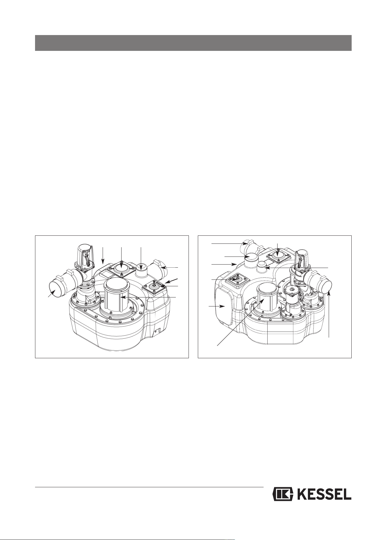
.1 Area of application
2
2. General
he lifting stations pump wastewater with and without se-
T
wage that occurs below the sewer and backwater level fully
automatically into the sewage system in accordance with the
requirements of DIN 1986. They are only suitable for use for
omestic wastewater, for example in single family and multi-
d
family homes, business, hotels and restaurants, department
tores, hospitals, schools or similar cases.
s
If the feed to the lifting stations must not be interrupted during normal operation, the lifting station must be equipped
with a second pumping device of the same capacity which
switches on immediately when required (twin station instead
of single station).
2.2 System description
The KESSEL pumping station
system basically comprises the following assemblies:
Aqualift®F
1.8 1.3 1.5
as a single or twin
1.4
®
he KESSEL lifting station Aqualift
T
for free-standing set-up in frost-protected rooms. The respective switch unit must be installed in a flood-proof, dry and
frost-protected room. The wastewater submersible pumps
re equipped with a single-channel impeller and have a com-
a
pletely free passage of 40 mm. The pressure pipes must be
t least of the size DN 80, the ventilation pipes at least DN
a
70. Wearing media must be kept away from the pump impeller.
The systems are suitable for constant wastewater temperatures up to 35°C. A maximum temperature of 60°C is permissible briefly (up to 10 minutes).
1.4
1.9
1.6
1.3
has been designed
F
1.5
1.6
1.2
1.7
1. Collecting tank made of PEHD
gas and watertight, with
1.1 One or two wastewater pumps, each of which has
a 5 m connection cable
1.2 Pneumatic level control with 5 m air hose each
1.3 Cleaning opening
1.4 Connection for DN 100 inlet pipe
1.5 Connection for ventilation pipe
1.6 Connection for manual diaphragm pump
1.7 DN 100 pressure outlet connecting pieces with
integrated backwater flap and aerating device
1.8 Pre-scored areas
1.1
1.2
1.8
1.7
1.1
2. Electric switch unit
(see illustrations in chapter 8)
3. Accessory parts (not illustrated)
3.1 Brackets with screws and dowels for fixing the tank to
the floor
3.2 Rubber hose with hose clamps for the pressure pipe
connection
3.3 Sound-insulating underlay mat
Mono: Art. no. 28692
Duo: Art. no. 28693
A detailed description of the system set-up can be found in
chapter 10, Spare parts.
)
5
Page 6
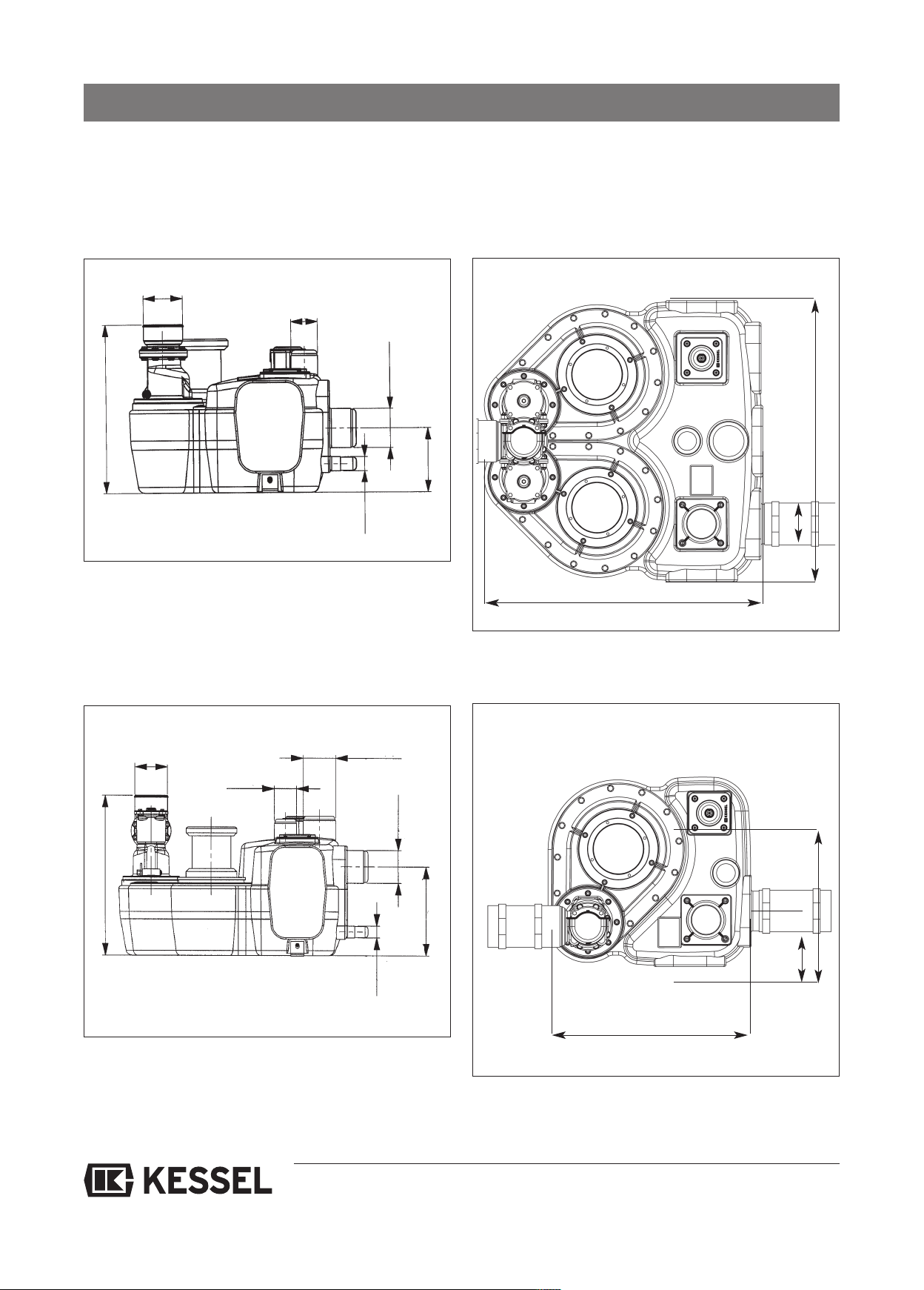
3. Technical data
3.1 Dimensions
3.1.1 Single system 1.1 kW with pressure outlet DN 100, order no. 28645 / 28644 (with non-return valve)
ingle system 2.2 kW with pressure outlet DN 100, order no. 28647 / 28649 (with non-return valve)
S
DN100
Ø110
DN70
Ø75
Ø110
DN100
475
180
Zulaufhöhe
Ø40
DN32
773
3.1.2 Twin system 1.1 kW with pressure outlet DN 100, order no. 28652 / 28659 (with non-return valve)
Twin system 2.2 kW with pressure outlet DN 100, order no. 28634 / 28631 (with non-return valve)
DN100
Ø110
DN70
Ø75
DN100
Ø110
Ø110
DN100
780
160
539
300
Zulaufhöhe
Ø40
DN32
564
525
154
6
Page 7
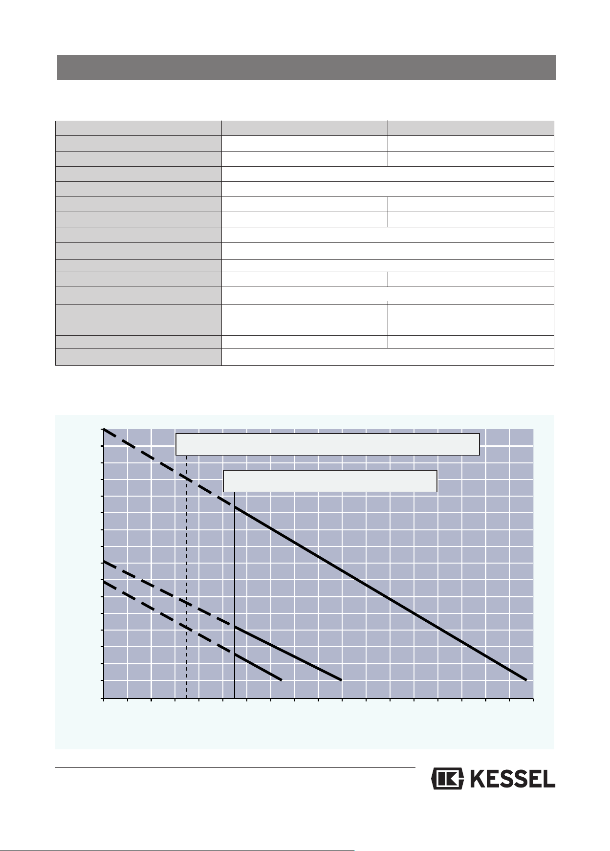
3. Technical data
2
0
10
1
4
3
6
5
8
7
9
11
12
13
14
15
0
8412162024283236404446485052545658
3.2 Pumps (Aqualift F Mono, Duo)
Type 400 V - 1,1 kW 400 V - 2,2 kW
ominal capacity (P2) 1,15 kW 2,4 kW
N
Rated capacity (P1) 1,6 kW 3,1 kW
Operating voltage 400 V DS
Rated frequency 50 Hz
Nominal current 3,2 A 5,4 A
Start-up current 14,4 A 30,8 A
Fuse 3 x 16 A slow-blow
Connection cable 5 m long, 7 x 1,5 mm
Temperature of material pumped 35 °C
Weight (pump) 30 kg 31 kg
Protective rating IP 68 ( 24h; 3m WS)
Operating mode
Max. period of perm. operation 240 Min. 30% duty cycler
Sound level < 70 db < 70 db
Pump volume 20 l (Mono), 50 l (Duo)
S1 S3
2
Pumping capacity diagram
Pumping height m
Q min nach DIN 1986 (vmin = 0,7m/s) für DN 80
Q min nach DIN 1986 für DN 100
400 V
230 V
1,1 kW
1,1 kW
400 V
2,2 kW
Pumping capacity Q (m3/ h)
7
Page 8

3. Technical data
3.3 Electric switch unit
3.3.1 General technical data
Ambient conditions
Permissible temperature range: 0 to 50 °C
ermissible air humidity: 10 to 80 %
P
non-condensing
Maximum operating height: 2000 m above sea level
Power consumption
max. ca. 11 VA for single, 15 VA for double system
(electronics without motor)
Protective class
Class 1 with function grounding of the secondary electronics
circuit (PELV)
Protective rating
IP 54 when fitted correctly
3.3.2 Supply
Mains supply
PE/N/L1/L2/L3 according to marking on terminal block for
single / twin system
Operating voltage
400 / 230 V 3~ 50 Hz ± 10% rotary current (L1=230V AC /
50Hz±10% for supplying the power packs for the electronics)
3.4 Outputs
3
.
Malfunction" relay
"
Changeover contact; opening contact, centre contact,
closing contact each max. 2A
Warning" relay
"
Changeover contact; opening contact, centre contact,
closing contact each max. 2A
Mains
2 x N, max. each 2A
2 x L, max. each 2A
for supplying malfunction/alarm warning devices, switched
through the "malfunction"/"warning" relays, without internal
fusing
Motor (single system)
Motor PE Mains connection
(grey double-deck terminals up to model year 01/10)
(spring terminal on board from model year 01/10)
Motor U T1 contactor
Motor V T2 contactor
Motor W T3 contactor
max. 4kW
}
Pre-fuse required
max. 16 A / phase (to be provided on installation side)
3.3.3 Inputs
a) From model year 01/10
Level inputs each approx. 24 V output; approx. 5 mA input
Each pump has the circuit TF1 and TF2
b) Up to model year 01/10
Level inputs each 15.8 V input approx. 5 mA circuit TF (or TF1
and TF2) and E7 (or E7 and E8) for connecting the temperature switch of the pump motor, sensor supply input max. 18 mA
for TF and 9 mA for E7
Motor 1/2 (twin system)
Motor 1/2 PE mains connection
(4-fold mains through terminals up to model year 01/10)
(spring terminal on board from model year 01/10)
Motor 1/2 U T1 contactor 1/2
Motor 1/2 V T2 contactor 1/2
Motor 1/2 W T3 contactor 1/2
max. 4kW
}
8
Page 9
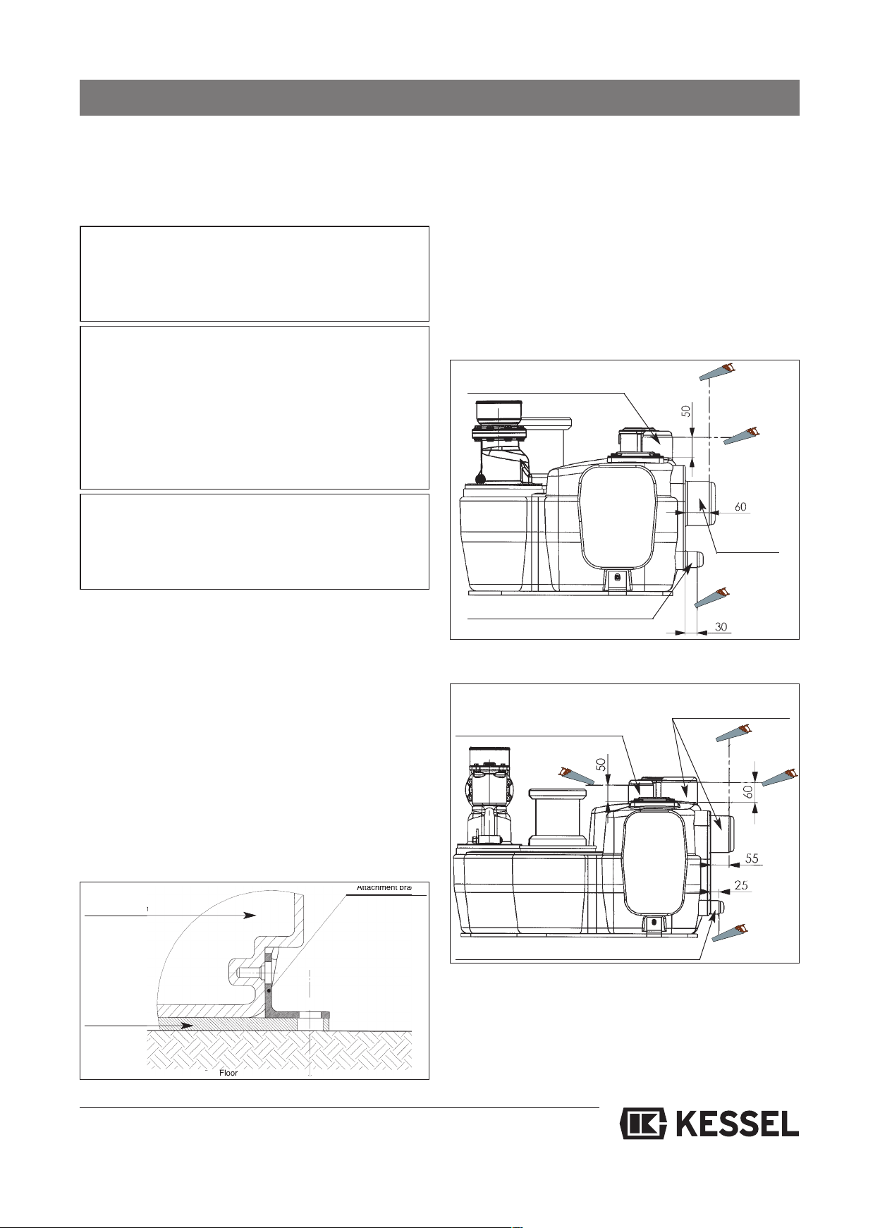
4. Installation and assembly
he following parts are included in the scope of supply (see
T
section 2.2):
Collecting tank with all components mounted
-
- Electric switch unit
- Accessory parts
MPORTANT:
I
The electric switch unit must be stored frost-free and dry.
If the system is not connected directly to the power supply on installation, the switch unit inc. all electric parts
ust be stored accordingly.
m
CAUTION:
Hazard through heavy weights. The lifting stations weigh approx. 45 kg (single system) and approx 84 kg (twin system).
The parts may only be lifted and/or assembled using suitable equipment and exercising appropriate caution. If the systems are dropped, this can lead to irreparable damage to
system parts (e.g. pump) or the whole system. Such damage is not covered by the warranty.
INSTALLATION SITE:
The KESSEL lifting station Aqualift®F has been designed
for free-standing set-up in frost-protected rooms. The respective switch unit must be installed in a flood-proof, dry
and frost-protected room.
.2 Connecting the pipes
4
ll pipes must be routed so that they can run empty auto-
A
matically. All pipe connections must be flexible and sound insulated.
here are two types of connection possible:
T
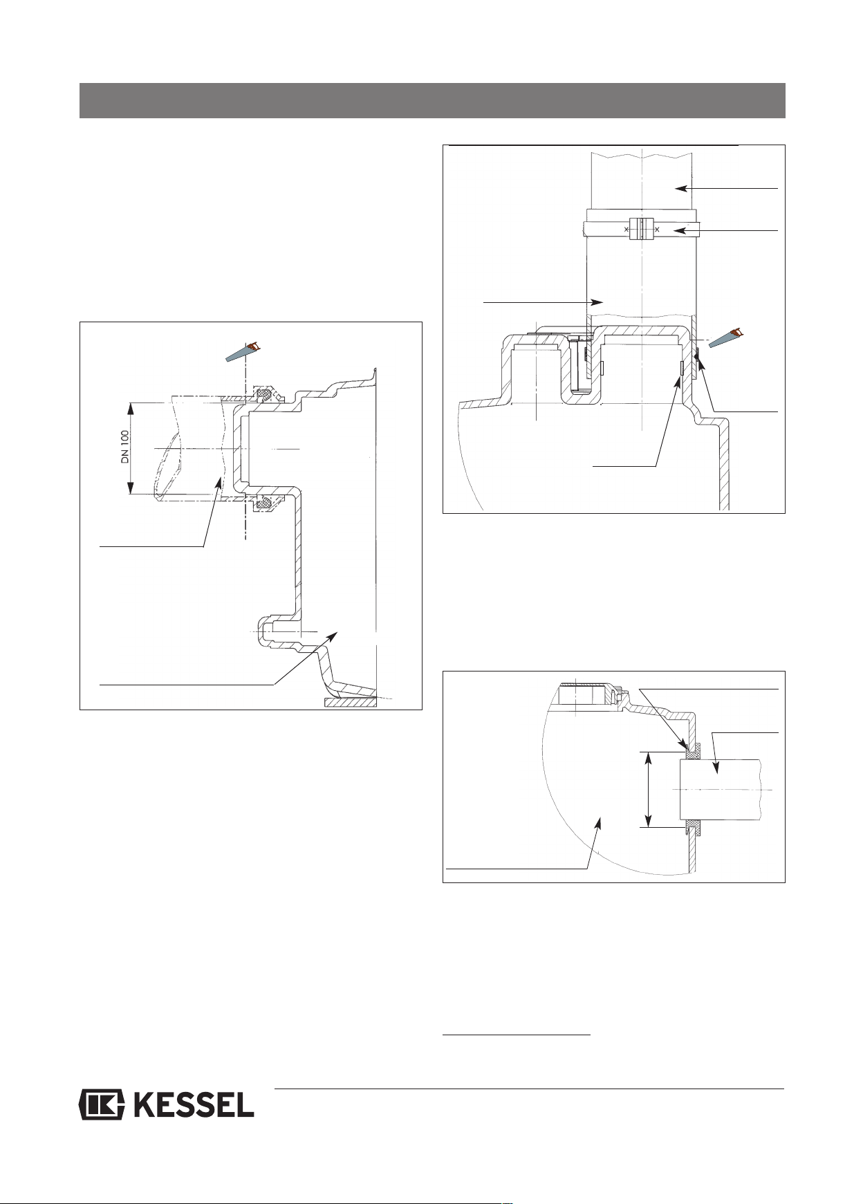
. Use of existing moulded connecting pieces on the
I
tank
(for connection of inlet pipe, ventilation and manual
diaphragm pump according to Fig. A and B) by cutting off
the "front cap" as shown in Fig. C.
Ventilation DN 70 (Da=75mm)
Inlet
connection
DN 100
(Da=110mm)
4.1 Fitting the collecting tank
Umaintenance work on the lifting stations, they must always
be installed in such a way that there is sufficient access to all
areas of the lifting station and replaceability of all components is guaranteed. According to DIN 1986, there must be
at least 60 cm space all round the system (on all sides and
above it) to meet this requirement.
The system must be set up at the appropriate spot in the
room, aligned horizontally and placed on practical sound-insulating material (available as an accessory from KESSEL).
The brackets, screws and dowels must be used to fix the lifting station to the floor to prevent movement or twisting.
Attachment bracket
Tank-lifting station
attachment
Insulation mat
(optional)
Floor
Closure manual diaphragm
pump DN 32 (Da=40mm)
Abb. A: Single System
Inlet connection
DN 100 (D
a
=110mm)
Ventilation DN 70 (Da=75mm)
Closure manual diaphragm pump DN 32 (Da=40mm)
Abb. B: Twin System
Floor
9
Page 10
4. Installation and assembly
A standard plastic pipe muff can be pushed over the connecting piece (see Fig. C).
Alternatively, the connection of a plastic pipe with DN 100 for
the inlet or DN 70 for ventilation can be carried out using
connection clamps or rubber hoses with hose clamps*. To
revent the high tension forces leading to deformation at the
p
connecting piece, a suitable supporting ring* must be pushed into the upper end of the connecting piece (see Fig. D).
Saw off
connecting pieces
Transition
hose piece
Supporting ring
ipe connection
P
H
clamps
Saw off con-
necting pieces
Hose
clamp
ose
Inlet connection
Tank-lifting station
Abb. C:
Abb. D:
II. Connections attached to the pre-scored areas at
the side (for inlet pipe or manual diaphragm pump) using
bore hole with saw cap*, fitting of a suitable greases seal*
and insertion of a suitable plastic pipe (see Fig. E)
Pipe duct seal
Pipe connection
Opening drilled
Tank-lifting station
Abb. E
* KESSEL accessory part
10
Page 11
4. Installation and assembly
IMPORTANT
In the case of all the connections drilled at the side it must
be remembered that the level control is adjusted in such
a way that during normal operation the water level in the
ontainer only reaches up to or just below the lower edge
c
of the moulded inlet pipe connecting piece on the side.
For this reason, a respective water level will result in all
pipes that are connected lower down. In the case of inlet
ipes this means that dirt deposits cannot be excluded
p
and may lead to the pipe becoming blocked in extreme
cases.
ressure pipe are available as accessories:
p
DN 80 backwater flap made of cast iron (art. no.: 206-199)
N 100 backwater flap made of cast iron (art. no.: 206-198)
D
Aerating device (art. no. 206)
A shut-off valve must be installed in the pressure pipe on site
in accordance with EN 12056. For this, we recommend the
on-return valves for mono systems (art. no. 28683) and for
n
duo systems (art. no. 28694) from the KESSEL range of ac-
essories.
c
4.3. Level measurement
l Inlet pipe
The inlet pipe must be laid at a gradient to the KESSEL lifting station in accordance with DIN 1986 and be routed as
straight as possible.
Connection to the tank can be carried out as described under
section I or II above.
The ventilation pipe sets up pressure compensation to the
fresh air for the air flowing into or out of the system during
emptying or filling. According to DIN 1986 it must be laid at
least as size DN 70 for these lifting stations, and must be routed over the roof to avoid odour pollution.
Connection to the tank can be carried out as described under
section I or II above.
l Pressure pipe
The pressure pipe for directing the soiled water into the sewage system must be connected directly to the respective
pressure pipe connection. According to the regulations of EN
12056, the pressure pipe must be routed above the backwater level and connected to a ventilated basic or collecting
pipe.
The rubber hose included in the scope must be pushed about
4 cm over the pressure connecting piece at the pressure
connection and fixed in place using a hose clamp as a means
of acoustic insulation and to prevent transmission of forces.
Connection of the rubber hose is not an interlocking connection. It must be set up on site using brackets.
The pressure pipe must be connected (see above) in such a
way that no forces are transferred to the system and there is
no direct contact with the building (structure-borne noise). No
other draining elements may be connected to the pressure
pipe.
Air-tightness and material strength must be guaranteed
under pressure load, too. This must be checked during initial operation.
The pressure pipe must not be connected firmly to the building to prevent pressure blows. When cast metal or steel
pressure pipes with low absorption properties are used, a
pressure blow muffler must be included in the pressure pipe
from pumping heights from 5 m.
Backwater flaps to avoid pressure blows for installation in the
CAUTION:
Before commencing any work on the switchgear, the
pump or the level control, the master switch and cut-outs
must be switched off and secured against being reconnected.
4.3.1 Systems from model year 01/2010
Level measurement takes place using pressure sensor and
submersible pipe. The transparent air hose must always be
routed rising to the switch unit so that no condensation can
collect in the air hose.
Perfect function is only guaranteed when permanent pressure compensation takes place between the switch unit and
lifting station. Excess air hose lengths must be shortened.
Extensions of the air hose up to 20 m are possible.
The switching levels are pre-set and can be changed using
the switch unit. More detailed information is available from
KESSEL Customer Services.
4.3.2 Systems up to model year 01/2010
Level measurement is carried out using a pressure diaphragm switch that is connected to the switch unit via an electric cable inc. air hose. Contact KESSEL Customer Services for information about setting the switching level.
11
Page 12
5. Electrical connections
CAUTION:
Only qualified electricians may carry out the work on electrical equipment described below. Before any work is
carried out on the switch unit, the pump or level control,
the main switch and fuses must be switched off, i.e. be voltage-free and secured against being switched back on
again
.1 General instructions
5
An external main switch must be installed for the electric
switch unit that can be used in an emergency to switch off all
the downstream circuits independently of the control unit.
This must be assigned clearly to the switch unit.
All connected cables must be strain-relieved.
Screw connections not used must always be sealed properly.
IMPORTANT:
All the cables connected to the electrical switch unit must
be fixed in place using suitable measures (e.g. cable ties)
so that they do not cause a hazard in the 1-error case, i.e.
if a connection becomes loose..
.3 Installation, wiring
5
he pump cables and control cable have a standard length
T
of 5 m. Extension to max. 20 m is possible on site, but must
be done using a VDE-conform connection.
NOTE (applies to pressure diaphragm switches up to model
ear 01/10)
y
The cable on the pressure level switch is a special cable with
an air hose in the centre for compensating pressure for the
pressure sensor in the lifting station to the atmosphere. The
following must always be observed:
– The cable may be cut off at any point but must never be
extended. Special lengths of this cable can be ordered directly from KESSEL.
– The cable must be routed at a constant gradient from the
switch unit to the lifting station.
For this reason, excess lengths must not be rolled up, the
cable has to be shortened to fit.
– The respective screw connection at the switch unit may be
tightened with a maximum torque of 2.5 Nm. Greater torques
can lead to the air hose being squeezed.
– Deviations from these instructions can lead to functional failure of the pressure sensor and thus the
whole system!
Please heed national and local safety regulations. If these
are not observed, personal hazard may be the result. In addition, no liability or warranty will be granted. After work has
been completed, the housing cover must be sealed properly
again.
5.2 Mounting the switch unit
Screw the housing cover with max. 1 Nm. Install the switch
unit provided in a frost-free, dry, flood-proof and well-ventilated room. The switch unit has been designed for vertical
wall-mounting on a solid base. Sufficient air circulation must
ensure excessive inside temperatures develop. The unit is
mounted using 4 screws (Ø 6 mm) at the corners of the housing (drilling template in the packaging box). The attachment
holes are accessible after the cover has been opened.
12
Page 13
5. Electrical connections
he individual connection jobs are listed in the following table and in the connection diagrams on pages 27 and 29. The ex-
T
planations in chapter 8, Electric switch unit, must also be heeded (position of the control elements, view of the inside of the
witch unit).
s
INGLE SYSTEM- Heed safety instructions!
S
Work to be done Switch unit
oth batteries (2 x 9V block) must
attery connection
B
(rechargeable batteries up to year 12/09)
Mains connection
B
be connected on the board.
• Connect the mains supply cable L1
/ L2 / L3 / N / PE at the terminal
block using screw connection.
• N and PE always have to be
connected.
• The mains supply cable must have
an all-pole main switch on the installation side that is clearly assigned to the control.
• The pre-fuse prescribed on the installation side must not exceed 16
A per phase.
• The control can be damaged or destroyed if connection is not carried
out correctly.
from model year 01/10 Switch unit up to model year 12/09
The rechargeable battery (1 x 9V block) must
•
e inserted into rechargeable battery fixture.
b
• Connect the mains supply cable L1 / L2 / L3 /
N / PE to the upper level of the grey mains
connection terminal block, heeding markings
(printing on the board).
• N and PE always have to be connected.
• The mains supply cable must have an all-pole
main switch on the installation side that is
clearly assigned to the control.
• The pre-fuse prescribed on the installation side
must not exceed 16 A per phase.
• The control can be damaged or destroyed if
connection is not carried out correctly.
Motor supply cable
Motor temperature sensor
Level measurement
Connect the motor supply cable
•
U/V/W to the connector in the right direction in the lower screw terminals
T1 / T2 / T3. The direction of rotatio
of the motor must be heeded.
• PE must be connected with TF1
and TF2 to the terminal block on
the board underneath the motor
protection switch.
• Wire 4 of the motor supply cable
must be connected to the lowest
terminal of the terminal block TF2
TF1.
Wire 5 of the motor supply cable
must be connected to the central
terminal of the terminal block TF2
TF1. The input TF2 is bridged using
a 2-pole jumper, i.e. the central terminal is doubly occupied. Jumper
must not be removed!
Connection to the pressure sensor
The transparent air hose must always be routed rising to the switch
unit. The air hose must be screwed
tight to the connection provided on
the switch
• Connect the motor supply cable U/V/W to the
ABB connector B6-30-10 left of the motor protection switch in the right direction in the lower
n
screw terminals T1 / T2 / T3. The direction of
rotation of the motor must be heeded.
• Connect PE to the lower level of the grey
mains connection terminal block, heeding the
markings (printing on the board).
• Input TF: Wire 4 of the motor supply cable
must be connected on the right at TF input,
wire 5 on the left at TF input.
• Input E7: The jumper must be left.
Level inputs (ON/ALARM)
• The cable must always be routed rising to the
switch unit.
• The cable ends of the pressure level switch
must be connected to the respectively marked
terminals (white wire on the right, brown wire
on the left to "on" input, green wire on the right
and yellow wire on the left to "alarm" input).
13
Page 14

5. Electrical connections
SINGLE SYSTEM- Heed safety instructions!
Work to be done Switch unit from model year 01/10 Switch unit up to model year 12/09
• The terminal block of the level inputs must
not be connected with any other circuit.
• The terminals are marked with switch
ymbols.
s
• The outputs N / L1 (2 each) are provided to
supply external warning devices/equipment
with power via the "malfunction" and "alarm"
relays. They must not be used for other purposes.
• Maximum permissible current is 2A.
Outputs
"Malfunction" and
"alarm / warning"
The "malfunction" and "warning"
messages are issued via a relay
(changeover contact) without protective circuit. Inductive loads must
be dejammed externally. The quiescent state (currentless) of the relays
is printed on the board. It means
"malfunction" and "warning" message is switched on.
• 42 V DC/ 0.5 A
• The "malfunction" and "alarm" messages
are issued via a relay (changeover contact)
without protective circuit. Inductive loads
must be dejammed externally. The quiescent state (currentless) of the relays is printed on the board. It means "malfunction" and
"alarm" message is switched on.
• The relay contacts do not have any internal
connection to any kind of supply or operating
voltages of the control unit and are safely separated from these up to a working voltage
of 300 V according to Table D.10 of the standard EN 61010 (excess voltage category 2
and degree of soiling 2).
• The relays have been designed for switching
230 V / 2 A. Suitable measures must be
taken to restrict the current externally to this
value.
• The relays must not be used to switch different phases. The phase may deviate from L1
however.
14
Page 15
5. Electrical connections
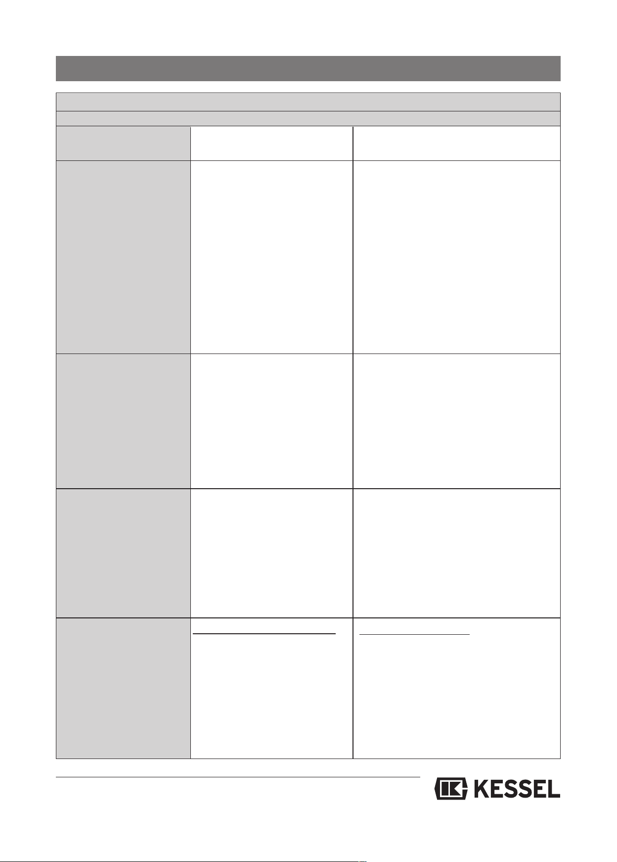
TWIN SYSTEM- HEED SAFETY INSTRUCTIONS!
ork to be done Switch unit
W
from model year 01/10 S
witch unit
up to model year 12/09
Battery connection
rechargeable batteries up to 12/09)
(
Mains connection
Motor supply cable
• Both batteries (2 x 9V block) must
be connected on the board.
Connect the mains supply cable L1 /
•
L2 / L3 / N / PE at the terminal block
L1 / L2 / L3 / N / PE using screw
connection.
•
N and PE always have to be connected.
• The mains supply cable must have
an all-pole main switch on the installation side that is clearly assigned to
the control.
• The pre-fuse prescribed on the installation side must not exceed 16 A
per phase.
• The control can be damaged or destroyed if connection is not carried
out correctly.
• The motor supply cables 2 x U/V/W
must be connected to the connectors
in the right direction in the lower
screw-type terminals T1 / T2 / T3
(pump 1 left, pump 2 right). The direction of rotation of the motor must
be heeded.
• PE must be connected with TF1 and
TF2 to the terminal block on the
board underneath the motor protection switch.
• Der Akku (1 x 9V-Block) ist in die Akkuhalterung einzustecken.
• Connect the mains supply cable L1 / L2 / L3
/ N / PE to the second level from the bottom
of the mains through terminals, heeding mar-
ings (printing on the board / colours).
k
• N and PE always have to be connected.
• The mains supply cable must have an allpole main switch on the installation side that
is clearly assigned to the control.
• The pre-fuse prescribed on the installation
side must not exceed 16 A per phase.
• The control can be damaged or destroyed if
connection is not carried out correctly.
• The motor supply cables 2 x U/V/W must be
connected to the ABB connector B6-30-10
below the motor protection switch in the right direction in the lower screw-type terminals T1 / T2
/ T3 (pump 1 left, pump 2 right). The direction of
rotation of the motor must be heeded.
• Connect PE to the respective upper level of the
mains through terminals, heeding the markings
(printing on the board / colours).
• The motors must be dejammed externally if ne-
cessary.
Motor temperature sensor
Level measurement
PUMP 1/2: Wire 4 of the motor supply cable of pump 1 must be connected to the lowest terminal of the terminal block TF2 TF1. Wire 5 of the
motor supply cable must be connected to the central terminal of the terminal block TF2 TF1.
• Input TF2 pump 1/2: The jumper
must be left.
Connection to the pressure sensor
The transparent air hose must always
be routed rising to the switch unit. The
air hose must be screwed tight to the
connection provided on the switch
unit.
• Input TF1: Wire 4 of the motor supply cable
of pump 1 must be connected on the right to
input TF1, wire 5 of the motor supply cable
on the left to input TF1.
• Input TF2: Wire 4 of the motor supply cable
of pump 2 must be connected on the right to
input TF2, wire 5 of the motor supply cable
on the left to input TF2.
• Input E7: The jumper must be left.
• Input E8: The jumper must be left.
Level inputs (ON/ALARM)
• The cable must always be routed rising to the
switch unit.
• The cable ends of the pressure level switch
must be connected to the respectively marked terminals (white wire on the right, brown
wire on the left to "on" input, green wire on
the right and yellow wire on the left to "alarm"
input)
• The terminal block of the level inputs must
not be connected with any other circuit.
15
Page 16
5. Electrical connections
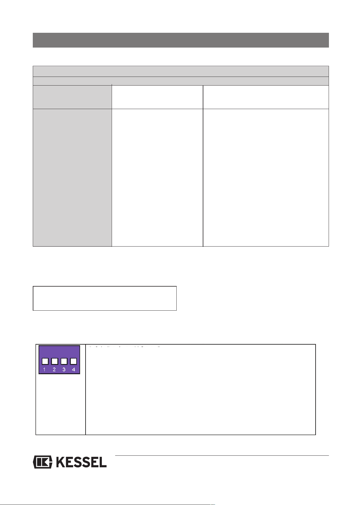
TWIN SYSTEM- HEED SAFETY INSTRUCTIONS!
Work to be done Switch unit from model year 01/10 Switch unit up to model year 12/09
The terminals are marked with switch symbols.
•
Outputs
Malfunction" and
"
"warning"
5.4 Checks
- on the setting of the motor protection switches
• The "malfunction" and "warning"
messages are issued via a relay
(changeover contact) without
protective circuit. Inductive loads
must be dejammed externally.
The quiescent state (currentless) of the relays is printed on
the board. It means "malfunction" and "warning" message is
switched on.
42 V dc/ 0,5 A
• The "malfunction" and "alarm" messages are issued via a relay (changeover contact) without
protective circuit. Inductive loads must be dejammed externally. The quiescent state (currentless) of the relays is printed on the board. It
means "malfunction" and "alarm" message is
switched on.
• The relay contacts do not have any internal connection to any kind of supply or operating voltages of
the control unit and are safely separated from these
up to a working voltage of 300 V according to Table
•
D.10 of the standard EN 61010 (excess voltage category 2 and degree of soiling 2).
•
The relays have been designed for switching 230 V
/ 2 A. Suitable measures must be taken to restrict
the current externally to this value.
• The relays must not be used to switch different phases. The phase may deviate from L1 however.
The motor protection switches must be set to the
values for rated current of the respective pumps
as specified in section 3.
5.5. Configuration of switch unit (from model year 01/10)
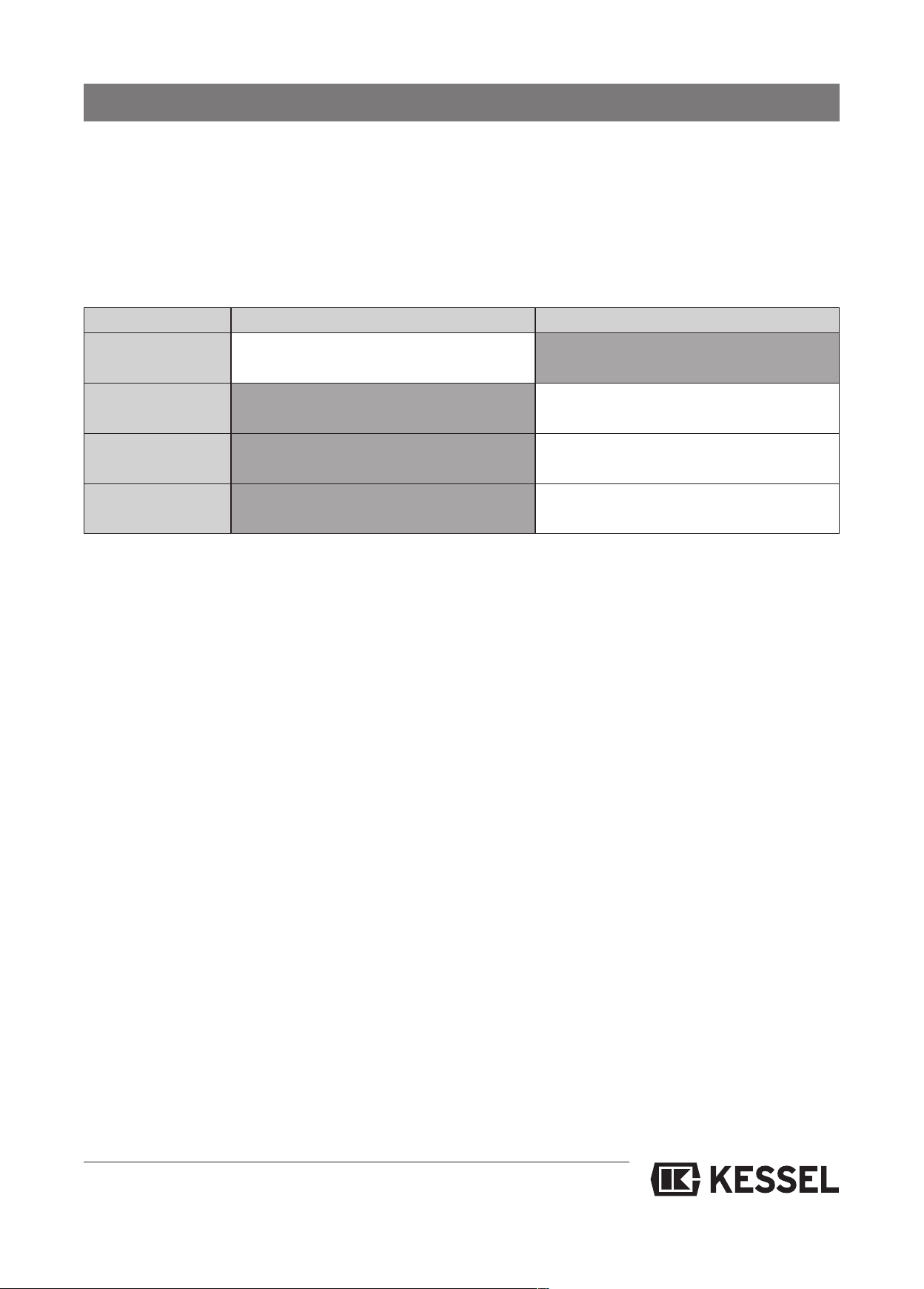
The DIP switch is located at the top right of the PCB in the switch unit and has four setting possibilities
1. Switch: Sensor selection
- Switch up: Level measurement using float switcher
- Switch down: Level measurement using air pressure switch
2. Switch: Level heights
- Switch up: Underground pumping stations (with submersible pumps)
- Switch down: Lifting stations (using air pressure switch)
3. Switch: Configuration tables (only for service partners)
4. Switch: Anti-blocking system
- Switch up: Anti-blocking system off
- Switch down: Anti-blocking system on
16
Page 17
5. Electrical connections
5.6 Configuration of switch unit (up to model year 12/09)
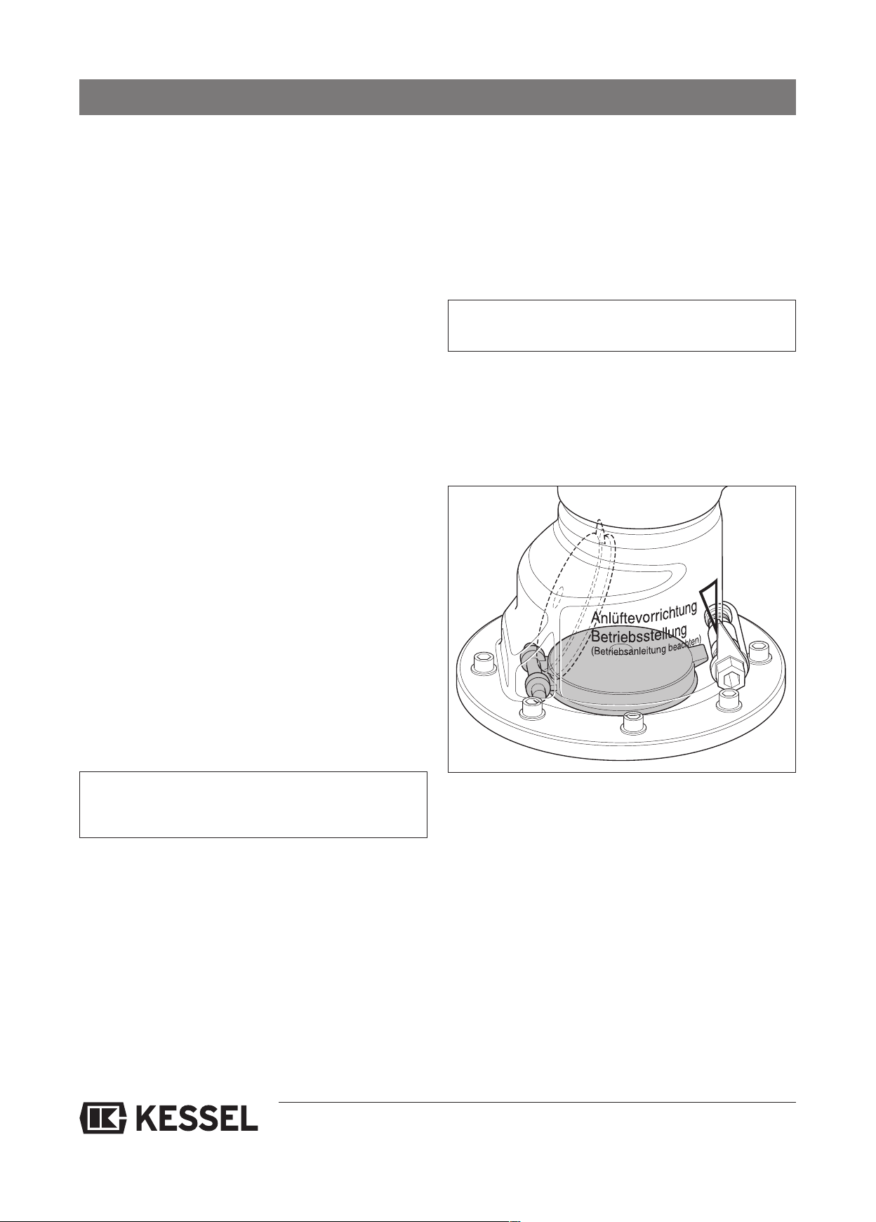
Configuration of the control is carried out in the factory using switches S601 ... S604 between the terminal blocks of the level
inputs and thermal protection input. For safety reasons, these must be checked according to the following descriptions.
Pre-settings or reference settings are highlighted grey.
- Basic setting is carried out using switch S604 (4-way DIP switches with 2 positions ON / OFF each).
- Deviating settings are not allowed.
up to year 12/09
S604 / 1
S604 / 2
S604 / 3
S604 / 4
ON
Run-time controlled System
(wastewater lifting system)
Submersible pump
without OFF level switch
Rotary field/phase monitoring
on
Anti-blocking function
on
OFF
Level-controlled
(submersible pump system)
Submersible pump
with OFF level switch
Rotary field/phase failure monitoring
off
Anti-blocking function
off
system
17
Page 18
6. Initial operation
.1 General instructions
6
nitial operation
I
Initial operation must be carried out by a qualified expert, with
the direct supplier of the wastewater lifting station responsible for his availability. During initial operation, a test run with
ater is required over at least two switching cycles. During
w
the test run, dry running must be avoided. Before, during and
fter this test run, the following must be checked:
a
a) The electric fuse protection of the wastewater lifting stati-
on according to IEC or local regulations
b) The direction of rotation of the motor
c) The gate (actuation, open position, air-tightness)
d) The switching and setting of switching heights in the
collecting tank, in as far as these are not pre-set by the
manufacturer
e) Air-tightness of the system, fittings and pipes
f) Check on operating voltage and frequency
g) Functional test on the backflow preventer
h) Malfunction warning device
i) Attachment of the pressure pipe
j) Motor protection switch; check by briefly screwing indivi-
dual fuses out (two-phase run)
k) Oil level (if oil chamber exists)
l) Pilot lamps and counters
m) Functional test for any manual pump that may be instal-
led.
Initial operation must be documented in writing, whereby important data e.g. setting of the motor protection switch and
status of operating hours counter must be noted.
heck the system installation/cabling carefully before you
C
put the system into operation. Is the protective earthed con-
uctor working? Have the relevant standards/guidelines
d
been heeded, particularly with a view to the potentially explosive area?
Do not put the system into operation if there is any damage
o the motor, switch unit or cables visible.
t
Always follow the safety instructions in chapter 1 of this ma-
ual.
n
IMPORTANT:
All screw connections must be checked for a tight fit.
6.2 Pressure outlet connecting pieces
The pressure outlet connecting pieces of the lifting stations
are equipped with a backwater flap with aerating device as
standard for each pump. The aerating device must always be
in operating position (see Fig. 1).
This initial operation may only be carried out by authorised
specialist staff.
DIN 1986, part 3, must be heeded during the initial operation of lifting stations.
CAUTION:
Before initial operation the inlet pipes and the pumps must
be cleaned of solid materials such as metal, sand etc.
Before initial operation the pump must be filled with pumping
fluid up to the height of the ventilation bore hole of the pump
housing.
The pump must not suck in any air!
After the complete and correct installation of the complete system and all the additional parts as well as the pipe and electrical installations, the system can be put into operation.
Any shut-off valves must be opened.
Make sure before you put the system into operation that the
nominal voltage and type of current specified for the system
correspond to the nominal voltage and type of current on site.
Fig. 1
The flap (dotted line) is opened exclusively by the pumping
flow of the pump.
6.3 Operating the switch unit (from model year 01/10)
As soon as the network connection has been set up, initialisation takes place immediately, i.e. the system undertakes a
self-test. After this test, the system is ready for operation
(mains LED lights up).
The acoustic alarm can be switched off by pressing the alarm
LED. The pump(s) can be switched on manually by pressing
the pump key twice.
18
Page 19
6. Initial operation
.4.1 Operating the switch unit
6
6.4.1 "Automatic" operating model
) Single system
a
The basic function is carried out when the operating mode
switch is set to "auto" and there is no indication of a malfunction (see chapter 9, Switch unit). As the (soiled water) level
ises in the tank, the level switch "on" closes. After the "on"
r
switched has closed, the switch-on delay time begins (see
section 5.7, Configuration of switch unit), after which the
pump is switched on. The level in the tank decreases through
the pump operation so that the "on" level switch opens again.
After the "on" switched has opened, the run-on time begins
(see section 5.7, Configuration of switch unit), after which the
pump is switched off.
If the current pump running time exceeds the configured
value of the maximum running time limit, the pump is switched off. At the same time, a malfunction message is issued
by the red LED "run time" lighting up permanently and via the
"malfunction" relay output. The malfunction message (LED
and relay) remain stored until the "alarm reset" key is actuated, and the pump can only be restarted once this has taken
place.
b) Twin system
The basic function is carried out when both operating mode
switches are set to "auto" and there is no indication of a malfunction (see chapter 9, Switch unit).
p to model year 12/09)
(
u
hen the maximum running time limit has been exceeded,
W
the malfunction message and switch-off of the respective
pump take place as with the single system. The respective
pump can only return to operation when the "alarm reset" key
has been actuated.
n as far as one pump leaves "auto" control (on account of
I
the running time limit being exceeded, a malfunction, through
respective position of the operating mode switch), the remaining second pump is operated analogue to the "auto"
control of a single system, independently of the other pump.
6.4.2 Operating mode "0" (up to model year 12/09)
When the operating mode switch is in the "0" position, the
(respective) pump is switched off, independently of all input
signals. The display elements remain ready for operation.
6.4.3 Operating mode "manual" (up to model year 12/09)
In the "manual" operating mode the (respective) pump is or
remains switched on, independently of the existing water
level in the tank, until this operating mode is switched off
again.
CAUTION:
Running the pump(s) without water will lead to reduced cooling and increased wear of the pump motor.
Excessive dry running of the pump(s) longer than 5
minutes can thus lead to irreparable damage to the
pump. Such damage is not covered by the warranty.
Alternating operation
As the (soiled water) level rises in the tank, the level switch
"on 1" closes. After the "on 1" switched has closed, the
switch-on delay time begins (see section 5.7, Configuration
of switch unit), after which one pump is switched on. The
level in the tank decreases through the pump operation so
that the "on 1" level switch opens again. After the "on 1" switched has opened, the run-on time begins (see section 5.7,
Configuration of switch unit), after which this pump is switched off. Next time the "on 1" level is reached, the other
pump is switched on.
Parallel operation
As the (soiled water) level rises in the tank, the level switch
"on 1" closes. After the "on 1" switched has closed, the
switch-on delay time begins (see section 5.7, Configuration
of switch unit), after which one pump is switched on. If the
water level continues to rise, the second pump is switched
on (after the delay time) in addition if the "on 2" level is exceeded. This parallel pump operation continues until the "on
1" level switch opens again and the run-on time has expired.
6.5 Functional test
The different functions of the overall system depending on
the water level in the tank must be checked in a one-off test
using the corresponding water filling levels in the tank. The
tank must be filled via the connected inlet pipe.
19
Page 20
7. Inspection and maintenance
he system must be checked once every month by the ope-
T
rator through observation of the switching routine for opera-
ional ability and leaks.
t
CAUTION:
Disconnect the unit from the mains during all mainte-
ance work! Heed safety instructions!
n
ll the servicing and maintenance work described
A
below may only be carried out by authorised qualified
personnel.
Repairs may only be carried out by the manufacturer
or his authorised service partner.
DIN 1986, part 3, must be heeded during maintenance work
on lifting stations. Maintenance work must be carried out regularly by authorised qualified staff.
IMPORTANT:
All screws may only be tightened with a maximum torque
of 3 Nm.
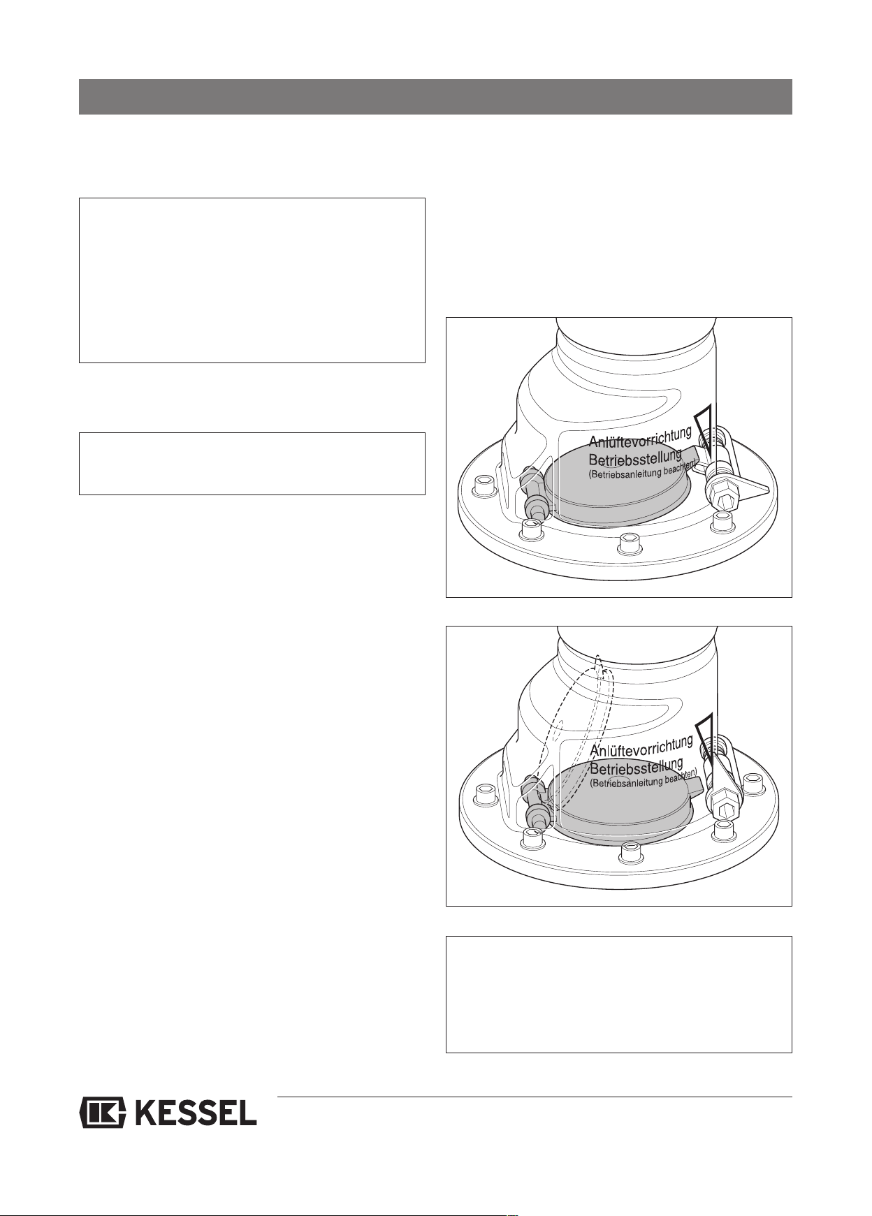
.2 Notes on the aerating device
7
he aerating device can be used to completely empty the
T
pressure pipe through manual lifting of the backwater flap on
the lifting system. To do this, an Allen key size 8 or openended spanner size 15 must be used to hold the flap opener
urned (see Fig. 2) as long as necessary until the pressure
t
pipe is empty. Then the flap opener must always be returned
o its initial position or the marked operating position (see
t
Fig. 3).
The following tasks have to be carried out:
• Visual inspection of the complete system, pumps and fitting
parts
• Thorough cleaning of the complete system and the pump
• Check on the complete system and pump housing for ex-
ternal damage and visible wear
• Check on the pump for free movement, wear and deposits
• Check the connection cables for mechanical damage and
wear
• Check the seal connections for air-tightness and replace
the seal (e.g. O-ring) if there any indications of wear
• Insulation test on the pump motor
• Check non-return valve for function if appropriate
• The backwater flap must be replaced after 2 years of ope-
ration.
7.1 Notes on the pump
The pump should be checked at regular intervals. If operational noises increase, pumping capacity decreases or there
are vibrations in the pipeline system, the pump housing and
impeller must be checked for any stubborn soiling or wear.
To do this, the motor unit must be loosened at the four attachment screws (refer also to section 10.2.1 or 10.2.2) and removed from the pump housing.
When checking the pump housing, care must be taken that
the ventilation bore hole is kept open under all operating conditions.
Fig. 2
Fig. 3
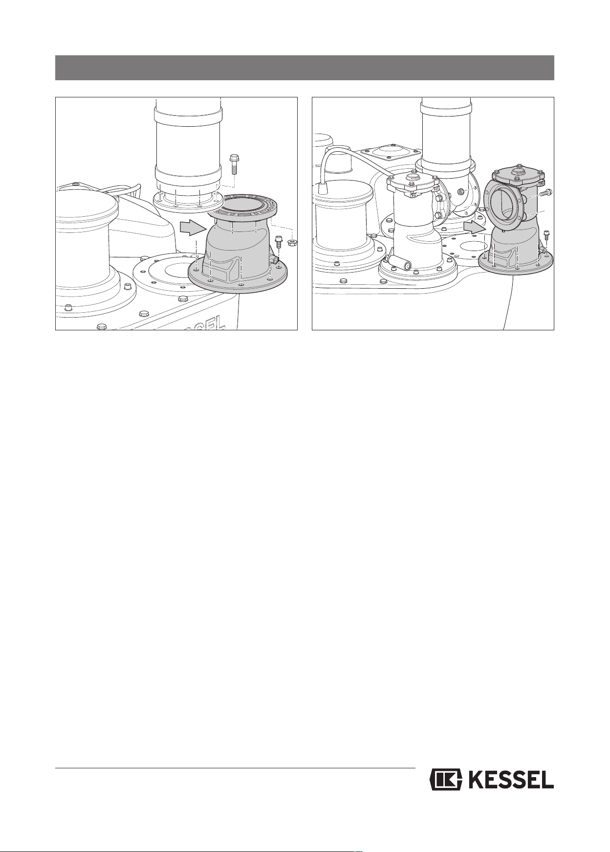
Note:
The complete flap housing can be removed for cleaning
and maintenance purposes (see Fig. 4+5) by loosening
the screw connections on the lower and upper flange of
the flap housing. The pressure pipe must have been
blocked off and emptied first, of course.
20
Page 21
7. Inspection and maintenance
Fig. 4 Fig. 5
7.3 Notes on the electric switch unit
• The battery / rechargeable battery is a wearing part and
should be checked and changed if necessary once a year
if possible. When changing the batteries, make sure you
dispose of them properly, with the environment in mind.
They may only be replaced by batteries of the same type.
• The contactor is a wearing part and should be checked and
changed if necessary once a year if possible. When changing the batteries, make sure you dispose of them properly,
with the environment in mind. They may only be replaced
by batteries of the same type.
• After maintenance work, the cover plate and transparent
housing cover (up to model year 12/09) must be attached
properly again (contact protection!).
• Repairs may only be carried out by the manufacturer/service partner.
21
Page 22
8. Malfunctions and troubleshooting
he system must be checked once every month by the operator through observation of the switching routine for operatio-
T
nal ability and leaks.
8.1 General malfunctions
Malfunction Cause Remedial measure
Pumps do not start
1
perating mode switch is not set to
O
"auto" (only up to model year 12/09)
Motor protection switch has triggered, motor is blocked
Motor turns sluggishly
1 or 2 phases have no current
Control fails on account of heavy
fluctuations in the mains power
supply
et switch to "auto"
S
Remove pump; eliminate blockage (object) in
the impeller or housing area
Maintenance / repair by Customer Services
Check fuses and power supply
cables
Retrofit battery in the switch unit and
inform power supply company.
2 Pumps are running,
Alarm level is reached /
is indicated
3 Pumps run roughly or loud
and LED "phase/rotary field"
lights up (only up to model
year 12/09))
3 Pumps run roughly or loud
and LED "phase/rotary
field" does not light up (only
up to model year 12/09)
Pressure sensor not airtight or PE
hose not connected
System is overloaded
Too little pumping capacity.
Aeration device not in operating position
Wrong direction of rotation for
motor
In the case of twin systems, both
motors are rotating the wrong way
Reduced capacity through
damage
Wrong direction of rotation for
motor
In the case of twin systems, both
motors are rotating the wrong way
Check all screw connections for air-tightness
Check whether there is a short-term increase in
wastewater occurrence; if possible do not use
drainage points temporarily or divert wastewater elsewhere if possible
• Eliminate object in the impeller or housing
area
• Remove the object from the pressure fitting or
pressure pipe
• Pumps are worn, have them replaced
• Wrong lifting station design, clarification
through KESSEL Customer Services
Put aeration device into operating position
Check direction of rotation, if incorrect swap
2 phases of the supply cable
Swap 2 phases in the supply cable of the
switch unit
Check pump(s) and motor(s); have damaged
parts replaced by Customer Services
Check the direction of rotation, if incorrect swap
2 phases of the motor supply cable (see section 5.5)
Swap 2 phases of the motor supply cables of
the switch unit
4 Wastewater is not drained
off, backwater at the lowest
draining points
Systems not switched on
Power supply cable to the switch
unit without current
Level control malfunction
Inlet pipe to the system blocked
Set switch to automatic
Check fuse. Check current supply.
Check soiling, switching points and function of
the level control
Clean inlet pipe
22
Page 23
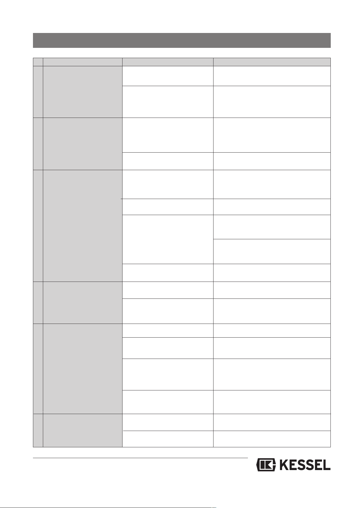
8. Malfunctions and troubleshooting
törung Ursache Abhilfemaßnahme
S
5 System suddenly
runs loudly
6 Putrid smell
Acrid smell
Inlet gate to the system (if existent) not
opened or not opened completely
Wastewater temperature too high
ver a longer period (15 min), lea-
o
ding to restricted suction capacity
of the system
Phases switched through work on
he domestic power supply
t
Damage to the pump parts through
objects
Object in the pump
Leaks in the lifting station
Pump not airtight
Motor(s) too hot, overloaded
Open inlet gate completely
Reduce wastewater temperature
checking the direction of rotation
Check pump, have it repaired or replaced by
Customer Services if necessary
Remove the object, check pump for damage
and replace if necessary
Check ventilation, inlet and pressure lines as
well as covers for air-tightness and eliminate
leaks
Check pump, have it repaired or replaced by
Customer Services if necessary
Check motor and pump to make sure they are
running easily, check system for switching malfunctions (particularly motor protection switch)
7 System runs too often, swit-
ches on for no reason
8 System does not switch or
has a variety of different
switching malfunctions
9 Pumping capacity too low
Contactors too hot on account of
switching malfunctions
Supply quantity too high through
external water or similar
Backwater flap faulty, wastewater
runs out of the pressure pipe back
into the system
Foam formation in the system
Tank or pumps are blocked by
grease being discharged in large
quantities
Level control ventilation blocked
Level control soiled; level pressure switch set incorrectly or faulty
Rotary field incorrect
System switched on and off too often on account of high inlet quantities, clarification with
KESSEL customer services
Check system for switching malfunctions.
Find and eliminate the causes
Check backwater flap (integrated in the pressure outlet connecting piece on every pump),
clean it and replace any damaged parts
Reduce amounts of washing powder and detergents used
Clean the whole system, check grease
discharge
Check cables between the switch unit and level
control for kinks and correct routing (even gradient), correct or replace if necessary
Remove the level control, clean submersible
pipe, check pressure switch and adjust if necessary
Swap mains wires (malfunction message at the
switch unit)
Wrong direction of pump rotation
23
Check pump wires for correct connection
Page 24
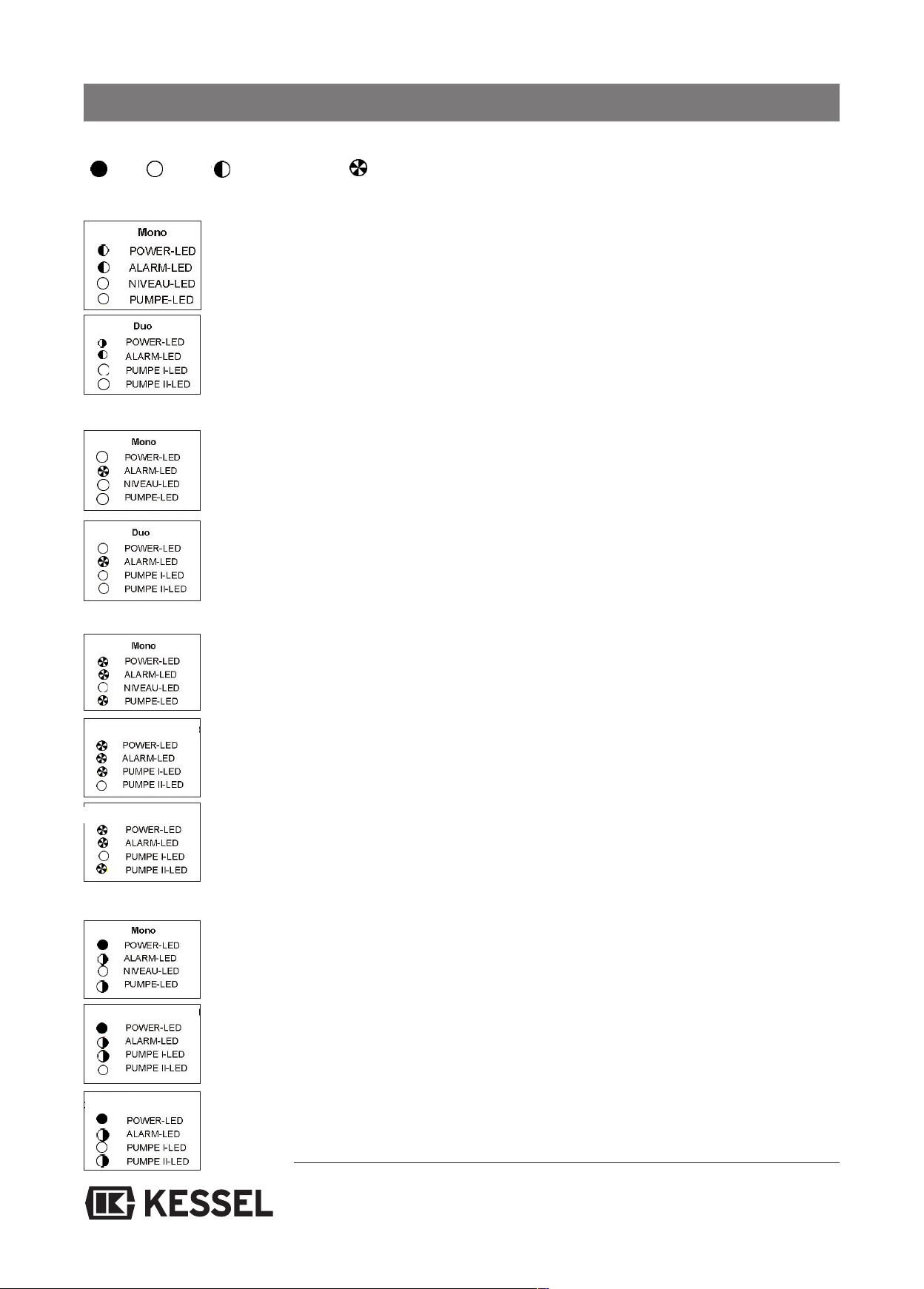
8. Malfunctions and troubleshooting
alfunction messages / remedial measures (from model year 01/10)
M
= lit = off
Battery fault
Power failure (battery operation)
l =
= flashing slowly ❍ = flashing quickly
- Acknowledge alarm and alarm key
- Check if batteries are connected
Replace discharged batteries
-
- After acknowledging the signal tone, press the alarm key again
--> Switch unit continues to work without batteries
--> No protection function during power failure
- Check whether power has failed in the whole room / building
- Check fuses / check fault-current circuit breaker
- Check mains cable for fault
- Check microfuse in the switch unit
(only use fuses with the same nominal capacity and triggering characteristics).
Motor fault
Cause: TF1, TF2, MSS
Remedy: --> Check motor protection switch 1/2
--> Lower winding temperature switch has triggered
--> Automatic reset when motor has cooled must be acknowledged
Duo Pump 1
Duo Pump 2
Running time limit fault/ running frequency limit fault
- Running frequency limit fault: one pump starts up more often than 20 times in 3 minutes
--> Check air hose between submersible pipe/plunger and switch unit
for water inclusions
--> Check submersible pipe/plunger for blockage
Duo Pump 1
--> Check supply pipe, check pumping capacity
--> Check backwater flap
using the alarm key.
--> In the case of lifting stations jumper TF2 faulty/not installed
Replace/install jumper
Duo Pump 2
- Running time limit fault: Pump has been running for longer than 240 minutes at a time
--> Check air hose between submersible pipe/plunger and switch unit for water inclusions
--> Check submersible pipe/plunger for blockage
--> Check supply pipe, check pumping capacity
--> Check backwater flap
24
Page 25
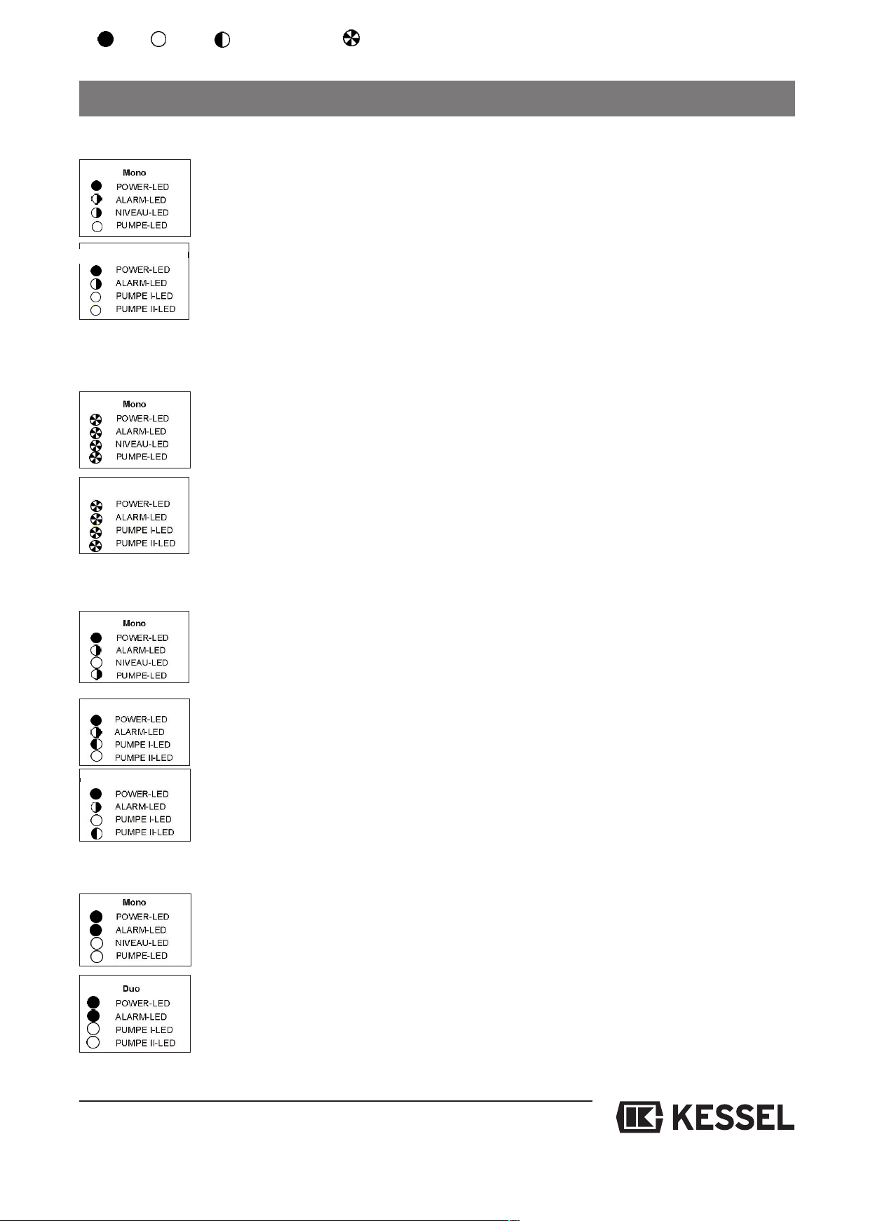
Sensor fault
Duo Pump 1/2
8. Malfunctions and troubleshooting
- Drop in pressure:
Water level has fallen by 12 mm without the pump having been running
--> Pump the submersible pipe/plunger free by hand
-> Check the air hose for leaks
-
Rotary field / phase fault
Duo Pump 1/2
Relay switching cycles
Duo Pump 1
Duo Pump 1
- Rotary field fault:
Wrong rotary field for mains connection of switch unit
--> Swap 2 phases
- Phase fault:
Phase L1 or L2, L3 not available
--> Check connection on the switch unit, mains cable, fuses,
check fault-current circuit breaker
--> If L1 has failed, direction of rotary field cannot be recognised.
--> If L1 has failed, the switch unit goes into battery-operated mode
Power contactor has exceeded 100,000 switching cycles
--> Can be acknowledged, power contactor makes another 1,000 switching cycles
before the message is repeated
--> Replace contactor --> Contact Customer Services
--> The fault "relay switching cycles" is recurring
Alarm level exceeded
Alarm level is reached by water level
--> Alarm goes out automatically when the level drops below the alarm level again
--> LED only goes out after manual acknowledgement has taken place
--> Check inlet
--> Check level measurement and switching points
25
Page 26
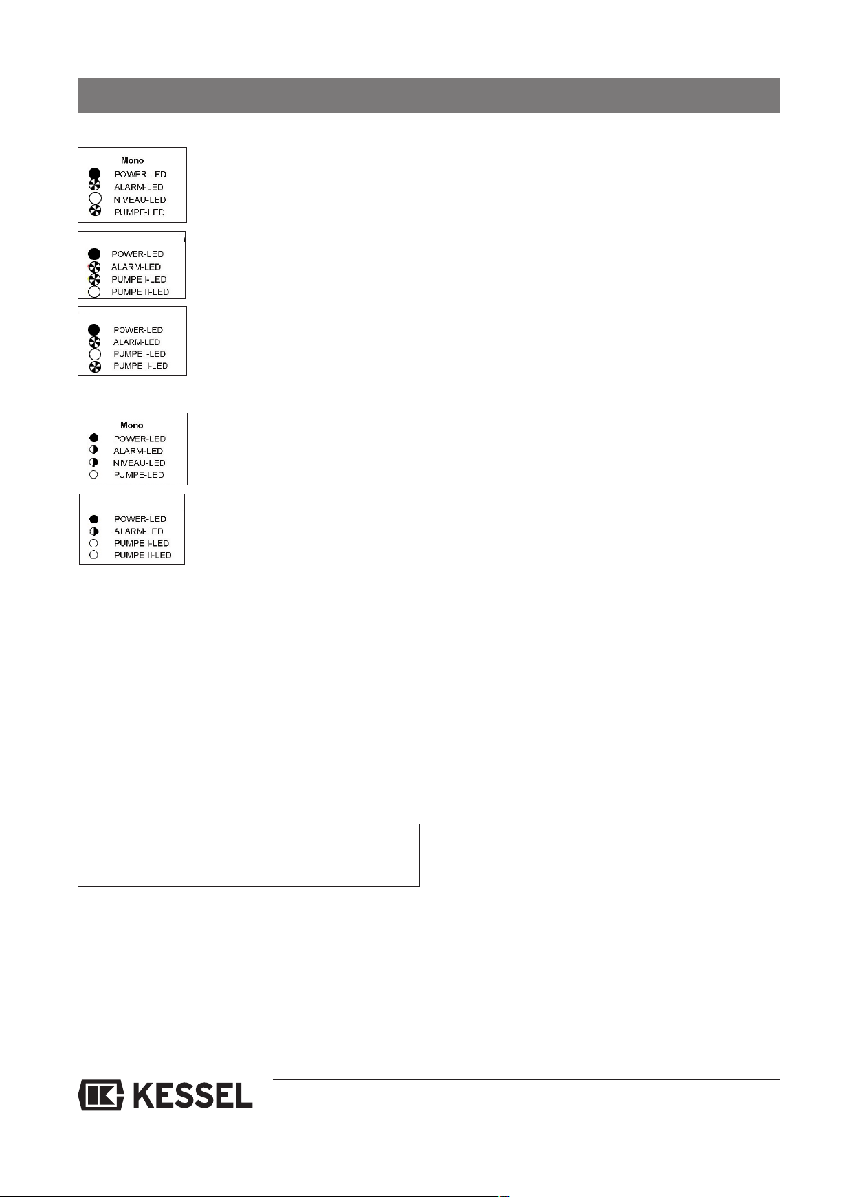
Relay fault
Duo Pump 1
Duo Pump 2
Level fault
Duo Pump 1/2
8. Malfunctions and troubleshooting
ower contactor no longer switches off
P
--> Disconnect switch unit from the mains
--> Replace contactor --> Contact Customer Services
Level fault (only with pressure diaphragm switch): Control cable to the switch unit is not
laid on a continual gradient
--> Check cable route, shorten any excess lengths if appropriate.
The switches ON and ALARM switch in the wrong order
--> Pressure control unit faulty, replacement necessary
8.2.1 Irregular level states (up to 12/09)
Malfunctions of level switches can be recognised in part and
trigger a meaningful emergency control in "automatic" operating mode. If the control unit recognises an implausible
level switch state, the malfunction message "level" is indicated by the red "running time/level" LED flashing and the
"malfunction" relay. The malfunction message can be deleted using the "alarm reset" key when the fault has been remedied or when no level fault can be detected on account of
pending level signals. Generally speaking it is not possible
to distinguish between non-closing "alarm" level switches
and non-opening "on" level switches.
Irregular level states usually indicate a fault in the level
switches or wiring. Maintenance may only be carried out
by a qualified electrician.
a) Single system
No distinction can be made between a non-closing "on" level
switch and a non-opening "alarm" level switch. If "alarm"
level is pending without "on" level, a level fault is indicated.
The motor is not switched on. If the "on" level switch closes
in this state, however, the pump is switched on. Opening the
"on" level switch switches the pump off.
b) Twin system
• Non-closing "on 1" level switch
Malfunction message follows the "on 2" level being exceeded. If the "alarm" level is exceeded, both pumps switch on.
If the level drops below the "on 2" level, the pumps switch off.
• Non-closing "on 2" level switch
Malfunction message follows the "alarm" level being exceeded. At the same time, the second pump is switched on. Both
pumps remain in operation until the level falls below "on 1"
again.
• Permanently closed "on 2" level switch
Malfunction message follows the "on 1" level not being reached. One pump switches on when the "on 1" level is exceeded, the second pump when the "alarm" level is exceeded.
• Permanently closed "alarm" level switch
Malfunction message follows when "alarm" level is indicated
but at least "on 2" level is not reached. A permanent "alarm"
message is then sent. The alarm message via the internal
signal sensor can be deleted by actuating the "alarm reset"
key. The "alarm" relay remains active, however, until the fault
has been eliminated. One pump is switched on when the "on
1" level is exceeded, the second pump when the "on 2" level
is exceeded. Both pumps are switched off after the level falls
below "on 1".
26
Page 27

.2.2 Internal monitoring
8
8. Malfunctions and troubleshooting
The control unit evaluates the signals of the phase/rotary field
monitoring, motor protection switch and motor temperature
ensor regardless of the configuration. In the event of a mal-
s
function or non-readiness for operation, the pump is switched
ff or the switch-on suppressed. In addition, a fault is indica-
o
ted by the respective display LED and the malfunction relay
switching.
hase/rotary field monitoring
P
If L2 and/or L3 fail, the "phase/rotary field" LED is permanently lit, and the "malfunction" relay becomes active. (In this
case the control unit can no longer recognise rotary field
faults.) Since the control unit is supplied by L1, failure of L1
cannot be indicated. If L1 fails, however, the built-in signal
sensor is switched on provided the rechargeable battery is
inserted in the control unit and charged.
In the case of false rotary field (anti-clockwise rotary field) the
"phase/rotary field" LED flashes. The contactor for the motor
output is disabled by the control unit.
Motor protection switch
One auxiliary contact (each) of the motor protection switch is
evaluated. If a motor protection switch has triggered on account of manual actuation, short-circuit or exceed load, a
malfunction is indicated by the "motor protection switch" LED
(or LED "pump ... MSS/temp" is permanently lit) and the
"malfunction" relay. In addition, the contactor for the motor
output is disabled by the control unit.
or on twin systems with
– Phase/rotary field
Pump 2 MSS/temp
–
– Pump 1 MSS/temp
Running time/level
–
The conditions for the malfunction messages are described
in detail in the previous chapters.
.2.4 "Alarm" message
8
Alarm messages are sent through:
• Activation of the "alarm" relay and thus through the war-
ning device connected to this.
• The internal signal sensor
Two conditions can lead to an alarm message.
1. An alarm message is issued if the level exceeds the
"alarm" level. The internal acoustic alarm can be switched
off again by pressing the "alarm reset" key. As soon as the
level falls below the "alarm" level, both alarm messages
(signal sensor and relay) are reset.
2. If a replaceable battery (battery) is inserted and charged,
an alarm message is also issued if there is a power failure, i.e. the mains power failure is indicated by an acoustic
signal triggered by the internal signal sensor. The rechargeable battery supplies the internal signal sensor for a few
hours depending on the charge state. The internal acoustic alarm can be switched off again by pressing the "alarm
reset" key.
Motor temperature
In every motor, there is a temperature sensor which indicates excess temperature to the control unit:
When excess temperature has been reached (approx. 110
°C) this is indicated (flashing) by the "motor temperature"
LED (or "pump ... MSS/temp" LED in the case of a twin system) and the "malfunction" relay drops out. In addition, the
contactor for the respective motor output is disabled by the
control unit. When the motor has cooled down again, the
pump is automatically ready for operation as soon as the
temperature sensor indicates this.
8.2.3 "Malfunction" message
SMalfunction messages are sent through:
• Activation of the "malfunction" relay and thus through the
warning device connected to this.
• Display of the type of malfunction by the malfunction LEDs
on individual systems with
– Phase/rotary field
– Motor protection switch
– Motor temperature
– Running time/level
8.2.5 What to do when...
... the motor protection switch has triggered.
Remove the transparent housing cover (heed instructions!) and press the black "START" switch on the motor protection switch. If the motor protection switch triggers again,
please contact a qualified electrician.
... another malfunction message occurs.
If the malfunction cannot be eliminated within the context of the operating instructions, please contact a qualified
electrician.
... the control unit no longer reacts to input signals, but signalises readiness for operation through the "operation" display.
Disconnect the control unit completely from the mains
for about 10 seconds using the mains switch on the installation side. If the control unit still does not work, please contact
a qualified electrician.
27
Page 28
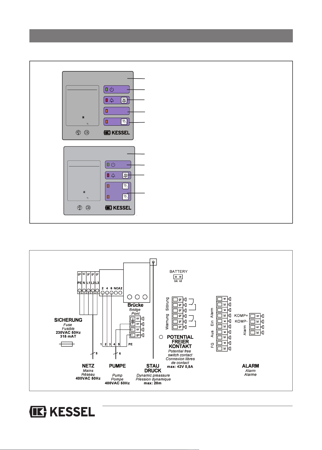
Aqualift F Mono 400V
N
IVEAU
L
EVEL
PUMPE
P
UMP
K
urzbedienungsanleitung:
Netzverbindung herstellen
grüne Netzanzeige
Automatikbetrieb
Niveau-Anzeige leuchtet
Pumpniveau erreicht
Pumpen-Anzeige leuchtet
Pumpe läuft
U
nterdrücken des
akustischen
A
larms mit - Taste
A
usschalten/Handbetätigen
der Pumpe mit - Taste
g
g
g
g
134,8 mm
R 3 -0,2mm
Pumpe I
Pump I
Pumpe II
Pump II
Aqualift F Duo 400V
Kurzbedienungsanleitung:
N
etzverbindung herstellen
grüne Netzanzeige
Automatikbetrieb
Pumpe I läuft
Pumpe II läuft
U
nterdrücken des
akustischen
Alarms mit - Taste
Ausschalten/Handbetätigen
der Pumpe mit - Taste
Pumpe I-Anzeige leuchtet
P
umpe II-Anzeige leuchtet
g
g
g
g
134,8
mm
R3-0,2mm
.1 Switch unit (from model year 01/10)
9
9. Control unit
Display/indicator panel
Pilot lamp indicating readiness for operation
c Pilot lamp for alarm message (the activated
alarm can be switched off by acknowledging
the alarm key)
Pump can be switched on manually by
pressing this twice
e Switch-on level reached
(pump automatically starts up once
switch-on delay has expired)
9.1.1 Circuit diagram single system (from model year 01/10)
28
Page 29
9. Control unit
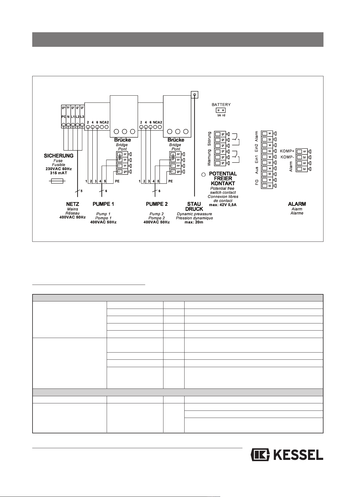
9.1.2 Circuit diagram twin system (from model year 01/10)
9.2 Switch unit (up to model year 12/09)
9.2.1 Switch unit for single system (up to model year 12/09)
Description of the display and control elements
Display elements (LED’s)
Normal mode Operation
(for information Level „Alarm“ yellow "Alarm" level reached
for the operator) Level „On“ yellow On" level reached
Level „Off“ yellow no function
Pump yellow Pump output activated
Malfunction
(for information for the Flashing: Rotary field fault
fitter, motor protection Motor protection switch red Motor protection switch has triggered
switch also for the operator) Motor temperature red Flashing: "Temperature A" (TF)
Control elements
Manual - 0 - Auto
Alarm Reset
Motor protection switch
Phase/rotary field red Permanently lit: Phase failure (has display priority)
Running time / Level red Permanently lit: Running time fault
Sliding switch Choice of operating mode
Key Reset / alarm signal sensor test
Switch Triggered when pump has excess current
yellow
Voltage supply OK
Flashing: Level fault
saving - priority treatment
Reset of a level fault display
Reset of excess motor temperature
29
Page 30
9. Control unit
• The operating elements can be accessed once the transarent housing cover has been removed. The housing
p
cover may be removed for operational purposes, but it only
makes sense for service work.
• The protective rating given is reduced when the cover is
removed (water-tightness). Before removal, it must be
checked whether there is a hazard through high humidity
r splashwater. In this case, the control unit must be swit-
o
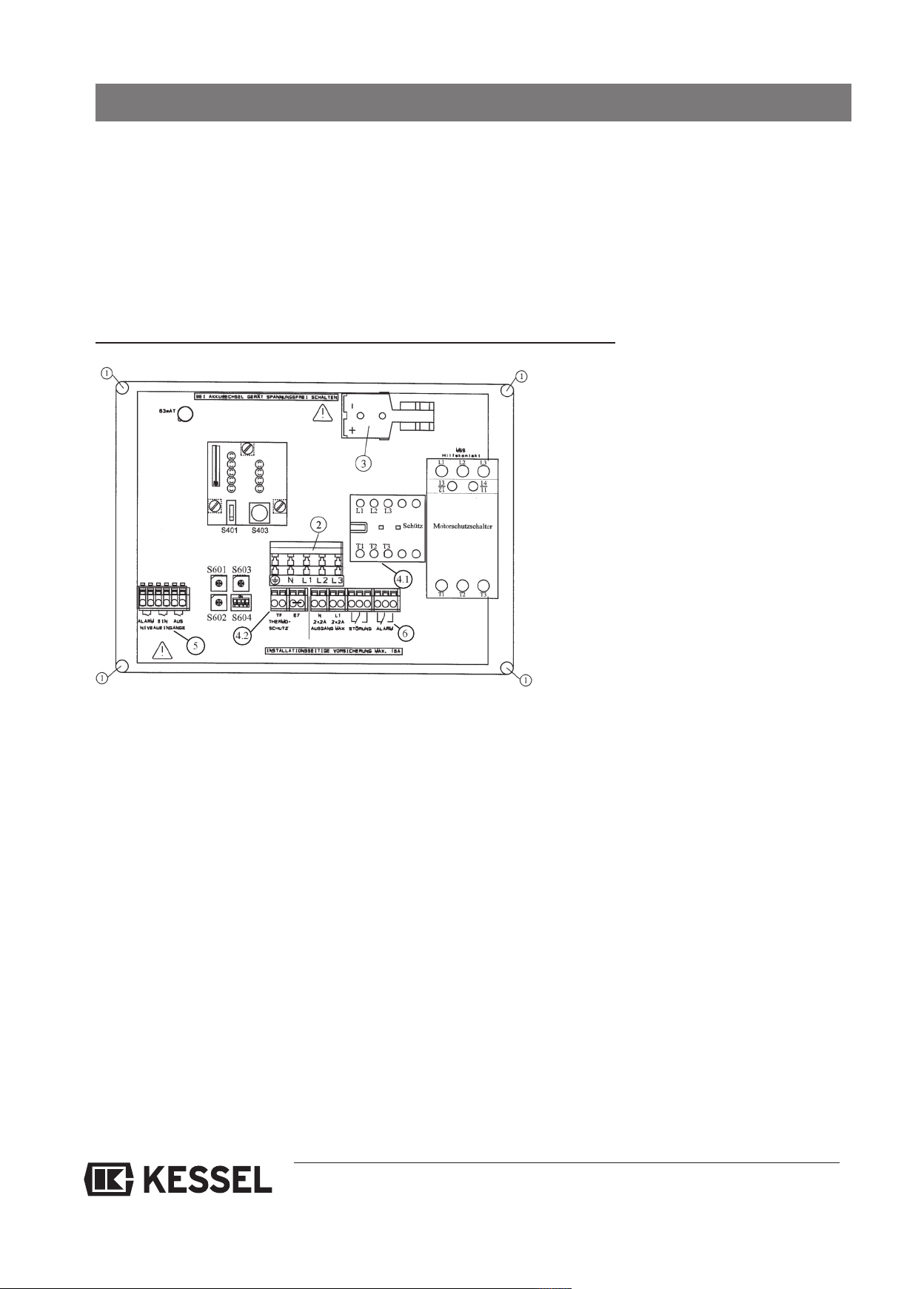
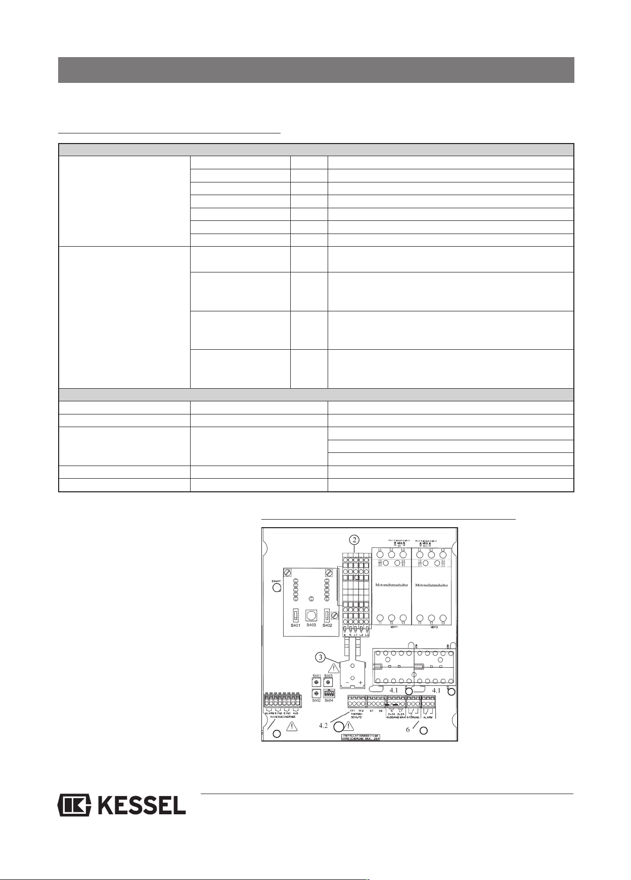
View of the inside of the switch unit (schematic, not to scale) up to model year 12/09
ched voltage-free first. In case of doubt, a qualified elec-
rician must always be consulted.
t
• The current set at the motor protection switch must correspond with the rated current of the connected motor and
must not be adjusted by the operator.
• Following operation, the housing cover must be sealed
properly again to guarantee the
1. Holes for on-site M6 screws for wall
2. Mains supply
3. Slot for rechargeable battery (rechar-
4.1 Connection of supply for pump motor
4.2 Connection of temperature monitoring
5. Connection for level inputs
attachment
geable battery available as accessory)
for pump motor
6. Connection for external malfunction
and alarm message
30
Page 31
9. Control unit
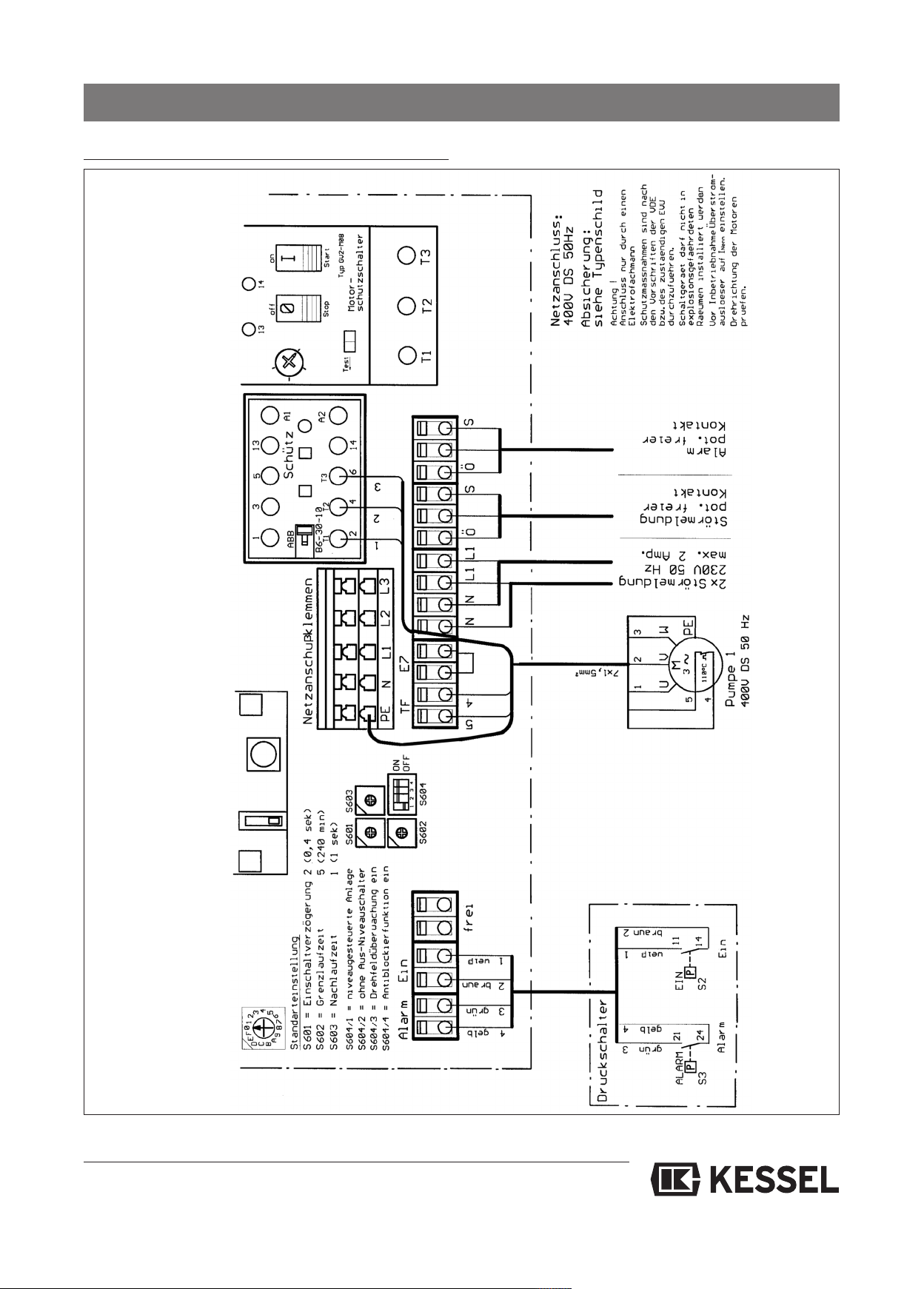
.2.2 Switch unit for single system (from model year 12/09)
9
Edition 04.99 / Du / EINZ-F
31
Page 32
9. Control unit
.3 Switch unit for double system (up to model year 12/09)
9
.3.1 Description of the display and control elements
9
Display elements (LEDs)
Normal mode
(for information for the user Level „Alarm“ yellow "Alarm" level reached
Malfunction
(for information for the Flashing: Rotary field fault
fitter, motor protection switch Pump 2 MSS/Temp red Permanently lit: Motor protection switch
also for the operator) hat ausgelöst
Bedienelemente
Manual - 0 - Auto (Pump 1)
Manual - 0 - Auto (Pump 2)
Alarm Reset
Motor protection 1
Motor protection 2
Operation green Voltage supply OK
evel „On2“ yellow "On 2" level reached
L
Level „On1“ yellow "On 1" level reached
evel „Off“ yellow no function
L
Pump 1 green Pump output 1 activated
Pump 2 green Pump output 2 activated
Phase / rotary field red Permanently lit: Phase failure (has display priority)
Flashing: Excessive motor temperature Pump 2
Pump 1 MSS/Temp red Permanently lit: Motor protection switch pump 1
has triggered
Flashing: Excessive motor temperature pump 1
Running time/level red Permanently lit: Running time fault
Flashing: Level fault
saving - priority treatment
Sliding switch Choice of operating mode for pump 1
Sliding switch Choice of operating mode for pump 2
Key Reset / alarm signal sensor test
Reset of a level fault display
Reset of excess motor temperature
Switch Triggered when pump 1 has excess current
Switch Triggered when pump 2 has excess current
• The operating elements can be accessed
once the transparent housing cover has
been removed. The housing cover may be
removed for operational purposes, but it
only makes sense for service work.
• The protective rating given is reduced
when the cover is removed (water-tightness). Before removal, it must be checked
whether there is a hazard through high
humidity or splashwater. In this case, the
control unit must be switched voltage-free
first. In case of doubt, a qualified electrician must be consulted.
• The current set at the motor protection
switch must correspond with the rated current of the connected motor and must not
be adjusted by the operator.
• Following operation, the housing cover
must be sealed properly again to guarantee the protective rating (water-tightness).
View of the inside of the switch unit (schematic, not to scale)
1. -
2. Mains supply
3. Slot for rechargeable battery (rechargeable battery
available as accessory)
4.1 Connection of supply for
pump motor
4.2 Connection of temperature
monitoring for pump motor
5. Connection of level inputs
6. Connection for external
malfunction and alarm mes-
4.1
4.1
sage
32
Page 33
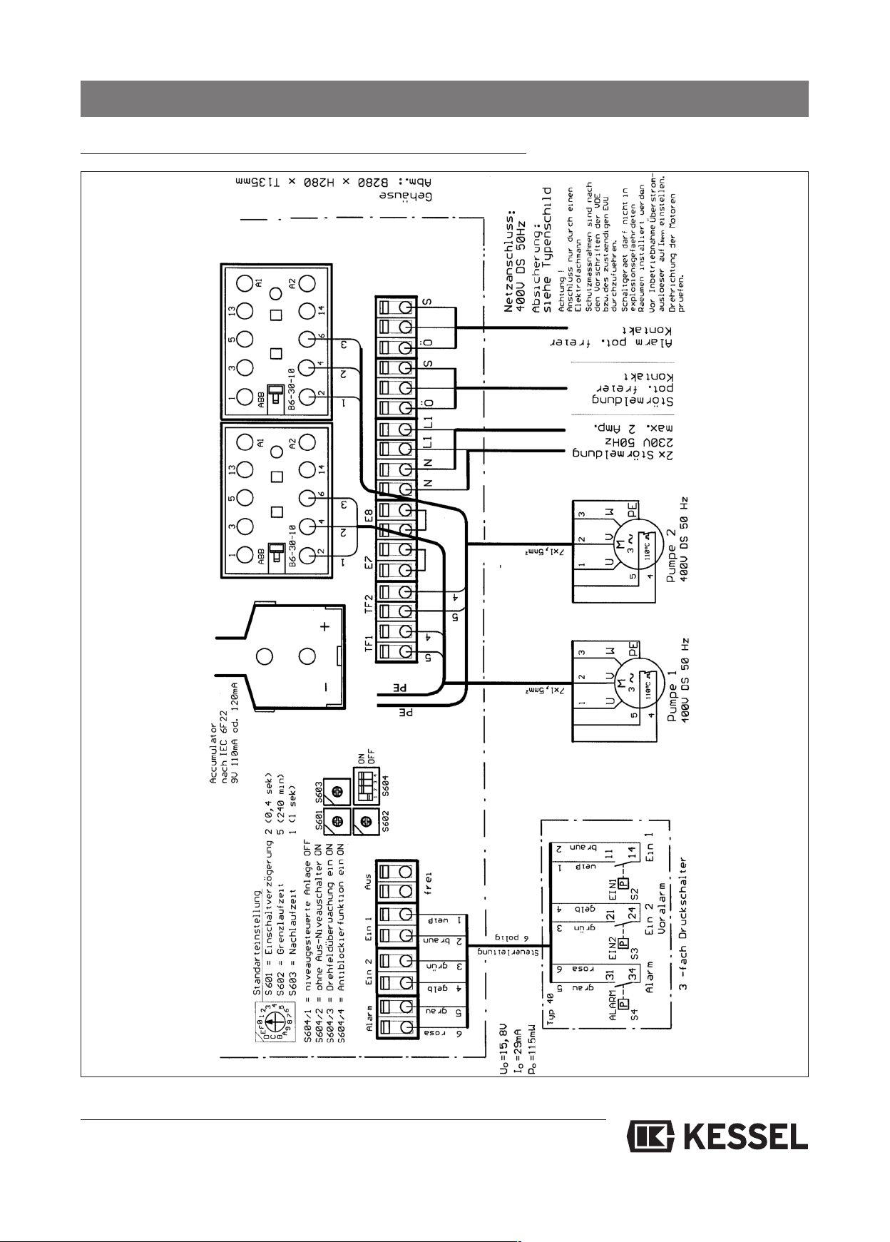
9. Control unit
.3.2 Switch unit for double system (Aqualift Duo) (up to model year 12/09)
9
Edition 04.99 / Du / DUO-F
33
Page 34
10. Spare parts and accessories
0.1 Accessory parts
1
Designation Article-Nr.
Manual diaphragm pump 28680
Shut-off valve for manual diaphragm pump 28681
Elastic hose connection
with 2 hose clamps DN 40 28660
N 70 28661
D
DN 100 28663
Flange-hose connection DN 80 28655
DN 150 28658
Plastic shut-off valve for pressureless installation DN 100 28698
DN 150 28699
Sound insulation (underlay mat) Single system 28692
Twin system 28693
Seal for pipe duct DN 50 850114
DN 70 850116
DN 100 850117
DN 125 850118
DN 150 850119
Saw cap DN 50 - DN 150 50100
Battery (1 unit) from model year 01/2010 197-081
Rechargeable battery up to model year 12/2009 20230
Non-return valve for mono systems DN 100 28683
Non-return valve for duo systems DN 100 28694
Compressor set for bubble formation
for greater operational safety with grease discharge and hygiene articles 28048
Air filter for compressor motor protection (28048) 363-140
Motor protection switch 2,5 -4 Amp. 363-134
Motor protection switch r 4-6,3 Amp. 363-135
Motor protection switch 6,3-10 Amp. 363-136
Contactor 363-151
Refer to Kessel catalogue
34
Page 35
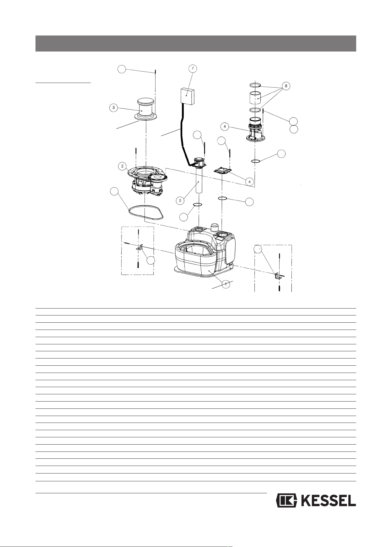
0.2 Spare parts
1
0.2.1 Single system
1
10. Spare parts and accessories
14
10
15
15
12
11
16
7
1
13
9
9
Position Units Part no. Description
11206-004 Mono tank
21206-161 Pump flange complete (F)
3a 1 367-002 Motor complete 1.1 kW / 400 V
3b 1 367-003 Motor complete 2.2 kW / 400 V
41240-051 Mono flap housing DN 100
5a (up to 12/09) 1 206-017 Mono pressure control unit complete
5b (up to 01/10) 1 206-208 Mono submersible pipe
61206-018 Cleaning cover
7a (up to 12/09) 1 206-048 Mono switch unit 1,1 kW
7a (up to 12/09) 1 206-116 Mono switch unit 2,2 kW
7b (up to 01/10) 1 363-100 Mono switch unit 1,1 kW
7b (up to 01/10) 1 363-101 Mono switch unit 2,2 kW
8128663 Elastic hose connection DN 100
92206-054 BG attachment bracket
10 1 206-042 Profile seal
11 1 049-010 Lip seal
12 1 049-011 Lip seal
13 1 049-005 Rolling ring
14 4 017-095 Cylinder head screw
15 8 206-074 PT screw
16 8 017-199 Cylinder head screw M8x25
17 8 017-012 Washer
18 1 367-007 Seal
19 1 206-228 PE-hose 6 x 4 mm (5m)
19 1 206-227 PE-hoses 6 x 4 mm (10m)
35
Page 36
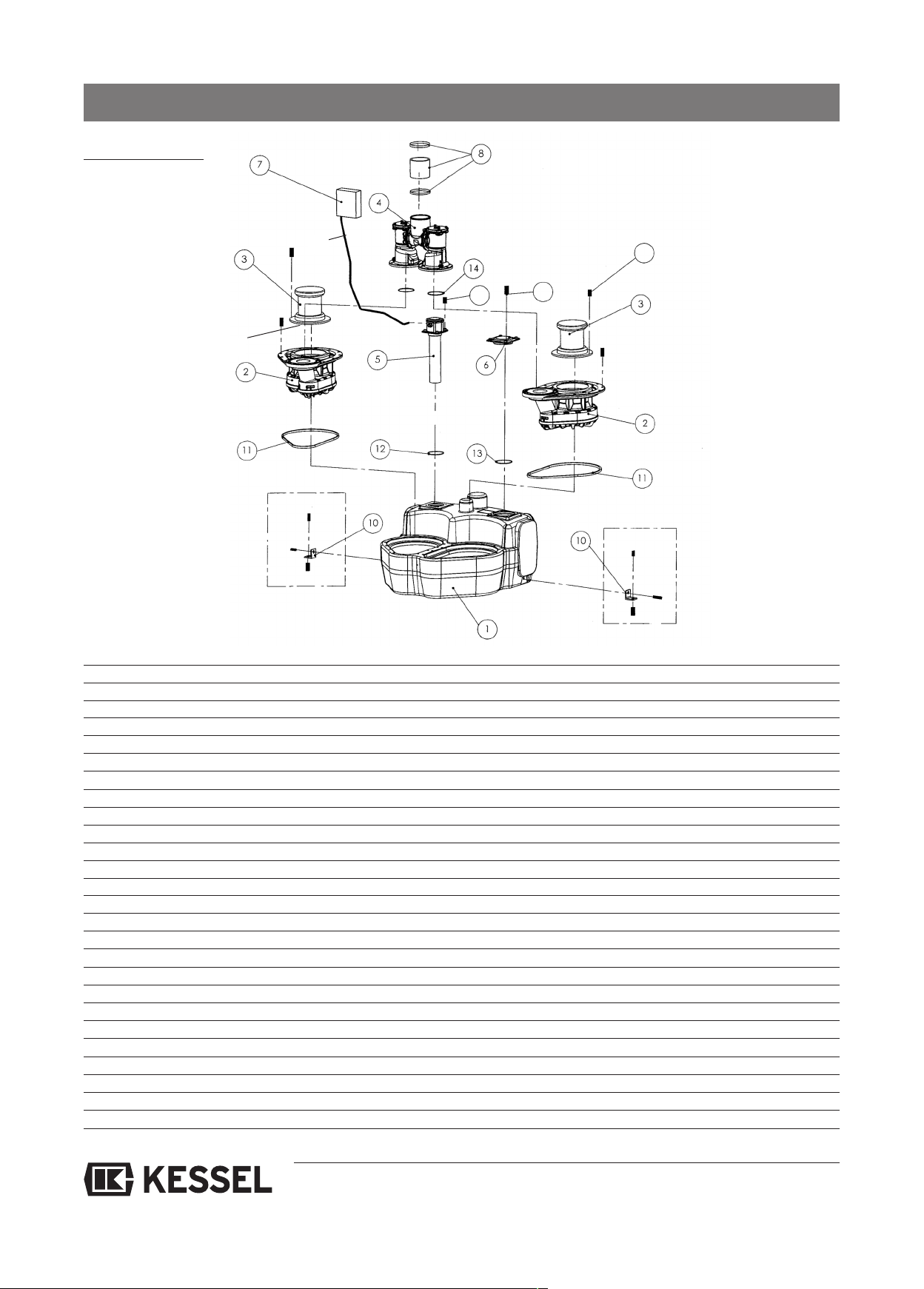
10.2.2 Twin system
10. Spare parts and accessories
22
15
20
2
6
1
1
Position Units Part no. Description
11206-005 Duo tank
22206-161 Pump flange complete (F)
3a 2 367-002 Motor complete t 1,1 kW / 400 V
3b 2 367-003 Motor complete 2,2 kW / 400 V
41240-056 Duo return flow lock complete DN 100
5a (up to 12/09) 1 206-022 Duo pressure control unit complete
5b (from 01/10) 1 206-224 Duo submersible pipe (from model year 01/10)
61206-018 Cleaning cover
7a (up to 12/09)1 206-049 Duo switch unit 1.1 kW 400 V
7a (up to 12/09)1 206-117 Duo switch unit 2.2 kW 400 V
7b (from 01/10) 1 363-117 Duo switch unit 1.1 kW 400 V
7b (from 01/10) 1 363-118 Duo switch unit 2.2 kW 400 V
8128663 Pressure hose D = 110 x 6 for DN 100
92003-144 Pipe clamp D = 120 for DN 100
10 2 206-054 BG attachment bracket
11 2 206-042 Profile seal
12 1 049-010 Lip seal
13 1 049-011 Lip seal
14 2 049-005 Rolling ring
15 8 017-095 Cylinder head screw
16 4 206-074 PT screw
17 14 017-199 Cylinder head screw M8x25
18 14 017-012 Washer
20 4 017-213 Lens head screw M6
21 1 367-007 Seal
22 1 206-228 PE hose 6 x 4 mm (5m)
22 1 206-227 PE hose 6 x 4 mm (10m)
36
Page 37
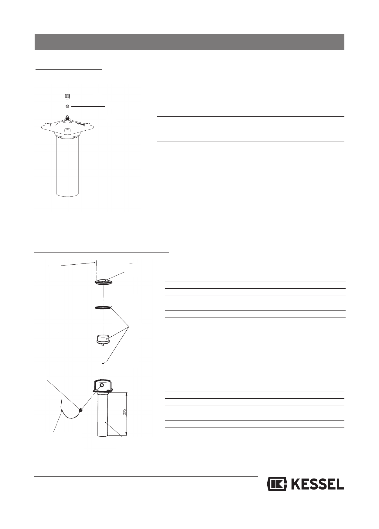
10. Spare parts and accessories
0.2.3 Submersible pipe L = 175 mm
1
➂
➁
➀
Single system (206-208)
Double system (206-224)
Pos. Unit Part-No. Description
11 197-333 Bulkhead fitting
21 197-340 Clamping ring for bulkhead fitting
31 197-339 Closing nut for bulkhead fitting
1 206-228 PE hose 6 x 4 mm (5m)
1 206-227 PE hose 6 x 4 mm (10m)
10.2.4 Pressure control unit (up to model year 01/10)
➄
➁
➀
➂
Single system (206-017)
Pos. Unit Part-No. Description
11 28045 Pressure control unit mono
21 206-014 Upper part of pressure control unit
31 206-045 Cable screw connection
4 5m 206-047 Cable
52 017-153 PT screw
Double system (206-022)
Pos. Unit Part-No. Description
11 28046 Pressure control unit duo
21 206-014 Upper part of pressure control unit
31 206-045 Cable screw connection
4 5m 206-047 Cable
52 017-153 PT screw
➃
37
Page 38

10. Spare parts and accessories
10.2.5 Mono flap housing DN 100 (part no. 240-051)
➂
➄
➃
➀
➁
Pos. Unit Part-No. Description
11 240-046 Flap housing
21 240-048 Hose connection 110
1 240-038 Hex. locknut M8
3
1 240-037 O-Ring
4
5a 1 240-068 Backwater flap for 1,1 kW
inc. flap stay
5b 1 240-069 Backwater flap for 2.2 kW
inc. flap stay
38
Page 39
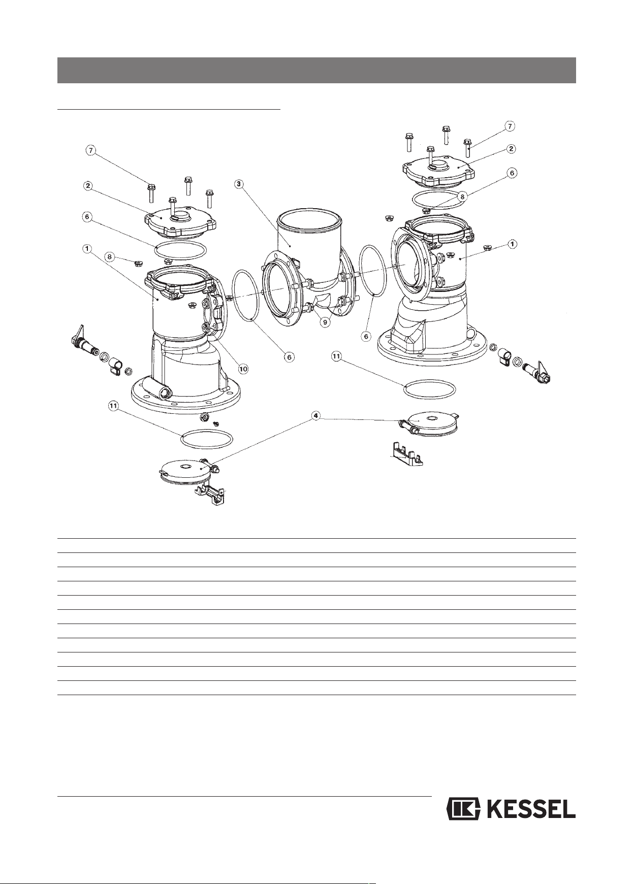
10. Spare parts and accessories
0.2.7 Mono flap housing DN 100 (part no. 240-056)
1
Pos. Units Part no. Description
12240-007 Duo RS housing
22240-045 Pressure cover closed
31240-009 T-piece DN 100
4a 2 240-068 Backwater flap for 1.1 kW inc. flap stay
4b 2 240-069 Backwater flap for 2.2 kW inc. flap stay
64240-027 O-Ring
78240-058 Hexagon safety screw M6
88240-059 Hexagon safety screw M6
98240-038 Hexagon safety screw M8
10 8 240-039 Hexagon safety screw M8
11 2 049-005 Rolling ring DN 125
39
Page 40

11. Warranty
1. In the case that a KESSEL product is defective, KESSEL has
the option of repairing or replacing the product. If the product
remains defective after the second attempt to repair or replace the product or it is economically unfeasible to repair or replace the product, the customer has the right to cancel the
order / contract or reduce payment accordingly. KESSEL
must be notified immediately in writing of defects in a product.
In the case that the defect is not visible or difficult to detect,
ESSEL must be notified immediately in writing of the defect
K
as soon as it is discovered. If the product is repaired or replaced, the newly repaired or replaced product shall receive
a new warranty identical to that which the original (defective)
product was granted. The term defective product refers only
to the product or part needing repair or replacement and not
necessarily to the entire product or unit. KESSEL products are
warranted for a period of 24 month. This warranty period be-
ins on the day the product is shipped form KESSEL to its cu-
g
stomer. The warranty only applies to newly manufactured
products. Additional information can be found in section 377
of the HGB.
In addition to the standard warranty, KESSEL offers an additional 20 year warranty on the polymer bodies of class I / II
fuel separators, grease separators, inspection chambers, wa-
stewater treatment systems and rainwater storage tanks. This
additional warranty applies to the watertightness, usability
and structural soundness of the product.
A requirement of this additional warranty is that the product is
properly installed and operated in accordance with the valid
installation and user's manual as well as the corresponding
norms / regulations.
. Wear and tear on a product will not be considered a defect.
2
Problems with products resulting from improper installation,
handling or maintenance will also be considered a defect.
Note: Only the manufacturer may open sealed components or
screw connections. Otherwise, the warranty may become null
and void
1.06.2010
0
40
Page 41
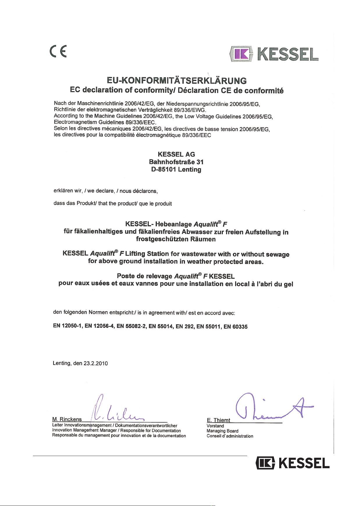
41
Page 42
Handover-Ceritficate
Handover certificate (copy for the company carrying out the installation)
❏ T
he initial operation and instruction was carried out in the presence of the person authorised to perform the
acceptance and the system operator.
❏ The system operator/person authorised to perform the acceptance was informed about the obligation to ser-
vice the product according to the enclosed operating instructions.
❏ Initial operation and instruction were not carried out.
The client/ person responsible for initial operation was handed the following components and/or product components
Initial operation and instruction is being carried out by (company, address, contact, phone)
The exact coordination of the dates for initial operation/instruction is being carried out by the system operator and person responsible for initial operation.
Place, date Signature of person Signature of system operator Signature of the company
authorised to perform acceptance carrying out the installation work
42
Page 43
Important contacts / Info
Separator Type: __________________________________________________________
Day / Hour __________________________________________________________
roject description / Building services
P
supervisor __________________________________________________________
Address __________________________________________________________
Telephone / Fax __________________________________________________________
Builder __________________________________________________________
Address __________________________________________________________
Telephone / Fax __________________________________________________________
Planner __________________________________________________________
Address __________________________________________________________
Telephone / Fax __________________________________________________________
Contracted plumbing company __________________________________________________________
Address __________________________________________________________
Telephone / Fax __________________________________________________________
Commissioning no. KESSEL
System operator / owner __________________________________________________________
Address __________________________________________________________
Telephone / Fax __________________________________________________________
Other remarks __________________________________________________________
__________________________________________________________
__________________________________________________________
__________________________________________________________
The system operator, and those responsible, were present during the commissioning of this system.
____________________________ ____________________________ ____________________________
Place and Date Signature Builder Unterschrift Anlagenbetreiber
Page 44
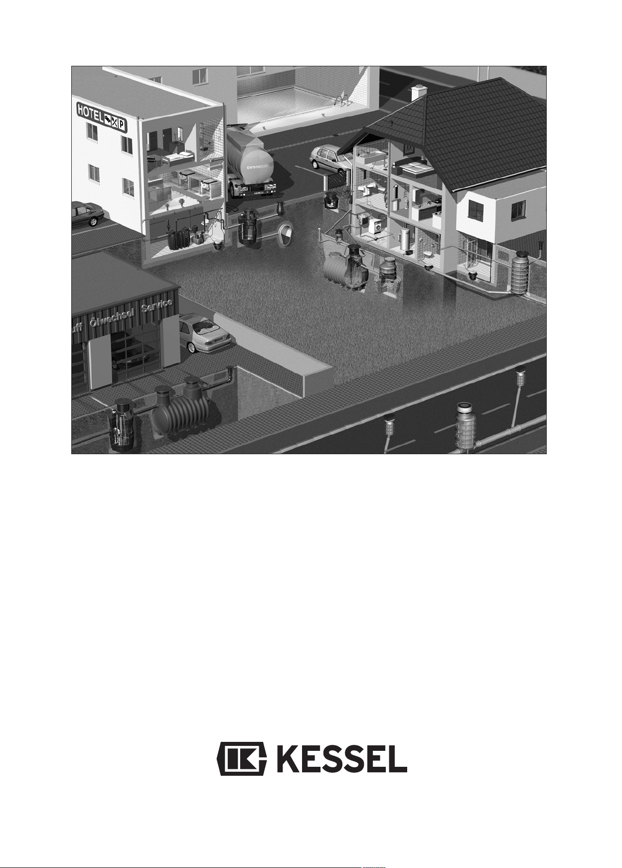
K
Backwater protection
K
Lifting Stations and pumps
K
Drains and shower channels
K
Separators
-Grease Separators
-Oil-/ Fuel-/Coalescence
Separators
-Starch Separators
-SedimentSeparators
K
Septic Systems
K
Inspection Chambers
K
Rainwater Management
Systems
 Loading...