

Page 1
INSTALLATION, OPERATING AND MAINTENANCE INSTRUCTIONS
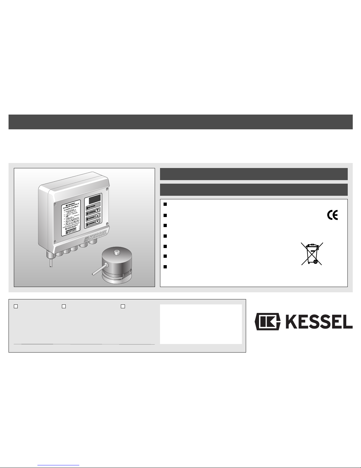
KESSEL Aqatronic®K switching device
for KESSEL
Aqabull
®
and
Aqadive
®
rainwater pumping systems
Includes ultrasonic probe (20m cable length)
Digital level indicator for the rainwater tank
Reprogrammable switching points
Floating contact
Visual / acoustic backwater alarm
High level of operating safety and reliability
Nationwide service network
Art. Nr. 85 030
Product advantages
Name/Signature Date Town/City
Specialist firm's stamp
Installation
on how to operate it are all provided by your local specialist
firm:
Putting into service
Instruction
Revision Status: 08/2010
Reference Number: 010-495
Design and specifications are subject to
change without notice
Page 2

2
Contents
1. General information
.............................................................................................................................. Page 3
2. Safety Instructions
.............................................................................................................................. Page 4
3. Technical Specifications
.............................................................................................................................. Page 5
4. System Description
.............................................................................................................................. Page 6
4.1 General system description.................................................................... Page 7
4.2
Aqabull
system description..................................................................... Page 8
4.3
Aqadive
system description.................................................................... Page 9
5. Installation
5.1 Switching device installation................................................................... Page 10
5.2 Ultrasound sensor installation ................................................................ Page 11
5.3 Installing the leakage probe.................................................................... Page 11
5.4 Levels and switching points in the tank .................................................. Page 12
6. Electrical Connection
.............................................................................................................................. Page 13
7. Commissioning
7.1 Initial start-up.......................................................................................... Page 15
7.2 Normal operation.................................................................................... Page 15
7.3 Manual drinking water top-up (TWvH).................................................... Page 15
7.4 Other functions ....................................................................................... Page 16
7.5 Default factory settings........................................................................... Page 17
7.6 Checking the set values ......................................................................... Page 20
7.7 Changing the set values......................................................................... Page 20
7.8 Master reset ........................................................................................... Page 21
8. Malfunctions and
8.1 Possible types of errors.......................................................................... Page 22
corrective action
8.2 Troubleshooting...................................................................................... Page 22
8.3 Simultaneous and Maintenance ............................................................. Page 23
9. Inspection and Maintenance
.............................................................................................................................. Page 24
10. Warranty
.............................................................................................................................. Page 25
11. Handover Certificate
.............................................................................................................................. Page 27
Page 3

3
1. General Information
Dear Customer,
Thank you for purchasing a KESSEL product.
The whole system was subjected to strict
quality control before leaving the factory.
Nevertheless, please check immediately
whether you have been delivered a complete, undamaged system. If you find any
transport damage, please follow the instruction in the "Warranty" chapter of this
document.
These installation, operating and maintenance instructions contain important information which must be noted and follow during installation, operation, maintenance
and repair of the system. The owner / operator and the responsible skilled personnel
must carefully read this document before
carrying out any work on the system and
must follow the instructions given.
KESSEL GmbH
Uses:
The Aqatronic K switching device is used to
control drinking water top-up and level monitoring for KESSEL Aqabull and Aqadive
rainwater pumping systems.
In normal operation the water level in the
tank is displayed. Various functions can be
controlled using the buttons. Delivery includes an ultrasound sensor with which the
water level in the tank is measured.
Page 4

2. Safety Instructions
The installation, operation, maintenance
and repair personnel must have the necessary qualifications for this work. The
owner/operator must clearly define responsibilities, accountability and monitoring of
the personnel.
Operating safety and reliability of the supplied system is only guaranteed for its proper intended use. The limit values given in
the technical specifications must never be
exceeded.
This system contains electrical voltages and
controls mechanical system parts. Failure to
follow the installation and operating instructions can result in substantial property damage, physical injuries or even fatal accidents.
The accident prevention regulations, relevant DIN and VDE standards and guidelines
as well as the regulations of the local power
supply company must be complied with during installation, operation, maintenance
and repair of the system.
The system is part of another, overall system. You must therefore also note and follow the operating instructions for the whole
system and the individual components.
Each time any installation, maintenance, inspection or repair work is carried out on one
of the components the whole system must
always be shut down and secured against
being switched back on again.
The system may not be operated in potentially explosive atmospheres.
The switching device is live and may not be
opened. Qualified electricians only may
carry out work on electrical equipment. The
term "qualified electrician" is defined in VDE
0105.
Ensure that the electrical cables and all
other electrical parts of the system are in
perfect working order. If any damage occurs, the system may not be started up and
must be repaired immediately.
The system has no effect on the quality of
the rainwater.
Modifications or changes to the system may
only be made in consultation with the manufacturer. Original spare parts and accessories approved by the manufacturer help to
ensure safety. Use of other parts can cancel liability for any resulting consequences.
4
Page 5

3. Technical Specifications
5
Voltage / frequency 230 VAC / 50 Hz
Power consumption of electronics 5W
Degree of protection / class IP54 / I
Temperature range 0 to 40 °C
Ultrasound sensor
Maximum measuring range / resolution 20 - 500 cm / 1 cm
Accuracy < 1% in relation to final value 500 cm dispersion angle 2a = 12° (sensitivity = 25)
Temperature range -10 to 40 °C
Degree of protection IP 67 / 5m for 10 min.; 1m for 24 hr.
Cable sheath diameter 6 mm
Cable sheath material PVC
Conductor cross-section 3 x 0.75 mm²
Cable length 20 metre
Changes to ultrasound sensor/cable to be made in consultation with KD only
Maximum cable length 80 metre, cable connection IP68 or better
Connection • Drinking water top-up 230VAC/ max. 450 W
• Output 1 = Rainwater filter rinsing 230VAC/ max. 450 W
• Output 2 = Operating safety 230VAC/ max. 450 W
• Floating contact 230 VAC / 2A; 10 - 30 V DC / 10 mA – 2 A;
without fusing and suppressor circuit for inductive loads
Electrical connections suitable for all copper conductors 0.08 - 2.5 mm2
Cable sheath diameter 5 - 9 mm
Leakage probe: a) Conductivity probe Conductivity range 10 - 1500µS / cm (for 3m cable length)
b) Optical probe Conductivity range unlimited
Dimensions • Housing L x W x H in mm 180x200x70
• Ultrasound probe Diameter x length in mm 85 x 80
Weight • Aqatronic K switching device 970 g
• Ultrasound probe without connection lead 260 g
Page 6
1
6
7
8
9
2
3
4
14 15 16 17
13
5
10
11
12
20
19
18
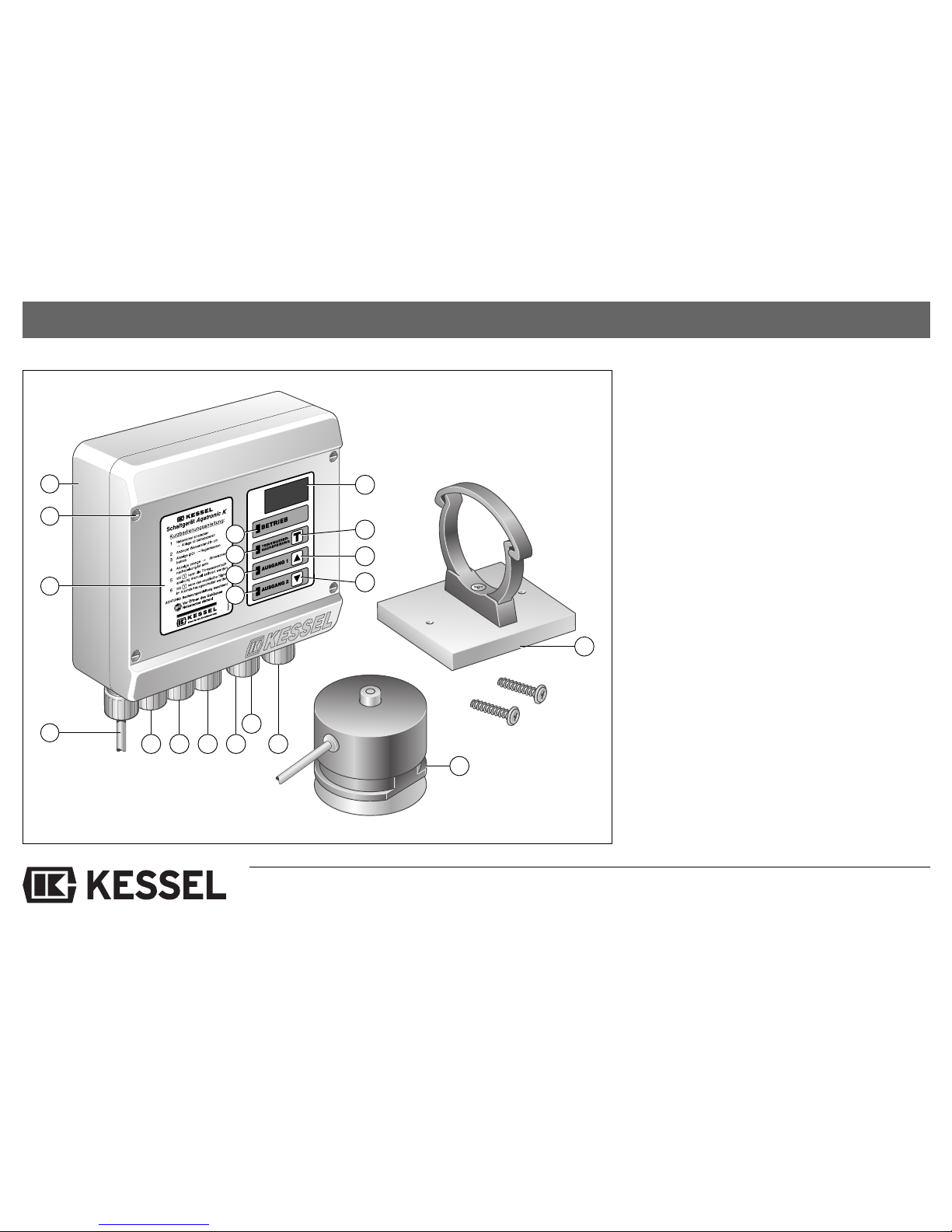
4. System Description
Switching device housing
Screw M4x28 (4x)
Power supply cord 1.5m
Quick reference guide
7 segment display, 3-digit
LED green display, normal operation
LED orange display, drinking water top-up
LED orange display, output 1 =
rainwater filter rinsing
LED orange display, output 2 =
operating safety
"T" button
Up "▲" button
Down "▼" button
Ultrasound sensor connection
Drinking water top-up connection
Rainwater filter rinsing connection
Operating safety connection
Floating contact connection
Leakage probe connection
Ultrasound sensor with 20m connection
lead
Mounting plate with accessories for fixing
the ultrasound sensor
6
Page 7

7
4. System Description
4.1 General system description
7 segment display, 3-digit (5)
In normal operation the current water level is
displayed in cm. The following are also displayed: Top-up time, error, set points and set
values.
LED green display, normal operation (6)
In normal operation the green LED is lit.
LED orange display, drinking water topup (7)
The orange LED is lit during drinking water
top-up.
LED orange display, output 1 = rainwater
filter rinsing (8)
The orange LED is lit if output 1 is activated.
LED orange display, output 2 = operating
safety (9)
The orange LED is lit if output 2 is activated.
"T" button (10)
The "T" button is used to manually switch on
drinking water top-up. In addition, the "T"
button is used to acknowledge errors, to
switch off the acoustic alarm, to select set
points and to save set values.
"
▲
▲
" button (11) and "
▼
▼
" button (12)
The two "▲" and "▼" buttons are used to select set points and set values.
Ultrasound sensor (19)
The ultrasound sensor measures the water
level in the tank.
The Aqatronic K switching device is used to
control drinking water top-up and level monitoring for KESSEL Aqabull and Aqadive
rainwater pumping systems.
The difference between the two systems is
the type of drinking water top-up and the location of the pump.
With the KESSEL Aqabull rainwater pumping system the water is topped up as and
when necessary via a separate top-up supply tank. The pump is located outside the
tank. With the KESSEL Aqadive rainwater
pumping system the top-up supply is fed directly into the tank. The pump is located inside the tank.
Note:
If the Aqatronic K switching device is
purchased without the rainwater pumping
system the switching device is in the Aqabull
basic setting.
Page 8
8
4. System Description
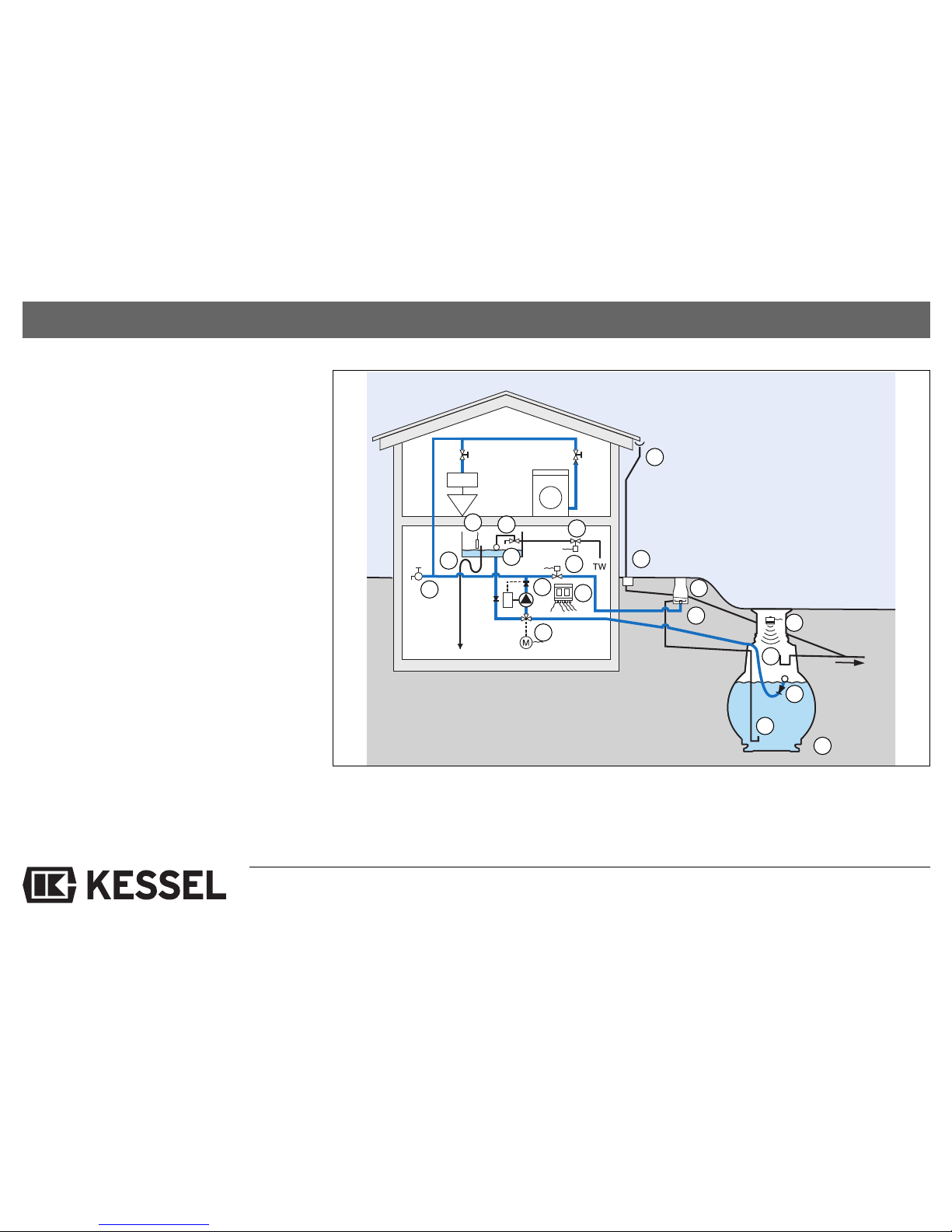
4.2 Aqabull system description
Gutter, downpipe
Rainwater drain with silt trap
Rainwater filter
Rainwater filter rinsing
Solenoid valve, rainwater filter rinsing
Tank
Inlet calming device
Overflow trap
Intake with float
Drinking water top-up supply tank
Float valve
Solenoid controlled emergency
mains supply
Emergency overflow with odour trap
Leakage probe
Pump with automatic pressure switch
3-way changeover valve,
drinking water top-up
Aqatronic K switching device
Ultrasound sensor
Non-potable water system
3a
3b
4a
4b
4c
5a
5b
6a
9a
1
5b
5a
5
6
7
8
9
10
2
3
3a
3b
4
4a
4b
9a
4c
6a
Page 9
4. System Description
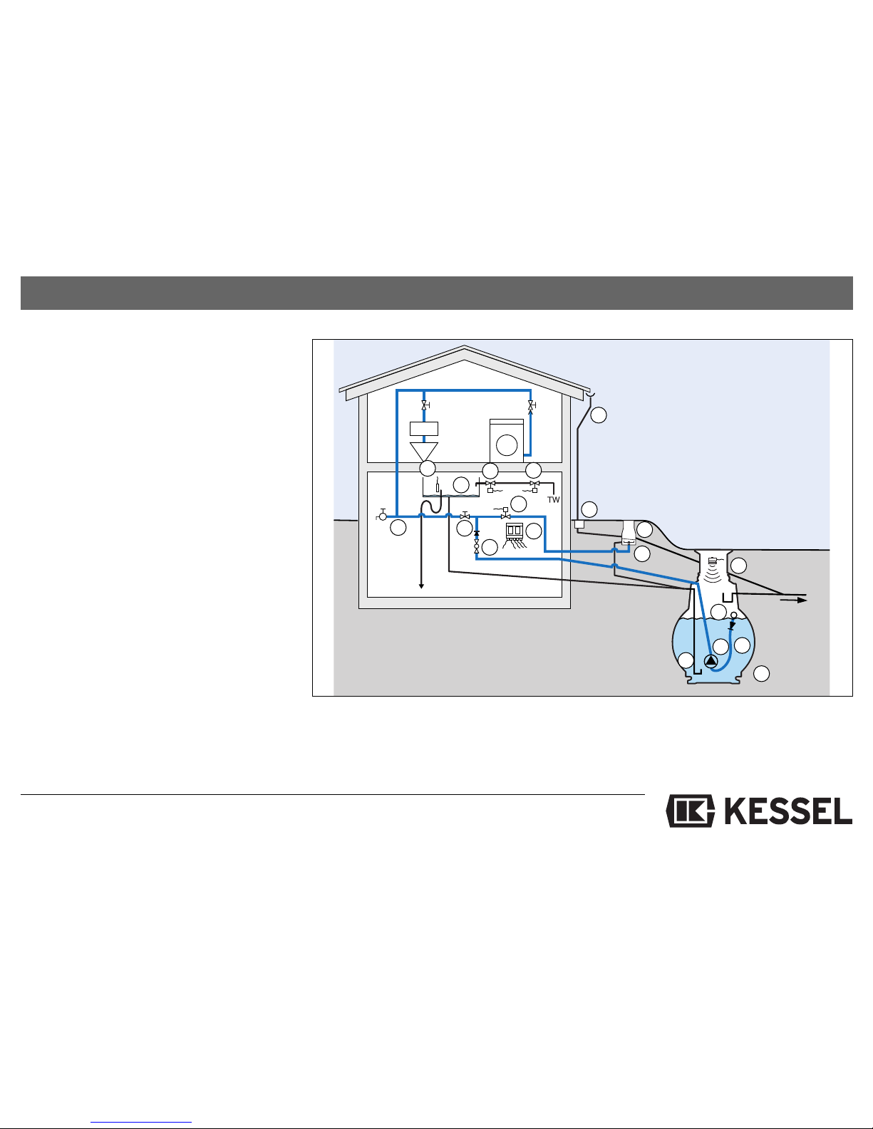
4.3 Aqadive system description
Gutter, downpipe
Rainwater drain with silt trap
Rainwater filter
Rainwater filter rinsing
Solenoid valve, rainwater filter rinsing
Tank
Inlet calming device
Overflow trap
Intake with filter
Pump
Automatic pressure switch
Service water system shut-off valve
Drinking water top-up
Solenoid valve, drinking water top-up
Solenoid valve, operating safety, drinking
water top-up
Leakage probe
Non-potable water system
A
qatronic K
switching device
Ultrasound sensor
3a
3b
4a
4b
4c
7b
7a
6a
7c
9a
9
1
2
4a
4b
4c
5
6
7
7a
6a
3b
7b
7c
8
9
9a
3
3a
4
Page 10
10
5. Installation
5.1 Switching device installation
Note and follow the Safety Instructions
chapter!
In a KESSEL Aqabull or Aqadive rainwater
pumping system the switching device is an
integral part of the system and is already
completely installed. If used separately, the
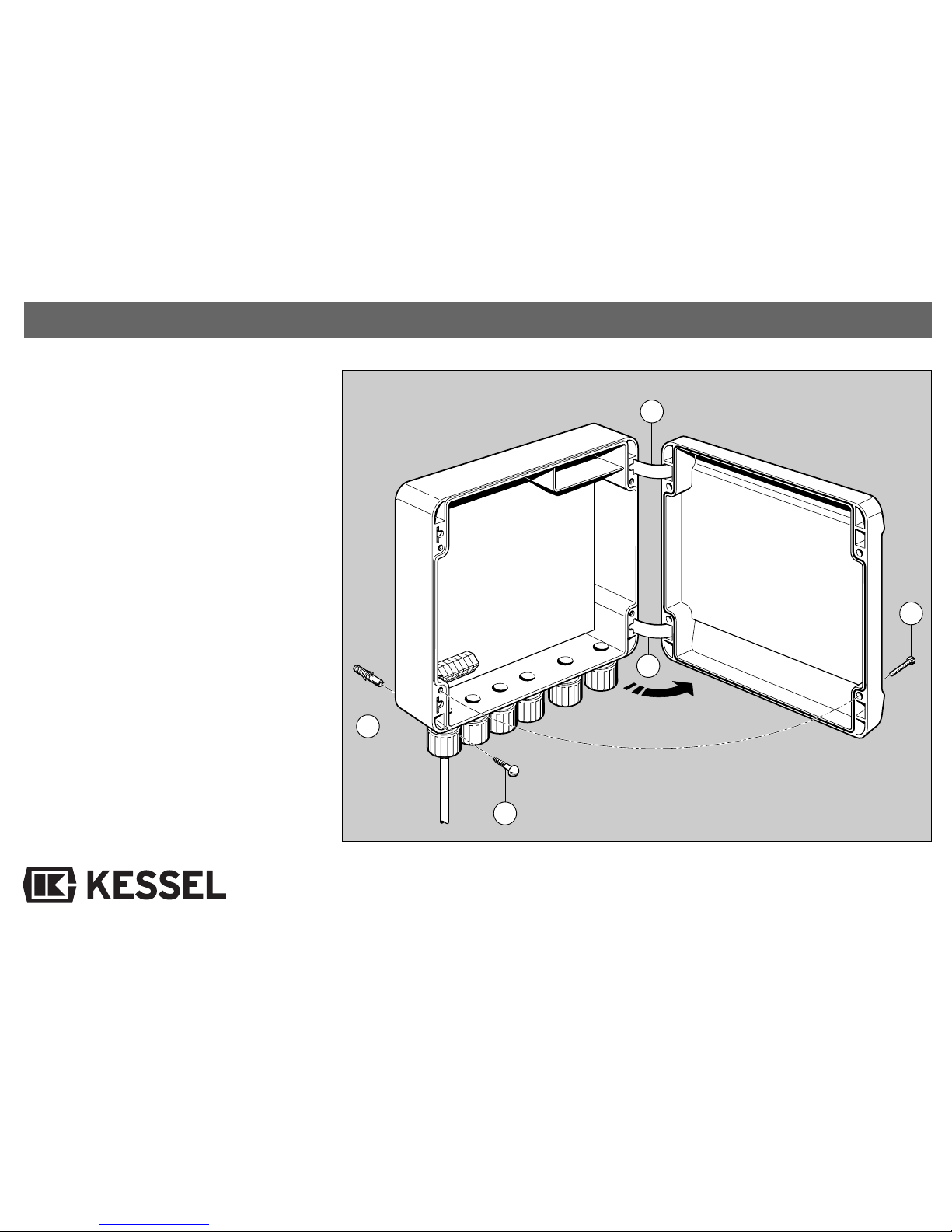
switching device is installed in a suitable position, e.g. mounted on the wall at eye level.
To do this, remove the four screws M4x25,
pull up the cover slightly and open up. Use
the 4 screws 3.5x30 to fix the control box to
the wall as illustrated. The screws as well as
plastic wall plugs and a drilling template are
included with the device.
Hinge (2x)
Plastic wall plug 5mm (4x)
Screw 3,5x30 (4x)
Cover screws (4x)
1
1
2
3
4
Schematic diagram of the switching device without electronic components.
Page 11
11
5. Installation
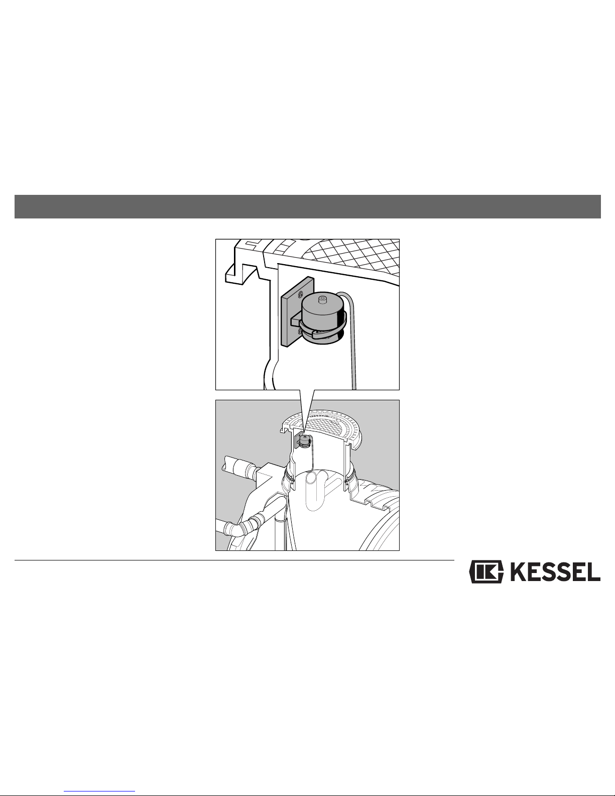
5.2 Ultrasound sensor installation
the following must be noted:
"Safety instructions" chapter
Handle the ultrasound sensor with care
Do not damage the sealing rubber between the attachment and tank
The ultrasound sensor must be aligned
perpendicular to the surface of the
water. The maximum deviation is 2°
Ensure there are no objects between the
ultrasound sensor and the surface of the
water (e.g. ball of the floating extractor)
The distance between the bottom edge
of the sensor housing and the highest
water level in the tank must be greater
than 20 cm
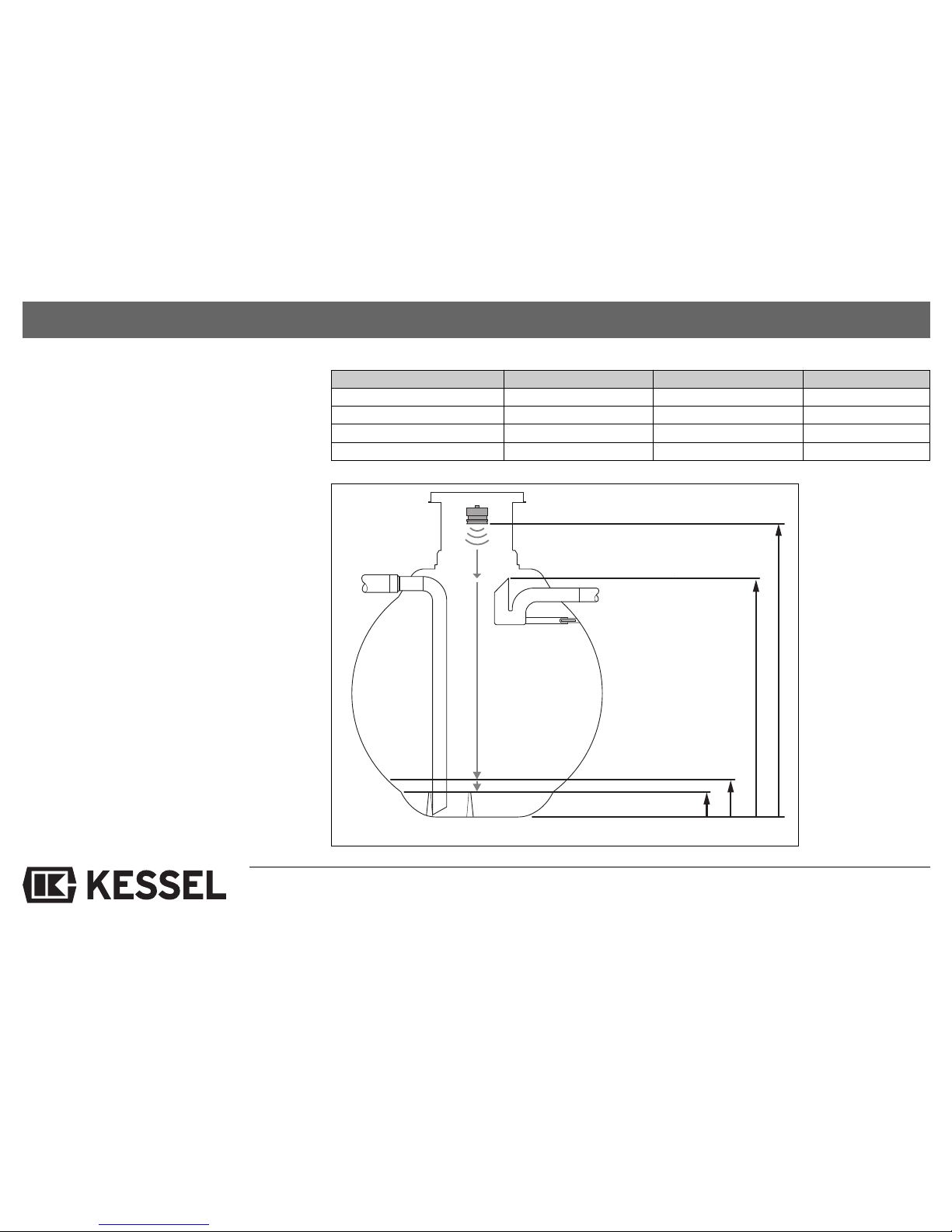
The levels and switching points in the
tank (see following diagrams)
The ultrasound sensor must be secured
with the bracket.
The connection cable must be secured
with strain relief (cable grip).
5.3 Installing the leakage probe
Note and follow the "Safety
Instructions" chapter!
Install the leakage probe as given in the
original operating instructions.
Page 12
12
5. Installation
5.4 Levels and switching points
in the tank
Important!
Tank height >= RSP + 15cm > OSP >=
USP + 1cm
Set value range
50-500 cm
35-485 cm
10-60 cm
0-50 cm
Factory setting
No default setting
No default setting
21 cm
20 cm
Pers. Ein stellung in cm
Set point
Tank height
Backwater switching point RSP
Upper switching point OSP
Lower switching point USP
Tank height
Backwater switching point RSP
Upper switching point OSP
Lower switching point USP
Page 13
13
6. Electrical Connection
Important!
To be connected by a qualified electrician only. Comply with the relevant, currently valid regulations, laws and standards. Also read and follow the "Safety
Instructions" chapter. The seals of the
cable glands which are not used, i.e. no
cable is connected through them, may
not be penetrated. They help to seal the
housing.
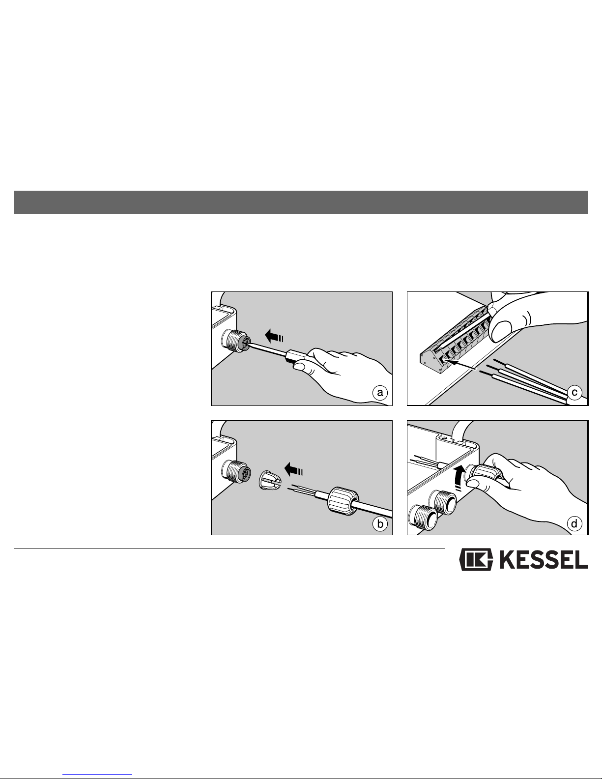
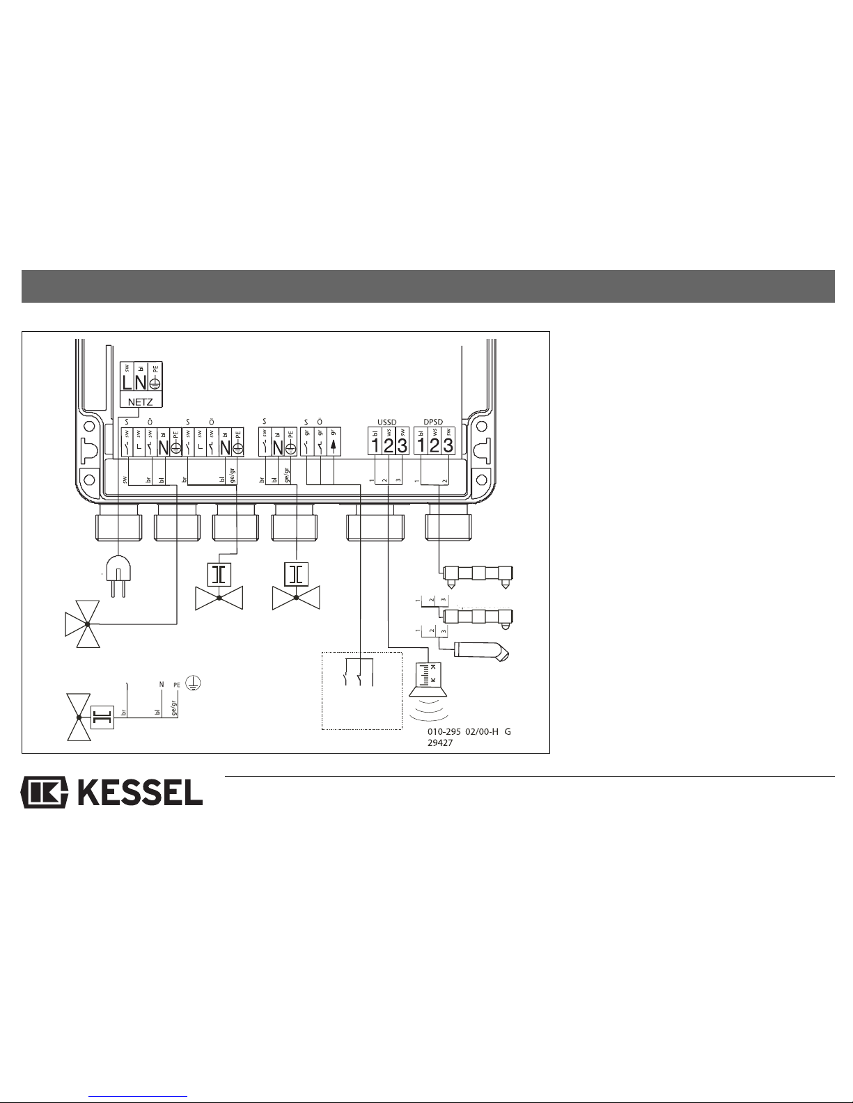
The connection lead of the ultrasound sensor must be connected in accordance with
the circuit diagram (see next page). First,
use a screwdriver to push through the cable
gland seal concerned (Figure a), feed
through the cable (Figure b) and connect
(Figure c).
Then tighten the nut of the cable gland by
hand (Figure d).
Note the technical specifications when
connecting the drinking water top-up supply, outputs 1 and 2, the floating contact and
the leakage probe. Use products approved
by the manufacturer only. Otherwise the
above text applies.
Do not penetrate the seals of the cable
glangs which are not used, i.e. through
which a cable is not connected. They
help to seal the housing
Page 14
14
6. Electrical Connection
Important!
To be connected by a qualified electrician only.
Comply with the relevant, currently
valid regulations, laws and standards.
Also read and follow the "Safety Instructions" chapter.
If the potential free contact is connected, a very dangerous interference voltage may exist at the terminals, even if
the mains plug has been disconnected.
If the potential free contact is connected with 230 VAC the same phase must
be used as for the mains connection.
ZE = additional equipment
ZLT = central measurement and control
Connection plan
Mains
230 ~
50 Hz
3-way changeover valve 230 ~
50 Hz
Solenoid valve,
drinking water
top-up
230 ~ 50 Hz
Solenoid valve,
rainwater filter
rinsing
230 ~ 50 Hz
Solenoid valve,
operating safety
230 ~ 50 Hz
Floating contact
Ultrasound sensor
Leakage probe
(conductivity probe)
Leakage probe
(optical probe)
optical probe
Page 15

7.1 Initial start-up
Note and follow the "Safety Instructions" chapter!
If all the electrical and mechanical components have been properly connected, the
system can now be put into service.
Plug the mains plug into the earthing
socket.
The switching device displays the cur-
rent version number.
Soon after, "HHH" appears.
Press the "T" button
020" appears in the display
An acoustic signal is emitted.
Use the "▲" and "▼" buttons to set the tank
height in cm.
Press the "T" button for more than 2 se-
conds to confirm the value.
An acoustic signal is emitted.
Value has been saved
The device is in normal operation. After a
short time the current water level is displayed in cm. The green LED for normal operation is lit. The device is running with the default factory settings. These are shown in
the table "5.4 Default factory settings"
7.2 Normal operation:
In normal operation, the switching device
compares the water level in the tank with
the set switching points. If there is sufficient
water in the rainwater tank (water level
above the USP) the system runs in rainwater mode, i.e. when a fixture (i.e. toilet, faucet) connected to the service water system
is opened, rainwater is pumped into the
pipe network. If the water level falls below
the USP, the drinking water top-up is automatically activated until the water level has
reached the OSP. Activation of the drinking
water top-up is indicated by the orange drinking water top-up LED.
7.3 Manual drinking water top-up
(TWvH)
The "T" button can be used to switch on
drinking water top-up (TWvH). TWvH automatically switches off after a defined time.
The TWvH time is stored in set point E02
and can be changed at any time. During
TWvH the remaining time in minutes appears in the display. The decimal points of
the display flicker and the orange drinking
water top-up LED is lit. The TWvH can be
switched off manually at any time.
15
7. Commissioning
Page 16

7. Commissioning
16
7.4 Other functions:
a) Backwater switching point
This has a different effect on the drinking
water top-up depending on the two system
types:
Aqabull:
Drinking water top-up is switched on automatically. The non-potable water system is
supplied directly from the drinking water
top-up tank until the error is acknowledged
at the switching device.
Aqadive:
Drinking water top-up is blocked until the
error is acknowledged at the switching device.
b) Rainwater filter rinsing
The rainwater filter is rinsed at regular intervals. Activation of this function and the
times for the rinsing interval and duration
can be set as required. Rainwater filter rinsing can be switched on manually at any
time.
c) Detection of leaking water
If the leakage probe detects water, the
drinking water top-up, output 1, output 2,
the floating contact and the acoustic alarm
are affected according to the selected settings.
d) The floating contact
The floating contact is used to signal a
mains power failure or error.
e) Sensitivity of the ultrasound sensor
The sensitivity of the ultrasound sensor
can be adjusted to match the installation
conditions.
Page 17
17
7. Commissioning
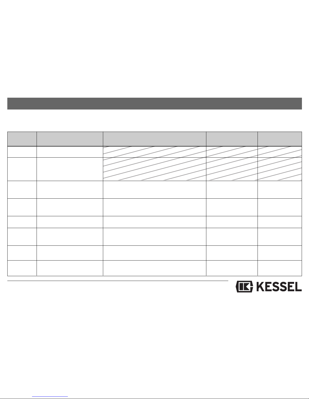
7.5 Default factory settings
Set point Significance Range of the set values Factory setting Your personal
setting
E00 Master reset
E01 The device determines the
distance to the surface of
the water in cm
E02 Manual drinking water
top-up time 001 to 999 = 1 - 999 minutes 001 = 1 minute
E03 System type 000 = Aqadive
001 = Aqabull 001
E10 Tank height 050 bis 500 = 50 - 500 cm No default setting
E11 Lower switching point USP,
drinking water top-up 000 bis 050 = 0 - 50 cm 020 = 20 cmg
E12 Upper switching point OSP 010 bis 060 = 10 - 60 cm
drinking water top-up OSP >= USP + 1cm 021 = 21cm
E13 Backwater switching point 035 bis 485 = 35 - 485 cm
RSP tank height >= RSP + 15cm No pre-setting
Page 18
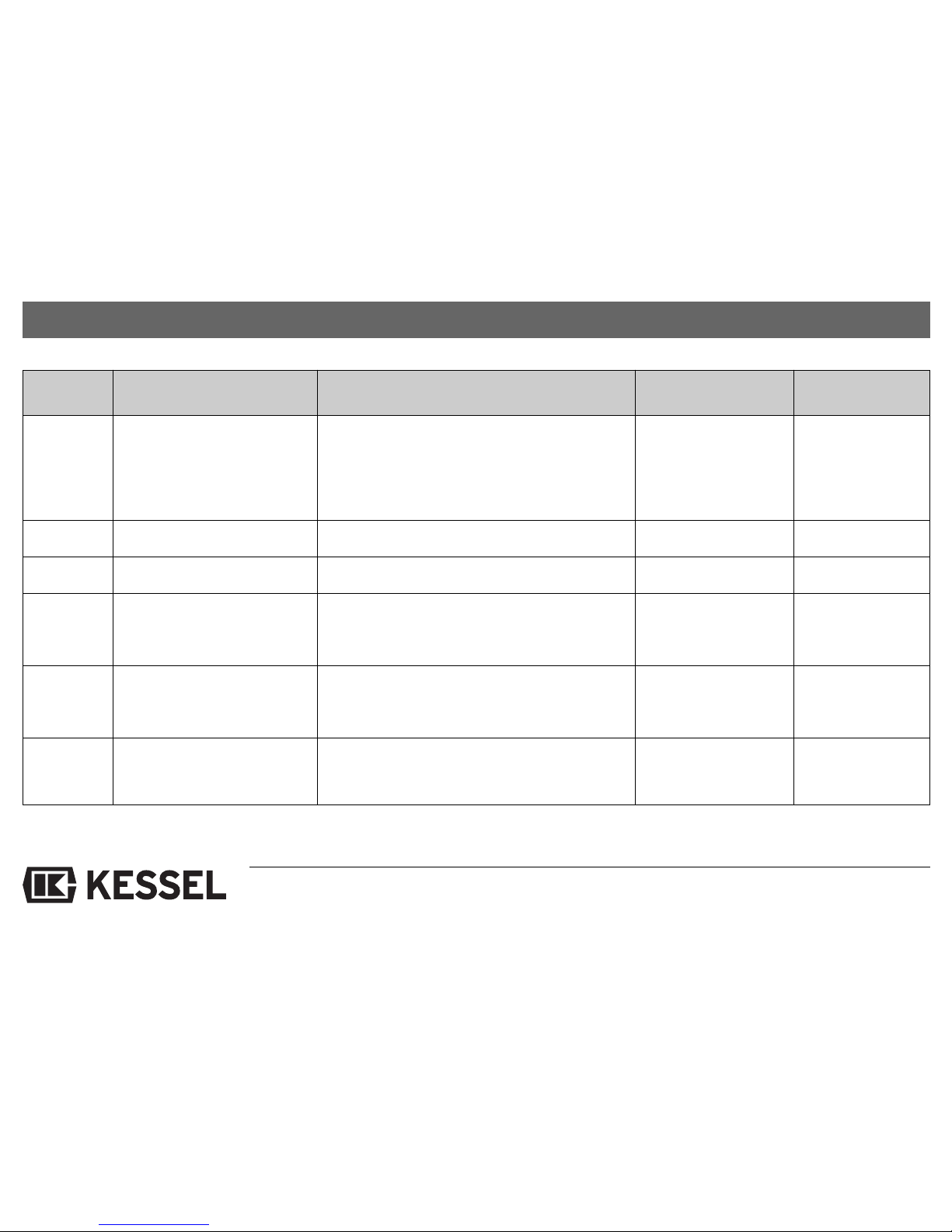
Set point Significance Range of the set values Factory setting Your personal
setting
E20 Rainwater filter rinsing 000 = Time control inactive 000
001 = Time control active
002 = Immediate operation active, i.e.
rinsing starts immediately
E23 Time interval of the rinsing 001 bis 020 = 1 - 20 weeks 001 = 1 week
E24 Rinsing duration 001 bis 999 = 1 - 999 seconds 030 = 30 seconds
P40 Leakage probe 000 = no leakage probe installed 000
001 = leakage probe is an optical probe
002 = leakage probe is a conductivity probe
P41 Effect on drinking water 000 = no effect 000
top-up if leaking water is 001 = switch on drinking water top-up
detected 002 = switch off drinking water top-up
P42 Effect on rainwater filter 000 = no effect 000
rinsing if leaking water is 001 = switch on rainwater filter rinsing
detected 002 = switch off rainwater filter rinsing
18
7. Commissioning
Page 19
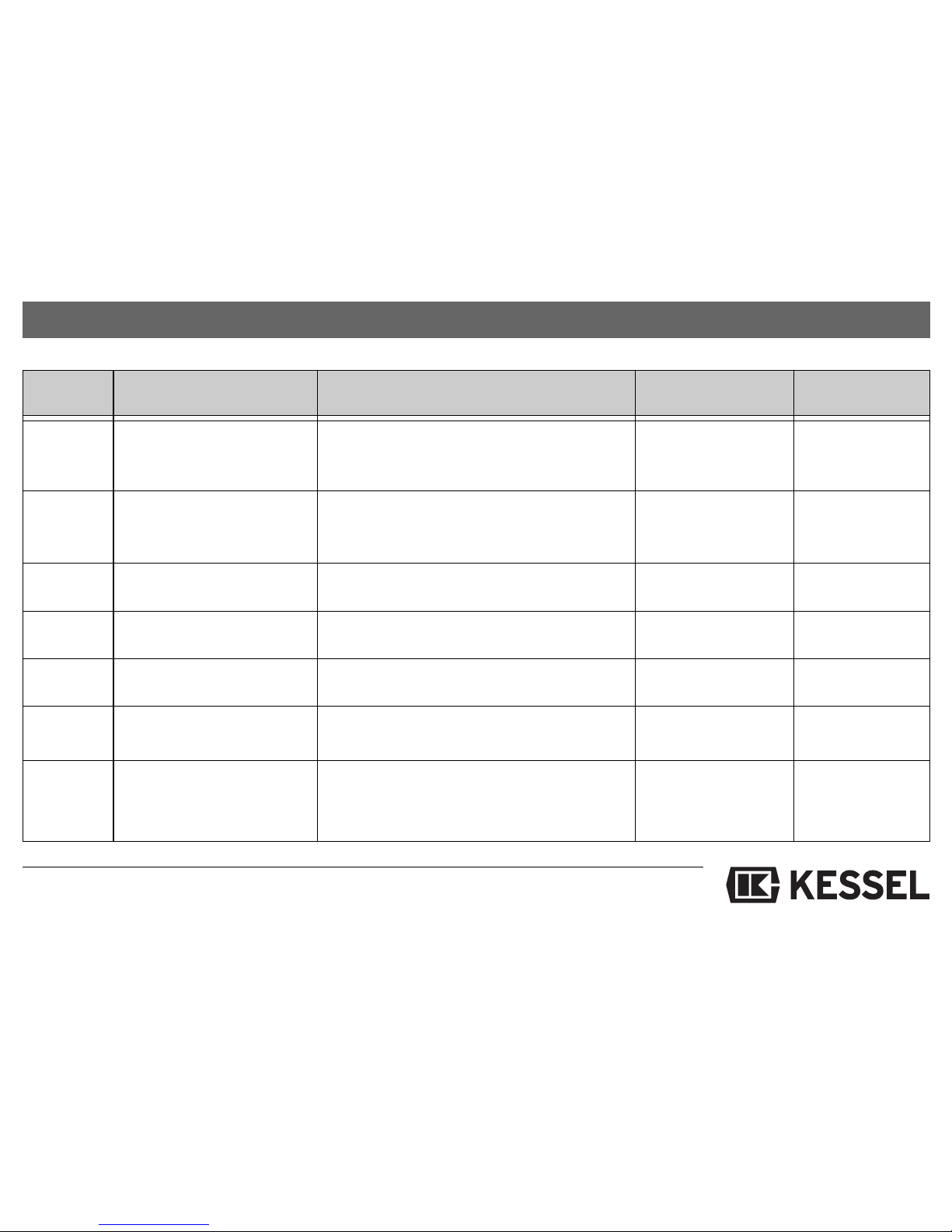
Set point Significance Range of the set values Factory setting Your personal
setting
P43 Effect on operating safety 000 = no effect 002
output water if leaking water 001= switch on operating safety
is detected 002 = switch off operating safety
P44 Effect on the floating contact 000 = floating contact relay remains picked up 001
and acoustic alarm if 001 = floating contact relay drops out
leaking water is detected 001 = acoustic alarm on
P50 Inversion of drinking 000 = not inverted 000
water top-up 001 = inverted
P51 Inversion of rainwater 000 = not inverted 000
filter rinsing 001 = inverted
P53 Inversion of operating 000 = not inverted 001
safety output 001 = inverted
P54 Inversion of floating 000 = not inverted 001
contact relay 001 = inverted
P70 Sensitivity of the 000 to 050; 025
ultrasound sensor 000 = insensitive
050 = sensitive
025 = average sensitivity
7. Commissioning
19
Page 20

7. Commissioning
20
7.6 Checking the set values:
In normal operation the "T", "▲" and "▼" buttons can be used to check set values.
A set value is assigned to each set point
(see default factory settings table).
Important! A master reset is performed
under set point E00. The distance to the
surface of the water is measured under
set point E01.
Simultaneously press "T", "▲" and "▼"
buttons.
An acoustic signal is emitted and E00
is displayed.
Use the "▲" and "▼" buttons to select the
required set point.
Confirm with "T" button.
The set value is displayed.
Briefly press the "T" button.
The set point is displayed again.
Press the "T" button until an acoustic sig-
nal is emitted.
The device is in normal operation.
If the "T" button is not pressed for 20 seconds, the device automatically switches to
normal operation. At the same time, an
acoustic signal is emitted.
7.7 Changing the set values:
In normal operation the "T", "▲" and "▼" buttons can be used to change set values.
A set value is assigned to each set point
(see default factory settings table).
Important! A master reset is performed
under set point E00. The distance to the
surface of the water is measured under
set point E01.
Page 21

21
7. Commissioning
Simultaneously press "T", "▲" and "▼"
buttons.
An acoustic signal is emitted and E00
is displayed.
Use the "▲" or "▼" button to select the re-
quired set point.
Confirm with the "T" button.
The set value is displayed.
Use the "▲" and "▼" buttons to change the
required set value.
Press the "T" button until an acoustic sig-
nal is emitted.
The set value is saved.
The set point is displayed again.
Press the "T" button until an acoustic sig-
nal is emitted.
The device is in normal operation.
If the "T" button is not pressed for 20 seconds, the device automatically switches to
normal operation without saving any changes.
At the same time, an acoustic signal is emitted. The device allows meaningful values
only for the tank height and switching points.
Tank height > RSP > OSP > USP.
After a mains power failure the set values
changed by you are retained.
7.8 Master reset
Important! A master reset deletes all the
set values entered by the user. Before
triggering the master reset, the whole system must be checked for possible resulting hazards. The factory setting is
stored in the switching device, BUT, the
system type setting (Aqadive or Aqabull)
is retained.
Simultaneously press "T", "▲" and "▼"
buttons.
An acoustic signal is emitted and E00
is displayed.
Press "T" button.
"– – –" appears in the display.
Simultaneously press the "▲" and "▼" but-
tons until an acoustic sound is emitted.
"HHH" appears in the display.
The master reset has been performed
and the factory setting is saved.
See item 7.1 Initial start-up for a descrip-
tion of further steps to be taken.
Page 22
22
8. Malfunctions and Corrective Action
Malfunctions are displayed and signalled by
an acoustic alarm. The alarm tone can be
acknowledged with the "T" button, but the
error message stays displayed. When the
error has been corrected it can be acknowledged by extended pressing of the "T".
8.1 Possible types of error
8.2 Troubleshooting
Read and follow the "Safety Instructions" and "Inspection and Maintenance" chapters!
Meaningful tank height and switching point
values are necessary conditions for the
troubleshooting.
Error A - 1 (malfunction):
The water level in the tank has exceeded
the backwater switching point RSP.
It is possible that the tank has been flooded
due to backwater from the sewer and wastewater containing faecal matter is in the
tank. The water quality must be checked. If
in doubt, contact your customer service
partner.
Aqabull response:
The drinking water top-up is automatically
switched on. The non-potable water system
is supplied directly from the drinking water
top-up tank until the error is acknowledged
at the switching device.
Aqadive response:
Drinking water top-up is blocked until the
error is acknowledged at the switching device.
Error A - 2 (malfunction):
Leaked water has been detected by the leakage probe. Please check the place where
the leakage probe is attached immediately.
If in doubt, contact your customer service
partner.
Error- Error type
Code
A - 1
Backwater switching point RSP
has been reached
A - 2
Leakage probe signals leaked
water
A - 3
Ultrasound sensor or leakage
probe signal error
A - 4
Ultrasound sensor receives
no echo
A - 5
Ultrasound sensor measures
value which is too large
Page 23
23
8. Malfunctions and Corrective Action
Error A - 3 (device error): Error A - 4 (device error):
Ultrasound sensor receives no echo. The
water level cannot be measured. Check ultrasound sensor for dirt and alignment.
Check whether there are any obstructions
between the ultrasound sensor and the surface of the water.
A further cause of errors can be excessive
disturbance/waves in the tank, check the
inlet calming device is working properly.
Error A - 5 (device error):
The ultrasound sensor measures a value
which exceeds the tank height.
Check the ultrasound sensor is properly aligned.
An echo is also not returned if the base of
the tank is uneven.
8.3 Simultaneous errors
If two or more errors occur simultaneously,
only one error can be displayed. A priority
has been assigned to the types of errors to
simplify the troubleshooting. The error with
the highest priority is always displayed. If it
has been corrected and acknowledged with
the "T" button, the error with the next highest priority is displayed.
Sensor type: Cause of error:
Ultrasound sensor Technical defect
Incorrectly connected
Short-circuit in the
connection lead
Interruption (break) in
the connection lead
Leakage probe Technical defect
Incorrectly connected
Short-circuit in the
connection lead
Interruption (break) in
the connection lead
Probe type incorrectly
entered
Ranking Error code:
1 (high) A - 2
2 A - 1
3 A - 4
4 A - 3
5 (low) A - 5
Page 24

24
9. Inspection and Maintenance
Note and follow the "Safety Instructions"
chapter!
All the inspection and maintenance work described in the following may be carried out
by authorised, skilled personnel only.
Repairs may be carried out by the manufacturer only.
The switching device does not require any
maintenance.
The ultrasound sensor must be checked for
dirt and its alignment at regular intervals. Al-
ways handle the sensor with care. The sensor can be cleaned with mild soapsuds and
a brush.
The connection leads must be checked for
damage. If any damage is found, the system
must be shutdown immediately.
Page 25

25
10. Warranty
1. In the case that a KESSEL product is defective, KESSEL has the option of repairing
or replacing the product. If the product remains defective after the second attempt to
repair or replace the product or it is economically unfeasible to repair or replace the
product, the customer has the right to cancel the order / contract or reduce payment
accordingly. KESSEL must be notified immediately in writing of defects in a product.
In the case that the defect is not visible or
difficult to detect, KESSEL must be notified
immediately in writing of the defect as soon
as it is discovered. If the product is repaired
or replaced, the newly repaired or replaced
product shall receive a new warranty identical to that which the original (defective)
product was granted. The term defective
product refers only to the product or part
needing repair or replacement and not necessarily to the entire product or unit. KESSEL products are warranted for a period of
24 month. This warranty period begins on
the day the product is shipped form KESSEL to its customer. The warranty only applies to newly manufactured products. Additional information can be found in section
377 of the HGB.
In addition to the standard warranty, KESSEL offers an additional 20 year warranty
on the polymer bodies of class I / II fuel separators, grease separators, inspection
chambers, wastewater treatment systems
and rainwater storage tanks. This additional
warranty applies to the watertightness, usability and structural soundness of the product.
A requirement of this additional warranty is
that the product is properly installed and
operated in accordance with the valid installation and user's manual as well as the
corresponding norms / regulations.
2. Wear and tear on a product will not be con-
sidered a defect. Problems with products
resulting from improper installation, handling or maintenance will also be considered
a defect.
Note: Only the manufacturer may open sealed components or screw connections.
Otherwise, the warranty may become null
and void
01.06.2010
Page 26
EC DECLARATION OF CONFORMITY
Device / Type: KESSEL Aqatronic®K switching device
We herewith confirm that the product described above conforms to the essential health and safety require-
ments defined in the Council Directive on the approximation of the laws of the Member States relating to el-
ectromagnetic compatibility (89/336/EEC) as well as in the Council Directive on the harmonization of the
laws of Member States relating to electrical equipment designed for use within certain voltage limits
(73/23/EEC).
The following standards were used to assess the products with respect to electromagnetic compatibility:
EN 50081-1:1992
EN 50082-1:1992
The following standards were used to assess the products with respect to electrical safety:
DIN EN 60335-1:1995-10
DIN EN 60730-1:1996-01
Kessel GmbH, Bahnhofstraße 31, D-85101 Lenting
Lenting 01.02.2002
B. Kessel G. Vanetta
26
Page 27

11. Handover Certificate
Type designation*
KESSEL order number *
Production date *
(* according to rating plate/invoice)
Product name / system owner/operator
Address / Phone / Fax
Designer / Address / Phone / Fax
Installation firm
Address / Phone / Fax
Electrical firm
Address / Phone / Fax
Authorised acceptance representative
Address / Phone / Fax
Person handing over
Other comments
The putting into service according to the EBA and instruction was carried out in the presence of the authorised acceptance representative and the system owner/operator.
______________________________ ______________________________ _________________________
Town/City, Date Signature of authorised acceptance representative Signature of system owner/operator
27
Page 28

E v e r y t h i n g f o r D r a i n a g e
Anti-flooding devices
Pumps / Lifting stations
Drains
made of Ecoguss
made of plastic
made of stainless steel,
Stainless steel gutters
Separators
Grease separators
Oil/petrol interceptors
Starch separators
Sediment traps
Small wastewater
treatment systems
Manholes
Rainwater harvesting
systems
 Loading...