

Page 1
Sauter GmbH
Ziegelei 1
D-72336 Balingen
E-Mail: info@sauter.eu
Tel: +49-[0]7433- 9933-199
Fax: +49-[0]7433-9933-149
Internet: www.sauter.eu
Instruction Manual
HMR
DIGITAL LEEB HARDNESS TESTER
Model: HMR
Table of contents
1. Overview
1.1 HMR Advantages
1.2 Main Application & Testing Range
1.2.1 Main Application
1.2.2 Testing Range
1.3 Configuration
1.4 Working Conditions
2. Structure Feature & Testing Principle
2.1 Structure Feature
2.1.1 Hardness Tester Appearance
2.1.2 Parts of the Main body
2.1.3 D Type Impact Device
2.1.4 Different types of Impact Devices
2.2 Leeb Hardness Testing Principle
3. Technical Specifications
4. Preparation & Testing
4.1 Preparation and Inspection before Testing
4.1.1 Preparation of Sample Surface
4.1.2 System Setting
4.1.3 Presetting Testing conditions
4.2 Testing Program
4.2.1 Start-up
4.2.2 Testing
4.2.3 Reading the Measured Value
4.2.4 Power Off
5. Advice
6. Operation in Details
6.1 Power On
6.2 Power Off
6.3 Testing
6.3.1 Full description of the Main Display
6.3.2 Testing Operation at the Main Display
6.3.3 Key Operation at the Main Display
6.4 Menu Structure
6.5 Test Set
6.5.1 Impact Direction Setting
6.5.2 Average Times Setting
6.5.3 Material Setting
6.5.4 Hardness Scale Setting
6.5.5 Tolerance Limit Setting
6.5.6 Hardness / б b Setting
6.6 Print Set
6.7 Memory Management
6.7.1 View from No.1 Group/ View from Ending Group
6.7.2 View from Selected No. Group
6.7.3 Data Transfer
6.7.4 Delete by Group No.
6.7.5 Delete all Data
6.7.6 Deletion Confirmation
6.8 Browsing Memory Data Groups
6.9 System Reset
6.9.1 LCD Brightness Setting
6.9.2 Date/ Time Setting
6.10 Software Information
6.11 System Calibration
6.12 EL Background Light
6.13 Auto Power Off
6.14 Battery Replacement
6.15 Connection of Data Transmission Cable
7. Fault Analysis & Fault Clearance
8. Servicing & Maintenance
8.1 Impact Device Servicing
8.2 Normal Maintenance Program
9. Calibration
10. Transport and Storage Conditions
11. Declaration of Conformity
APPENDIX
Table 1
Table 2
Table 3
Table 4
1. Overview
1.1 HMR Advantages
Wide measuring range based on the principle of
Leeb Hardness testing theory. Leeb Hardness of
all metallic materials can be measured.
Large screen (128 x 64 dot matrix LCD) showing
all functions and parameters.
Testing at any angle, even upside down
With EL background light
Direct display of hardness scales HRB, HRC,
HV, HB, HS, HL
Seven impact devices are available for special
applications. Automatical identification of type of
impact devices
Large capacity memory can store 500 groups,
information including single measured value,
mean value, testing date, impact direction,
impact times, material, hardness scale etc.
Upper and lower limit can be preset. It will alarm
automatically if the result value is exceeding the
limit.
Battery information: rest capacity of battery is
indicated.
HMR-BA-e-1212 1
Page 2
Sauter GmbH
Ziegelei 1
D-72336 Balingen
E-Mail: info@sauter.eu
Tel: +49-[0]7433- 9933-199
Fax: +49-[0]7433-9933-149
Internet: www.sauter.eu
Instruction Manual
HMR
No.
Item
Qua
ntity
Remarks
Stan
dard
Config
uration
1
Main body
1
2
D type impact
device
1
With cable
3
Standard test
block
1 4
Cleaning brush
(I)
1
5
Small support
ring
1
6
Alkaline battery
4
AA size
7
Manual
1 8
Instrument case
1 9
Optio
nal
Config
uration
11
Cleaning brush
(II)
1
For use with G
type impact
device
12
Other type of
impact devices
and support
rings
Refer to Table 3
and Table 4 in
the appendix.
13
DataPro for
HL200 software
1 14
Communication
cable
1
Software calibration function
Software to connect with PC and USB port
Compact metal case, suitable for use under poor
working conditions
Continuous working period of not less than 50
hours with two Alkaline batteries (AA size);
Auto Power Off to save energy
Dimensions: 132 mm x 76.2 mm
Weight: 345 g
1.2 Main Application & Testing Range
1.2.1 Main Application
Die cavity of molds
Bearings and other parts
Failure analysis of pressure vessels, steam
generators and other equipment
Heavy work piece
Testing the surface of a small hollow space
Material identification in the range of metallic
materials
1.2.2 Testing Range
Please refer to Table 1 and Table 2 in the APPENDIX.
1.3 Configuration
Table 1-1
2. Structure Feature & Testing Principle
2.1 Structure Feature
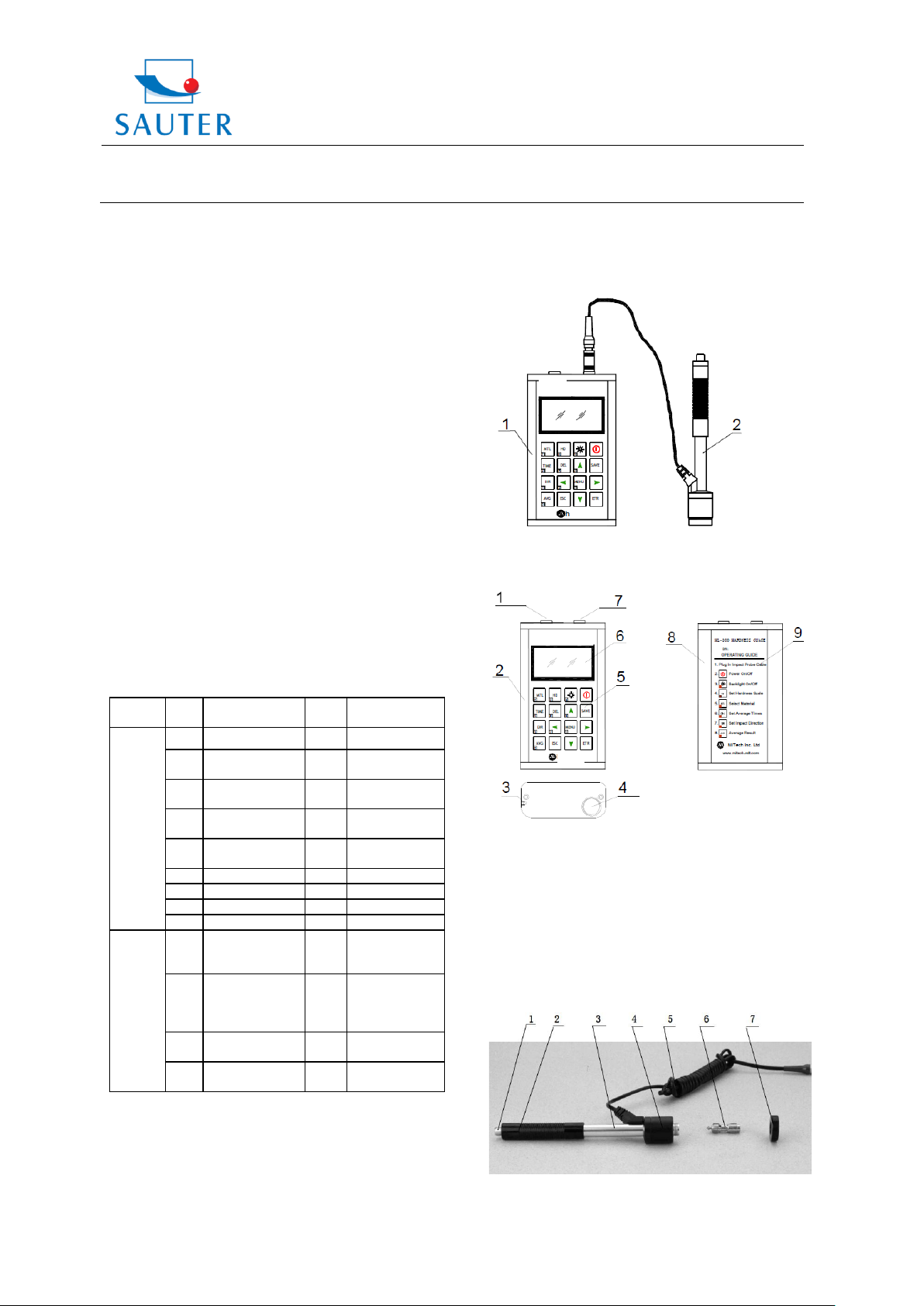
2.1.1 Hardness Tester Appearance
1. Main body 2.Impact device
2.1.2 Parts of the Main body
1.4 Working Conditions
Working Temperature: 0°C up to +40°C
Storage Temperature: -30°C up to +60°C
Relative humidity: ≤ 90%
Vibrations, strong magnetic field, corrosive medium and
heavy dust should be avoided in the surroundings.
HMR-BA-e-1212 2
1 Socket of USB
2 Aluminium case
3 Belt hole
4 Battery cover
5 Keypad
6 LCD Display
7 Socket of Impact Device
8 Aluminium case, (backside)
9 Label (backside)
2.1.3 D Type of Impact Device
1. Release button
2. Loading Tube
Page 3
Sauter GmbH
Ziegelei 1
D-72336 Balingen
E-Mail: info@sauter.eu
Tel: +49-[0]7433- 9933-199
Fax: +49-[0]7433-9933-149
Internet: www.sauter.eu
Instruction Manual
HMR
N
o
.
Typ
e of
im
pact
devi
ce
Hardness value
of Leeb
standard
hardness block
Error of
displayed
value
Repeata
bility
1
D
760±30HLD
530±40HLD
±6 HLD
±10 HLD
6 HLD
10 HLD
2
DC
760±30HLDC
530±40HLDC
±6 HLDC
±10 HLDC
6 HLD
10 HLD
3
DL
878±30HLDL
736±40HLDL
±12 HLDL
12 HLDL
4
D+
15
766±30HLD+15
544±40HLD+15
±12
HLD+15
12
HLD+15
5
G
590±40HLG
500±40HLG
±12 HLG
12 HLG
6
E
725±30HLE
508±40HLE
±12 HLE
12 HLE
7
C
822±30HLC
590±40HLC
±12 HLC
12 HLC
3. Guide Tube
4. Coil unit
5. Connection cable
6. Impact body
7. Support ring
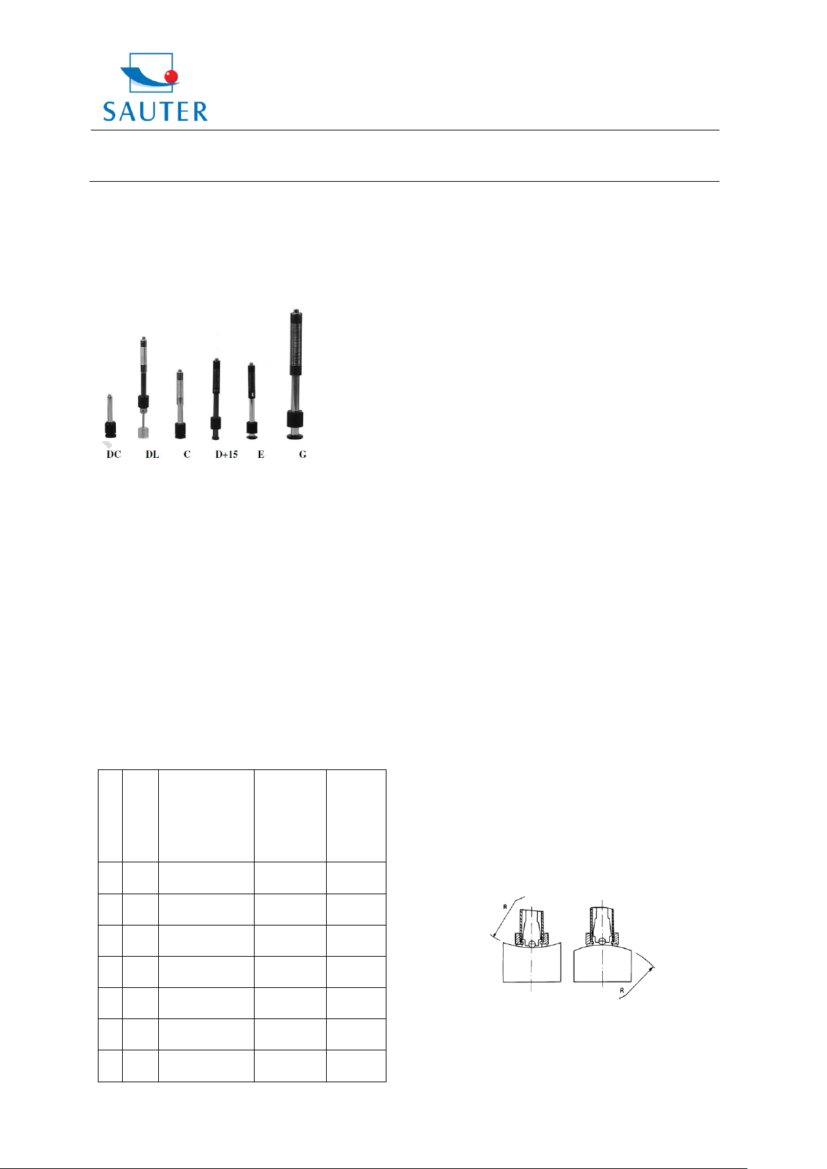
2.1.4 Different types of Impact Devices
2.2 Leeb Hardness Testing Principle
The basic testing principle is to use an impact body of a
certain weight which impacts against the testing surface
under certain test force. The impact velocity and the
rebound velocity of the impact body are measured
respectively when the spherical test tip is located 1mm
above the surface being tested.
The calculation formula is as follows:
HL= 1000 x VB/VA
Where HL= Leeb Hardness Value
VB= Rebounding velocity of the impact body
VA= Impact velocity of the impact body
3. Technical Specifications
Error and repeatability of the displayed value,
see Table 3-1:
HMR-BA-e-1212 3
Measuring range: HLD: (170 ~ 960) HLD
Measuring direction: 0 ~ 360°
Hardness Scale: HL, HB, HRB, HRC, HRA,
HV, HS
Display: dot matrix LCD,128 x 64 dots
Data memory: max. 500 groups
Power supply: 3V, (2AA size Alkaline batteries)
Continuous working period: about 50 hours
(with backlight off)
Communication interface: USB1.1
4. Preparation & Testing
4.1 Preparation and Inspection before Testing
4.1.1 Preparation of Sample Surface
Preparation of the sample surface should conform to the
relative requirements in APPENDIX Table 3.
During the preparation of the sample surface,
any heating or cold processing on this surface
should be avoided.
Too big roughness of the surface being
measured could cause errors. The surface of the
sample should show metallic luster, be smooth
and polished, without any stains of oil etc.
Support of the sample is not necessary for
heavy objects. Medium-weight samples have to
be placed onto a smooth and stable plane. It
must be placed in absolute equability and
without any wobble.
Curved surface: The best testing surface, of
course, is flat. When the curvature radius R of
the surface to be tested is smaller than 30 mm
(D, DC, D+15, C, E and DL type of impact
device) and smaller than 50 mm (G type of
impact device), the small support rings should
be chosen.
The sample should have enough thickness, the
minimum thickness of it should conform to
Table 3.
*For a sample with a hardened layer on its surface,
the depth of the hardened layer should also conform
to Table 3.
Coupling: Light-weight samples must be firmly
coupled with a heavy base plate. Both coupled
surfaces have to be flat and smooth; there may
not rest any redundant coupling agent. The
impact direction must be vertical to the coupled
Page 4
Sauter GmbH
Ziegelei 1
D-72336 Balingen
E-Mail: info@sauter.eu
Tel: +49-[0]7433- 9933-199
Fax: +49-[0]7433-9933-149
Internet: www.sauter.eu
Instruction Manual
HMR
surface. If the sample is a big plate, long rod or
bending piece, it can be deformed and become
unstable, even though its weight and thickness
is big enough; accordingly, the test value might
not be accurate. So the sample should be
reinforced or supported at its back.
Magnetism of the sample itself should be
avoided.
4.1.2 System Setting
See 6.9 for details.
4.1.3 Presetting Testing conditions
See 6.5 for details.
4.2 Testing Program
The hardness tester has to be verificated by using the
hardness block. The error and repeatability of the
displayed value should be within the regulation of
APPENDIX Table 2.
4.2.1 Start-up
1) The plug of the impact device has to be inserted into the
socket of the impact device of the instrument.
2) The key has to be pressed to power on. Now the
instrument is in testing condition.
4.2.2 Testing
- The release button on the upside of the impact device
has to be pressed to start testing. The sample and the
impact device as well as the operator are all required to be
stable now. The action direction should pass the axis of
the impact device.
- Each measurement area of the sample usually needs 3
to 5 times of testing operations. The result data dispersion
should not be more than the mean value ± 15 HL.
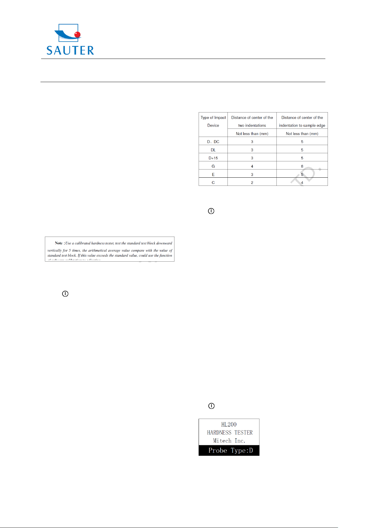
- The distance between any two impact points or from the
centre of any impact point to the edge of the sample
should conform to the regulation of Table 4-1.
- If an accurate conversion from the Leeb hardness value
to another hardness value is requested, a contrastive test
is needed to get conversion relations for the special
material. An inspected qualified Leeb hardness tester and
a corresponding hardness tester have to be used to test at
the same sample respectively. For each hardness value,
each homogeneous measurement, 5 points of Leeb
hardness value are needed. They are in the surroundings
of more than three indentations which need conversion of
hardness. The Leeb hardness arithmetic average value
and the corresponding hardness average value as
correlative value respectively are used to establish an
individual hardness contrastive curve. The contrastive
curve at least should include three groups of correlative
data.
Table 4-1
4.2.3 Reading the Measured Value
4.2.4 Power Off
The key has to be pressed to power off.
5. Advice
- The impact device must be replaced during the
instrument is powered off. Otherwise the type of impact
device cannot be identified by the main body. The circuit
board of the main body may get damaged.
- If the testing times are less than the preset times value,
the current test value can not be saved. 【 AVG 】 can be
pressed to end the testing process in advance if the values
shall be saved.
- When pressing 【 AVG 】 to end testing in advance, the
【 Auto save】 , 【 Auto transfer】 settings will not work.
- Only D and DC type of impact device have got the
function of strength measurement. Using other types of
impact device, the 【 Set hardness orбb 】 can not be
modified. The 【 Set hardness orбb 】 setting will be set
to【 Hardness 】 automatically after replacing the impact
device, whether the setting is【 Hardness 】 or not before.
- Not all materials can be converted to all hardness style
values. The hardness style is reset to HL automatically
after changing material. So, material has to be selected
first before changing the hardness style.
6. Operation in Details
6.1 Power On
The key has to be pressed to power on the instrument.
Following is shown on the screen:
The type of impact device will automatically be detected
during powering on. This information will be displayed on
the screen (Probe Type). After several seconds, the
HMR-BA-e-1212 4
Page 5

Sauter GmbH
Ziegelei 1
D-72336 Balingen
E-Mail: info@sauter.eu
Tel: +49-[0]7433- 9933-199
Fax: +49-[0]7433-9933-149
Internet: www.sauter.eu
Instruction Manual
HMR
Material
Average value
indicator
Hardness
scale
Meas
ured
value
Impact times
count
Impact
direction
Battery
Inform.
screen will exit and the main display interface will be
entered.
6.2 Power Off
By pressing the key the system can be powered off in
any state.
6.3 Testing
Below, the main display is shown:
6.3.1 Full description of the Main Display
Battery information: displays the rest capacity of the
battery.
Impact direction: displays the present impact direction.
Average value indicator: it appears to show the mean
value when the preset impact times are reached.
Hardness scale: Hardness method of the present
measured value.
Measured value: displays the present single time
measured value (without mean value indicator), or displays
the present mean value (with average value indicator
prompting). ↑ means that the value is over conversion or
measurement range. ↓ means that it is lower than
conversion or measurement range.
Material: The present preset material.
Impact times count: Times that have been impacted.
6.3.2 Testing Operation at the Main Display
Testing operation can be carried out under this interface.
After each impact operation, the current measured value
can be displayed. Impact times count plus one, the buzzer
will alert a long howl if the measured value is not within the
tolerance limit. As soon as the preset impact times are
reached, the buzzer will alert a long howl. After two
seconds, the buzzer will alert a short howl and the mean
value will be displayed.
6.3.3 Key Operation at the Main Display
- The 【 SAVE 】 key has to be pressed to store the present
group of measured values into memory. This operation is
only valid after displaying the mean value.
- The 【 DEL】 key has to be pressed to delete the latest
single measured value. After pressing this key, on the
screen will be shown following:
The key or the key has to be pressed to
move the cursor to 【 YES 】 or 【 NO 】 .
【 ETR 】 has to be pressed to confirm.
【 ESC 】 has to be pressed to cancel deletion.
- The 【 】 or 【 】 key has to be pressed to display the
single measured value.
- By pressing 【 AVG , testing can be ended although the
preset impact times have not been reached and to display
the average value.
- The background light of LCD has to be switched on and
off by pressing 【 】 .
- 【 MENU 】 has to be pressed to enter the system Preset
Menu.
- By pressing , the impact direction can be preset.
- 【 TIME 】 key has to be pressed to change the impact
times in one group. The impact times count item will be
highlighted when the 【 TIME 】 key has been pressed. The
impact times count value will be added one with each
pressing. The value will roll back to 1 after 32 has been
reached.
- The 【 HD】 key has to be pressed to change the hardness
scale.
- By pressing 【 MTL 】 material setting can be changed.
Presetting the hardness scale, HL is automatically
recovered after material presetting has been changed.
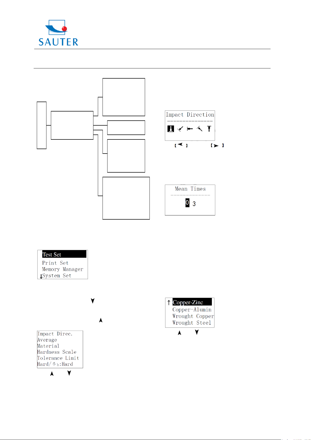
6.4 Menu Structure
Both, presetting system parameters and additional
functions, can be realised by menu operation. At the main
display interface, 【 MENU 】 key has to be pressed to enter
the main menu, as shown in following picture:
HMR-BA-e-1212 5
Page 6
Sauter GmbH
Ziegelei 1
D-72336 Balingen
E-Mail: info@sauter.eu
Tel: +49-[0]7433- 9933-199
Fax: +49-[0]7433-9933-149
Internet: www.sauter.eu
Instruction Manual
HMR
Main display interface
Test Set
Print Set
Memory Manager
System Set
Software Info
Impact Direc.
Average
Material
Hardness Scale
Tolerance Limit
Hard/бb:Hard
(Print Set is NOT
available)
View From No.1
View From End
View From No.
Transfer
Delete by No.
Delete All
Auto Save:
Auto Print:
(N/A)
Auto Delete:
Auto Trans.:
Key Sound:
Warn. Sound:
6.5 Test Set
At the main display interface, 【 MENU 】 key has to be
pressed to enter the main menu.
【 ETR 】 has to be pressed to enter Test Set Menu. The
symbol ↓ at the left side of underside menu indicates that
the menu has not ended. 【 】 key has to be pressed to
glance downward continuously.
The symbol ↑ at the left side of the upside menu indicates
that the menu has not ended. 【 】 has to be pressed to
glance upward continuously.
The 【 】 or 【 】 key has to be pressed to move the
cursor to the desired line to set and 【 ETR 】 has to be
pressed to confirm.
Note: 1. When 【Hard/бb】 is switched to бb, hardness
scale cannot be selected. The cursor will skip over
【
Hardness Scale】while it is moved.
HMR-BA-e-1212 6
2. Only D type of impact device has got the function of
бb measurement. So the cursor cannot be moved to
【
Hard/бb】while another impact device is used.
6.5.1 Impact Direction Setting
The key or the key has to be pressed to
move the cursor to the desired impact direction.
【 ETR 】 has to be pressed to confirm.
【 ESC 】 has to be pressed to cancel.
6.5.2 Average Times Setting
Average times can be modified within the range of 1 to 32.
The 【 0 】 ~ 【 9 】 key has to be pressed to input the
number value. The cursor will shift right around
automatically when inputting the number.
【 ETR 】 has to be pressed to confirm.
【 ESC 】 has to be pressed to cancel.
6.5.3 Material Setting
If 【Hard/бb】is preset to hardness, following material will
be displayed: Steel and Cast Steel, Cold Work Tool Steel,
Stainless Steel, Grey Cast Iron, Nodular Cast Iron, Cast
Aluminium Alloys, Copper-Zinc Alloys, Copper-Aluminium
Alloys, Wrought Copper and Wrought Steel.
The 【 】 or 【 】 key has to be pressed to move the
cursor to the material desired to preset.
【 ETR 】 has to be pressed to confirm.
【 ESC 】 has to be pressed to cancel.
Note: 1. Presetting the hardness scale, HL is
automatically recovered after material presetting has
been changed.
2. Please select material first and then select hardness
scale.
If 【Hard/бb】is preset to бb, following material will be
displayed: Mild Steel, High-Carbon Steel, Cr Steel, Cr-V
Page 7

Sauter GmbH
Ziegelei 1
D-72336 Balingen
E-Mail: info@sauter.eu
Tel: +49-[0]7433- 9933-199
Fax: +49-[0]7433-9933-149
Internet: www.sauter.eu
Instruction Manual
HMR
Steel, Cr-Ni Steel, Cr-Mo Steel, Cr-Ni-Mo Steel, Cr-Mn-Si
Steel, Super Strength Steel and Stainless Steel.
The 【 】 or 【 】 key has to be pressed to move the
cursor to the material desired to preset.
【 ETR 】 has to be pressed to confirm.
【 ESC 】 has to be pressed to cancel.
6.5.4 Hardness Scale Setting
【 ETR 】 has to be pressed to switch between Hard and
бb.
Note: Only D and DC type of impact device have got
the function of бb measurement. So, “Hard” is the only
selection if the impact device is not D or DC type.
6.6 Print Set
At the main display interface, 【 MENU 】 key has to be
pressed to enter the main menu. Printing function is not
available at Hardness Tester HMR.
6.7 Memory Management
At the main display interface, the 【 MENU 】 key has to be
pressed to enter the main menu.
The 【 】 or 【 】 key has to be pressed to move the
cursor to the hardness scale desired to preset.
【 ETR 】 has to be pressed to confirm.
【 ESC 】 has to be pressed to cancel.
Note: 1. Only the valid hardness scale for the present
selected impact device and material are displayed.
An invalid hardness scale will not be displayed.
2. Please select material first and then select hardness
scale.
3. Presetting the hardness scale, HL is automatically
recovered after material presetting has been changed.
6.5.5 Tolerance Limit Setting
The 【 0 】 ~ 【 9 】 key has to be pressed to input the
number value. The cursor will shift right around
automatically when inputting.
【 ETR 】 has to be pressed to confirm.
【 ESC 】 has to be pressed to cancel.
Note: 1. If the preset value exceeds the measurement
range, the user will be reminded by the Tester to reset.
2. If the bottom limit is larger than the upper limit, they
will be exchanged automatically.
6.5.6 Hardness / бb Setting
The 【 】 or 【 】 key has to be pressed to move the
cursor to 【 Memory Manager】 . 【 ETR 】 key has to be
pressed in 【 Memory Manager】 menu. If there is no data in
memory, <No Data!> will be displayed. Then it has to be
returned.
The 【 】 or 【 】 key has to be pressed to move the
cursor to the desired function.
【 ETR 】 has to be pressed to confirm.
6.7.1 View from No.1 Group/ View from Ending Group
【 View From No.1 】 : values in the memory from the first
group are displayed.
【 View From End 】 : values in the memory from the
ending group are displayed.
6.7.2 View from Selected No. Group
The digit figure keys have to be pressed to input the
number.
【 ETR 】 has to be pressed to start displaying memory
data from the selected beginning group.
【 ESC 】 has to be pressed to cancel.
HMR-BA-e-1212 7
Page 8

Sauter GmbH
Ziegelei 1
D-72336 Balingen
E-Mail: info@sauter.eu
Tel: +49-[0]7433- 9933-199
Fax: +49-[0]7433-9933-149
Internet: www.sauter.eu
Instruction Manual
HMR
Auto Save: Off
Auto Print: Off
Auto Delete: Off
Auto Trans: Off
Key sound: On
Warn. Sound: On
LCD Brightness
Time Date Set 日
No.001 12/03 652HL
No.002 12/03 587HL
No.003 12/03 820HL
No.004 12/03 693HL
No.005 12/03 783HL
No.006 12/03 782HL
No.007 12/03 579HL
No.008 12/03 687HL
No.002 12/03 785HL
No.003 12/03 516HL
No.004 12/03 789HL
No.005 12/03 570HL
No.006 12/03 852HL
No.007 12/03 523HL
No.008 12/03 796HL
No.001 12/03 514HL
6.7.3 Data Transfer
【 Transfer 】 has to be pressed to export the values stored
in memory as text format to PC by USB port.
6.7.4 Delete by Group No.
The 【 】 or 【 】 key has to be pressed to see previous
or next page.
【 ESC 】 has to be pressed to exit browsing.
【 ETR 】 has to be pressed and then 【 】 or 【 】 to
move the cursor to the desired line you want to see the
details from. 【 ETR 】 has to be pressed to see details of
that group.
【 Delete by No. 】 :The range of deleted groups is
displayed. The digit figure keys have to be pressed to input
the number.
【 ETR 】 has to be pressed to delete the selected groups.
【 ESC 】 has to be pressed to cancel the operation.
Note: 1.If the present group exceeds the actual range,
the actual groups among them will be deleted!
2. The instrument may not be powered off while
deleting data. This could lead to unpredicted
consequences!
6.7.5 Delete all Data
By pressing 【 Delete All 】 , all data in memory will be
deleted.
6.7.6 Deletion Confirmation
The key or the key has to be pressed to
move the cursor to 【 YES 】 and 【 】 key deletion.
The key or the key has to be pressed to
move the cursor to 【 NO 】 and 【 ETR 】 has to be pressed
to cancel deletion.
【 ESC 】 has to be pressed to cancel deletion, no matter
where the cursor is located.
6.8 Browsing Memory Data Groups
HMR-BA-e-1212 8
The 【 】 or 【 】 key has to be pressed to browse details
including average value, test set and each single value.
【 ESC 】 has to be pressed to return to previous display.
6.9 System Set
At the main display interface, 【 MENU 】 key has to be
pressed to enter the main menu.
【 】 or 【 】 key has to be pressed to move the cursor
to 【 System Set 】 Menu. 【 ETR 】 has to be pressed to
enter 【 System Set 】 Menu.
【 】 or 【 】 key has to be pressed to move the cursor
to the desired item.
By pressing, the setting can be directly modified or into the
corresponding screen. 【 ESC 】 has to be pressed to exit.
【 Auto Save 】 , 【 Auto Delete 】 , 【 Auto Trans. 】 , 【 Key
Sound 】 , 【 Warn. Sound 】 can be switched on or off now.
If 【 Auto Save 】 is set to <On>, according to 3б rule, gross
errors can be cancelled automatically after having
measured preset average times or pressing end in
advance. If there is any data cancelled, it needs
supplemental measurement to reach the preset times.
If 【 Auto Trans. 】 is set to <On>, the value of the present
group can be exported by USB after measuring and
displaying the average value.
If 【 Key Sound 】 is set to <On>, the buzzer will make a
short hoot while a key is being pressed each time.
Page 9

Sauter GmbH
Ziegelei 1
D-72336 Balingen
E-Mail: info@sauter.eu
Tel: +49-[0]7433- 9933-199
Fax: +49-[0]7433-9933-149
Internet: www.sauter.eu
Instruction Manual
HMR
Time Date Set
-------------------10/05/2009 11:02
If 【 Warn. Sound 】 is set to <On>, if the measured value
exceeds the tolerance limit, the preset average times or
deleting data are reached, the buzzer will make a long
hoot.
6.9.1 LCD Brightness Setting
The 【 】 key has to be pressed to enhance brightness.
Brightness can be weakened by pressing 【 】 key.
【 ETR 】 has to be pressed to confirm.
【 ESC 】 has to be pressed to cancel.
6.9.2 Date/ Time Setting
Present time and date are displayed as „M/D/Y H/M“.
The figure (0~9) key has to be pressed to modify the
present figure. The cursor will move automatically from the
left to the right after modifying.
【 ETR 】 has to be pressed to confirm,
【 ESC 】 has to be pressed to cancel modification.
6.10 Software Information
At the main display interface, 【 MENU 】 key has to be
pressed to enter the main menu.
【 】 or 【 】 key has to be pressed to move the cursor
to 【 Software Info 】 . The 【 ETR 】 key has to be pressed to
enter 【 Software Info 】 screen.
This screen displays information about the main body and
the firmware. The version, Code and SN are changing with
the firmware.
6.11 System Calibration
HMR Hardness Tester and the impact device have to be
calibrated by using the hardness block before the first use
or if it hasn’t been used for a longer time or after having
reset the system.
The 【 】 key and the 【 ETR 】 key have to be pressed to
power on the system. Then the software calibration screen
will display following:
The impact direction has to be set at 【 】 .
5 points have to be measured on the standard hardness
block.
The average value will be displayed after measuring 5
times.
【 】 or 【 】 key has to be pressed to input the nominal
value. 【 ETR 】 has to be pressed to confirm,
【 ESC 】 has to be pressed to cancel this operation.
Range of adjustment: ±15HL.
6.12 EL Background Light
By means of the background light it is convenient to work
in dark conditions. 【 】 key has to be pressed to switch
on or off the background light at any time if necessary,
after the instrument is powered on.
6.13 Auto Power Off
- This hardness tester has got the function of powering off
automatically to save power in case if there is neither key
operation nor measurement within 5 minutes. Any key,
except 【 】 key, can be pressed to stop the twinkle of
the LCD screen and thus, stop the operation of powering
off at that moment.
- While the voltage of battery is too low, <Battery empty!>
will be shown on the screen. Then the instrument powers
off automatically.
6.14 Battery Replacement
Two AA size Alkaline batteries are necessary as power
resource. After several hours’ usage, the battery symbol
on the screen will be shown as . The less dark parts
are indicated, the more close to get filled. When the
capacity runs out, the battery symbol will be shown as
and the symbol will begin to flash. Now batteries
have to be replaced.
HMR-BA-e-1212 9
Page 10

Sauter GmbH
Ziegelei 1
D-72336 Balingen
E-Mail: info@sauter.eu
Tel: +49-[0]7433- 9933-199
Fax: +49-[0]7433-9933-149
Internet: www.sauter.eu
Instruction Manual
HMR
M
0
1
2
5
4
8
7
+
-
+
-
An o d e
Ca t ho d e
HA RD
HL -2 00
MT L HD
DE L
TIM E
DIR
ES C
AV G
If batteries are exhausted, they
should be replaced as follows:
- The instrument has to be
powered off.
- The circular battery cover has
to be removed and the batte ries have to be taken off.
- The new batteries have to be
installed and the battery
cover has to be reset.
- The instrument has to be
powered on again to check.
Pay attention to the polarity of the batteries!
The batteries have to be taken out if the instrument
hasn’t been used for a longer period of time.
6.15 Connection of Data Transmission Cable
One connection plug of transmission cable (optional parts)
has to be inserted into the socket on the up left side of the
main body. The other plug has to be inserted into the USB
socket in the back of the computer.
7. Fault Analysis & Fault Clearance
The warranty card has to be filled in and sent to SAUTER
GmbH. The warranty service will be performed within a few
working days.
9. Calibration
The HMR hardness tester has to be calibrated every year.
10. Transport and Storage Conditions
* The instrument has to be kept away from vibration,
strong magnetic field, corrosive medium, dampness and
dust. Safekeeping in ordinary temperature.
DESIGNED IN REGARD TO THESE STANDARDS:
ASTM A956
DIN 50156
11. Declaration of Conformity
8. Servicing & Maintenance
8.1 Impact Device Servicing
After 1000 to 2000 times of usage, the impact
body and the guide tube have to be cleaned with
the provided nylon brush. When cleaning the
guide tube, the support ring has to be
unscrewed first. Then the impact body has to be
taken out. The nylon brush has to be spiralled in
counter-clock direction into the bottom of the
guide tube. It has to be taken out and repeated
for 5 times. At last, the impact body and the
support ring have to be installed again.
The impact body has to be released after use.
Any lubricant is absolutely prohibited inside the
impact device.
8.2 Normal Maintenance Program
* If the standard Rockwell hardness block is used to test
and if all the error is bigger than 2 HRC, the ball top of the
impact device or the impact object may have to be
changed. The invalidation may be caused by abrasion.
* If any other abnormal phenomena appear to the
hardness tester, nothing may be dismantled or any fixed
parts may not be adjusted by the user himself.
HMR-BA-e-1212 10
Page 11

Sauter GmbH
Ziegelei 1
D-72336 Balingen
E-Mail: info@sauter.eu
Tel: +49-[0]7433- 9933-199
Fax: +49-[0]7433-9933-149
Internet: www.sauter.eu
Instruction Manual
HMR
Material
Method
Impact device
D/DC
D+15
C G E
DL
Steel and cast steel
HRC
20~68.5
19.3~67.9
20.0~69.5
22.4~70.7
20.6~68.2
HRB
38.4~99.6
47.7~99.9
37.0~99.9
HRA
59.1~85.8
61.7~88.0
HB
127~651
80~638
80~683
90~646
83~663
81~646
HV
83~976
80~937
80~996
84~1042
80~950
HS
32.2~99.5
33.3~99.3
31.8~102.1
35.8~102.6
30.6~96.8
Cold work tool steel
HRC
20.4~67.1
19.8~68.2
20.7~68.2
22.6~70.2
HV
80~898
80~935
100~941
82~1009
Stainless steel
HRB
46.5~101.
7
HB
85~655
HV
85~802
Grey cast iron
HRC
HB
93~334
92~326
HV
Nodular cast iron
HRC
HB
131~387
127~364
HV
Cast aluminium
alloys
HB
19~164
23~210
32~168
HRB
23.8~84.6
22.7~85.0
23.8~85.5
BRASS (copper-zinc
alloys)
HB
40~173
HRB
13.5~95.3
BRONZE (copperalum./tin alloys)
HB
60~290
Wrought copper
alloys
HB
45~315
No.
Material
HLD
Strength σ
b
(MPa)
1
Mild steel
350~522
374~780
2
High-carbon steel
500~710
737~1670
3
Cr- Steel
500~730
707~1829
4
Cr-V Steel
500~750
704~1980
5
Cr-Ni Steel
500~750
763~2007
6
Cr-Mo Steel
500~738
721~1875
7
Cr-Ni-Mo Steel
540~738
844~1933
8
Cr-Mn-Si Steel
500~750
755~1993
9
Super strength steel
630~800
1180~2652
10
Stainless steel
500~710
703~1676
APPENDIX Table 1
Table 2
HMR-BA-e-1212 11
Page 12

Sauter GmbH
Ziegelei 1
D-72336 Balingen
E-Mail: info@sauter.eu
Tel: +49-[0]7433- 9933-199
Fax: +49-[0]7433-9933-149
Internet: www.sauter.eu
Instruction Manual
HMR
Type of impact device
DC(D)/DL
D+15
C G E
Impact energy
Mass of impact body
11mJ
5.5g/7.2g
11mJ
7.8g
2.7mJ
3.0g
90mJ
20.0g
11mJ
5.5g
Test tip hardness:
Diam. Test tip:
Material of test tip:
1600HV
3mm
Tungsten
carbide
1600HV
3mm
Tungsten
carbide
1600HV
3mm
Tungsten carbide
1600HV
5mm
Tungsten carbide
5000HV
3mm
synthetic diamond
Impact device diameter:
Impact device length:
Impact device weight:
20mm
86(147)/ 75mm
50g
20mm
162mm
80g
20mm
141mm
75g
30mm
254mm
250g
20mm
155mm
80g
Max. hardness of sample
940HV
940HV
1000HV
650HB
1200HV
Mean roughness value of
sample surface Ra:
1.6μm
1.6μm
0.4μm
6.3μm
1.6μm
Min.weight of sample:
Measure directly
Need support firmly
Need coupling tightly
>5kg
2~5kg
0.05~2kg
>5kg
2~5kg
0.05~2kg
>1.5kg
0.5~1.5kg
0.02~0.5kg
>15kg
5~15kg
0.5~5kg
>5kg
2~5kg
0.05~2kg
Min. Thickness of sample :
Coupling tightly
Min. layer thickness for
surface hardening
5mm
≥0.8mm
5mm
≥0.8mm
1mm
≥0.2mm
10mm
≥1.2mm
5mm
≥0.8mm
Size of tip indentation
Hardness
300HV
Indentation
diameter
Depth of indentation
0.54mm
24μm
0.54mm
24μm
0.38mm
12μm
1.03mm
53μm
0.54mm
24μm
Hardness
600HV
Indentation
diameter
Depth of indentation
0.54mm
17μm
0.54mm
17μm
0.32mm
8μm
0.90mm
41μm
0.54mm
17μm
Hardness
800HV
Indentation
diameter
Depth of indentation
0.35mm
10μm
0.35mm
10μm
0.35mm
7μm
--
--
0.35mm
10μm
Available types of impact devices
DC: test hole or
hollow cylindrical
DL: test slender
narrow groove or
hole
D+15: test
groove or
reentrant
surface
C: test small, light
thin parts and
surface of
hardened layer
G: test large,
thick, heavy and
rough surface
steel
E: test super high
hardness material
Table 3
HMR-BA-e-1212 12
 Loading...