

Page 1
Sauter GmbH
HB & TI
Shore A
Shore C/ 0
Shore D
Model
HBA 100-0
HBC100-0
HBD100-0
Indenter
Konus 35°
Durchm.1,3
Konus 30°
dimension
Depth of in
0 – 2,5 mm
0 – 2,5 mm
0 – 2,5 mm
Measuring
0,55–8,065N
0,55–8,065N
0,55-44,5N
Display
Skala von
Skala von
Skala von
Weight.net
250g
230g
250g
Thread
M7 x 0.5
M7 x 0.5
M7 x 0.5
Instruction Manual
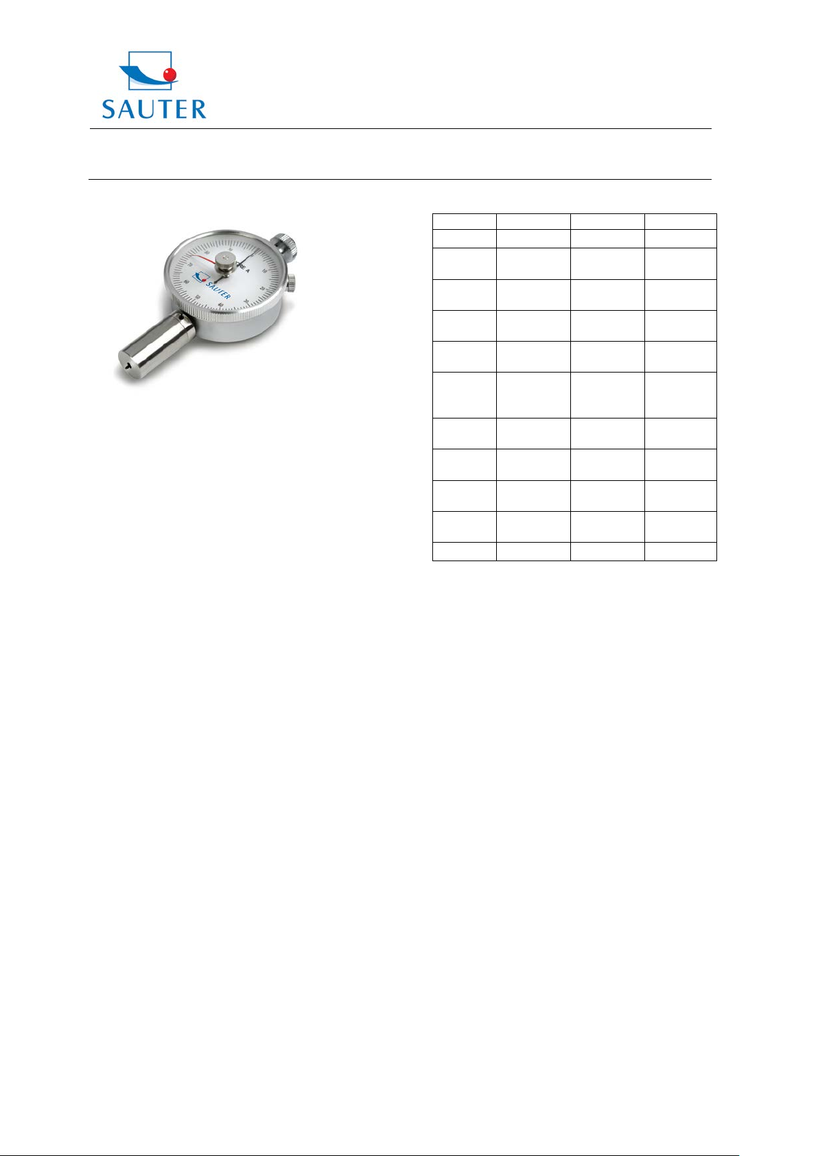
MANUAL SHORE DUROMETER
Ziegelei 1
D-72336 Balingen
E-Mail: info@sauter.eu
2. Specifications
Tip
dentation
Test
pressure
Tel: +49-[0]7433- 9933-199
Fax: +49-[0]7433-9933-149
Internet: www.kern-sohn.com
SR2,5mm
ca.12,5 N 12,5 N 50 N
Shore A
Shore C/ Shore 0
Shore D
Table of contents
1. Features
2. Specifications
3. Method of measurement
4. Maintenance
5. Calibration
1. Features
The hardness of plastics is m ost commonly measured by
the Shore Durometer, using either the Shore A or Shore D
scale. It is the preferred method for measuring rubbers/
elastomers and it’s also used for “softer” plastics s uch as
polyolefins, fluoropolymers and vinyls.
Shore A scale is used for “softer” rubbers, while Shore D
scale is used for “harder” ones.
Shore C/ Shore 0 scale is commonly used for tests with
foam rubbers, sponges or microporous plastics.
Designed in regard to these standards:
• DIN 53505
• ASTM D2240
• ISO 868
spring
force
range
Scale
Diameter
(gross)
Dimensions
3. Method of measurement
Shore Durometer, like many other hardness testers,
measures the depth of indentation in the material created
by a given force on a standardized presser foot. The depth
is dependant on the hardness of the material, its
viscoelastic properties, the shape of the presser foot as
well as the duration of the test. Shore durometers all ow the
measurement of the initial hardness or the indentation
hardness after a given period of time.
The basic test requires applying the force in a constant
manner without shocks, measuring the hardness (depth of
the indentation). If a timed hardness is desired, force is
applied for the required time and then the measurement
result is to be read.
The tested material should have a thickness of minimum
6.4 mm (0.25 inch).
4. Maintenance
After testing the instrument is to be put back in its packing
box. It should not be stored in following environmental
conditions: wet or dusty area, oil or chemicals.
5. Calibration
First the test plate is to be put on a hard and flat base.
The hardness tester is to be located on the test plate by
placing the measurement tip into the hole of the test plate.
The instrument is to be adjusted by turning the external
ring of the round Display to the setpoint of the test plate.
0 – 100
55 mm 55 mm 55 mm
(300g)
26x62x115
(LxBxH) mm
0 – 100
(350g)
26x62x115
(LxBxH) mm
0 – 100
(300g)
26x62x115
(LxBxH) mm
HB&TI-BA-e-1311 1
Page 2
Sauter GmbH
Ziegelei 1
HB & TI
D-72336 Balingen
E-Mail: info@sauter.eu
Instruction Manual
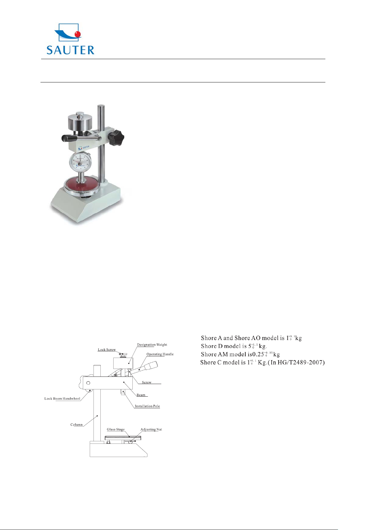
SHORE DUROMETER TEST ST AND
Thank you for buying a SAUTER Durometer Test Stand.
The ruggedness of this stand will allow many years of use
if you will care for an appropriate operation and
maintenance.
If there are any queries, wishes or helpful suggestions, do
not hesitate to call our service number.
Instruction
This Test Stand is produced for our Shore hardness
testers. Combined with this, tests can be made more
stable and accurate. TI-A0 is applied for HB instruments
Shore A and 0; TI-D is applied for HB instruments Shore
D.
Structure
Tel: +49-[0]7433- 9933-199
Fax: +49-[0]7433-9933-149
Internet: www.kern-sohn.com
Operation
The Shore durometer has to be fixed on the test stand by
the installation pole. The hardness testing block has t o be
put onto the glass stage. Then the operating handl e has to
be pressed by poise to place the durometer tip into the
hole of the block until the foot of the durometer touches the
testing block completely. At this time, the hardness value
on the dial should be within ± 1 of the signed value on the
block (side below). If the value is not 100±1, the adjust ing
nut under the glass stage has to be adjus ted to make the
value turn to 100±1.
If the durometer is used without hardness block, the
operating handle also has to be pressed by poise t o place
the durometer tip on the glass stage, touching it
completely. Here, the hardness value on the di al should be
within 100±1. If not, it s hould be adjusted by the adjust ing
nut under the glass stage to make the value turn to 100±1.
The testing material has to be put on the glass stage, the
operation handle has to be moved down by force of the
designation weight. When the durometer touches the test
material completely, the value appears on the dial.
The reading value time of thermoplastic rubber is 15
seconds, vulcanised rubber or other unknown rubbers is 3
seconds. The Shore C model is able to read the value
within 1 second after the durometer has touched the
material completely.
Caution
1. This test stand can only be applied for Shore
durometers. If it is installed with different durometers, the
quality of weight first has to be adjusted according to the
requirements.
GB/T531.1-2008 has a rule for the adjustment of total
quality as shown below:
HB&TI-BA-e-1311 2
Note: Total quality includes quality of lock screws,
designation weight, screw, installation pole and durometer.
2. It has to be applied in environm ent without shock, the
max. pressing speed of the test should not be above
3.2mm/s.
Maintenance
The test stand had to be cleaned after using it with a
smooth cloth to avoid rust.
 Loading...