

Page 1

Sauter GmbH
Ziegelei 1
D-72336 Balingen
E-mail: info@kern-sohn.com
Tel. : +49-[0]7433- 9933-0
Fax: +49-[0]7433-9933-149
Internet: www.sauter.eu
Manual
SAUTER FS
V. 1.0
01/2022
EN
FS-BA-en-2210.docx
Measuring channel CH2
Measuring channel CH1
Interface socket
(optional)
Measuring channel
CH4 (optional)
Measuring channel
CH3 (optional)
Page 2

2 FS-BA-en-2210.docx
EN
SAUTER FS
V. 1.0 01/2022
Manual
Congratulations on your purchase of a digital force gauge with internal or external
measuring cell from SAUTER. We hope you enjoy your quality measuring device with
its wide range of functions. If you have any questions, requests or suggestions, please
do not hesitate to contact us.
Table of contents:
1 Introduction .................................................................................................... 5
2 Check before use ........................................................................................... 5
3 Intended use ................................................................................................... 5
4 Warnings ........................................................................................................ 5
4.1 Transport ................................................................................................................................... 5
4.2 Electrostatic sensitive device ................................................................................................. 5
4.3 Risk of accident ........................................................................................................................ 6
4.4 Damage / defective equipment ................................................................................................ 6
4.5 Accuracy ................................................................................................................................... 6
4.6 Maximum measuring range ..................................................................................................... 7
5 Available models............................................................................................ 7
6 Scope of delivery ........................................................................................... 8
7 Connections ................................................................................................... 8
7.1 USB C socket ............................................................................................................................ 8
7.2 Connection sockets for external sensors .............................................................................. 9
7.2.1 Compatibility and necessary accessories .................................................................................. 9
7.2.2 Plug & play from external sensors .............................................................................................. 9
7.2.3 Pin assignment connector ........................................................................................................ 10
7.3 Expansion from 2 to 4 measuring channels ........................................................................ 10
7.4 Connection socket for optional data interface .................................................................... 10
8 Technical data .............................................................................................. 10
8.1 Battery ..................................................................................................................................... 10
8.2 Display and measurement ..................................................................................................... 11
8.3 Temperature ............................................................................................................................ 11
8.3.1 Storage temperature ................................................................................................................. 11
8.3.2 Use temperature ....................................................................................................................... 11
8.4 Fastening option ..................................................................................................................... 12
Page 3

FS-BA-en-2210.docx 3
9 Prepare measurement ................................................................................. 12
9.1 Switch on ................................................................................................................................. 12
9.2 Activate display with activated energy saving options ...................................................... 12
9.3 Measuring with internal sensor ............................................................................................ 13
9.4 Measuring with external sensors .......................................................................................... 13
9.5 Plugging in and unplugging external sensors .................................................................... 13
10 Measurement ................................................................................................ 13
10.1 Start screen ............................................................................................................................. 13
10.2 Start measurement ................................................................................................................. 14
10.3 Initialise measuring channels ............................................................................................... 14
10.4 Tare measuring channels ...................................................................................................... 14
10.4.1 Channel single ..................................................................................................................... 14
10.4.2 Set all channels to zero (tare) .............................................................................................. 14
10.5 Save measurement data ........................................................................................................ 14
10.6 Force direction ........................................................................................................................ 14
11 Main menu settings ..................................................................................... 15
11.1 Menu unit settings .................................................................................................................. 16
11.1.1 Select language ................................................................................................................... 17
11.1.2 Set time and date ................................................................................................................. 17
11.1.3 Set energy saving options .................................................................................................... 17
11.1.4 Display brightness ................................................................................................................ 17
11.1.5 Switching tones on and off ................................................................................................... 18
11.1.6 Service ................................................................................................................................. 18
11.1.7 Device info............................................................................................................................ 18
11.2 Measurement menu Setting .................................................................................................. 18
11.2.1 Measuring frequency ............................................................................................................ 18
11.2.2 Readability............................................................................................................................ 19
11.2.3 Functions .............................................................................................................................. 20
11.2.4 Channel limits ....................................................................................................................... 21
11.3 Sensor settings ....................................................................................................................... 22
11.3.1 Adjustment ........................................................................................................................... 22
11.3.2 Calibration data .................................................................................................................... 23
11.3.3 Overload values ................................................................................................................... 23
11.4 Internal memory ...................................................................................................................... 24
11.4.1 Composition File name ........................................................................................................ 24
11.4.2 Send file ............................................................................................................................... 24
11.4.3 Delete file ............................................................................................................................. 24
11.4.4 Read out files ....................................................................................................................... 24
12 Switch off the unit ........................................................................................ 24
13 Accessories .................................................................................................. 25
13.1 Standard accessories for force gauges with internal measuring cell .............................. 25
13.2 External measuring cells ....................................................................................................... 25
13.2.1 Adjust and calibrate .............................................................................................................. 26
13.2.2 Additional sensors ................................................................................................................ 26
13.3 Transport case for accessories ............................................................................................ 27
13.4 Read out stored measured values with EXCEL plug-in ..................................................... 27
Page 4

4 FS-BA-en-2210.docx
14 Power supply ............................................................................................... 27
14.1 Charging the battery .............................................................................................................. 27
14.2 Plug-in power supply unit ..................................................................................................... 28
14.3 Power supply via PC .............................................................................................................. 28
15 Interface ........................................................................................................ 28
15.1 Interface description .............................................................................................................. 28
15.1.1 USB ...................................................................................................................................... 28
15.2 Interface protocol ................................................................................................................... 28
16 Declaration of conformity ........................................................................... 28
Page 5

FS-BA-en-2210.docx 5
1 Introduction
Read these operating instructions carefully before commissioning, even if you already
have experience with SAUTER measuring devices.
SAUTER offers the software and accessories as an option to make the measuring
device more versatile in use. Please enquire with SAUTER or your SAUTER dealer or
visit our website at www.sauter.eu.
2 Check before use
After receiving the unit, check in advance whether there has been any transport
damage, whether the outer packaging, the plastic housing, other parts or even the unit
itself has been damaged. If any damage is apparent, please notify the specialist dealer
or manufacturer immediately.
3 Intended use
The SAUTER FS device is intended for measuring forces and torques in industrial
environments.
4 Warnings
4.1 Transport
A lithium-ion battery is built into the unit. The technical data of the battery is described
in chapter 8.1 is described. Observe the national and international transport regulations
for devices with a permanently installed lithium-ion battery.
4.2 Electrostatic sensitive device
The unit can be destroyed by electrostatic discharges. Connectors for
HF signals are particularly at risk. Please observe the handling
instructions for electrostatically sensitive components.
Page 6
6 FS-BA-en-2210.docx
4.3 Risk of accident
Observe the national accident prevention regulations. Incorrect use of the
equipment can lead to serious injuries, death, property damage and personal
injury. Use may only be carried out by trained and experienced personnel.
Never load load cells and force gauges beyond the Emax range (nominal load, max.
capacity) of the sensor used. Overloaded load cells no longer have the required
accuracy. Overloaded or deformed load cells must not be used any longer and must
be replaced immediately. Never step under suspended loads. Always fit overload or
breakage protection devices to your system. Always observe the permissible static and
dynamic loads of the accessories you are using.
Check measuring cells regularly for deformations and cracks.
Shocks, vibrations and torsion on the force application bolt can damage the sensor!
Only transport the unit in the transport case supplied!
4.4 Damage / defective equipment
Do not use damaged measuring instruments, cables, plug-in power supplies or similar!
Contact the service department of the dealer or manufacturer.
Do not ship units with defective batteries! Pack devices with defective
batteries in suitable fireproof containers. Contact the service department of
the specialist dealer or manufacturer.
4.5 Accuracy
Have force gauges and load cells calibrated at regular intervals. Load the load cell only
in its specified load direction. Avoid transverse forces. For load cells with a 4-wire
connection, the characteristic value changes when the cable supplied is shortened or
lengthened.
Page 7

FS-BA-en-2210.docx 7
4.6 Maximum measuring range
Never load the unit beyond the maximum measuring range! The max.
measuring range of your unit with internal measuring cell can be found on the
type plate on the back of the unit! The maximum measuring range of external
sensors can be found on the type plate on the sensors!
Overloads are signalled by a warning tone when the signal tones are activated.
Overload values are stored. Overloaded units and sensors are excluded from warranty,
return and exchange.
5 Available models
Model
internal
measuring
cell
Measuring
range
internal
measuring
cell [Max] N
Readability
internal
measuring
cell N
Number of
measuring
channels
Max.
possible
resolution
per channel
d
FS 2 - - - 2
10.000
FS 2-20
-
20
0,004
2
10.000
FS 2-50
-
50
0,01
2
10.000
FS 2-100
-
100
0,02
2
10.000
FS 2-200
-
200
0,04
2
10.000
FS 2-500
-
500
0,1
2
10.000
FS 4 - - - 4
10.000
FS 4-20
-
20
0,004
4
10.000
FS 4-50
-
50
0,01
4
10.000
FS 4-100
-
100
0,02
4
10.000
FS 4-200
-
200
0,04
4
10.000
FS 4-500
-
500
0,1
4
10.000
Page 8
8 FS-BA-en-2210.docx
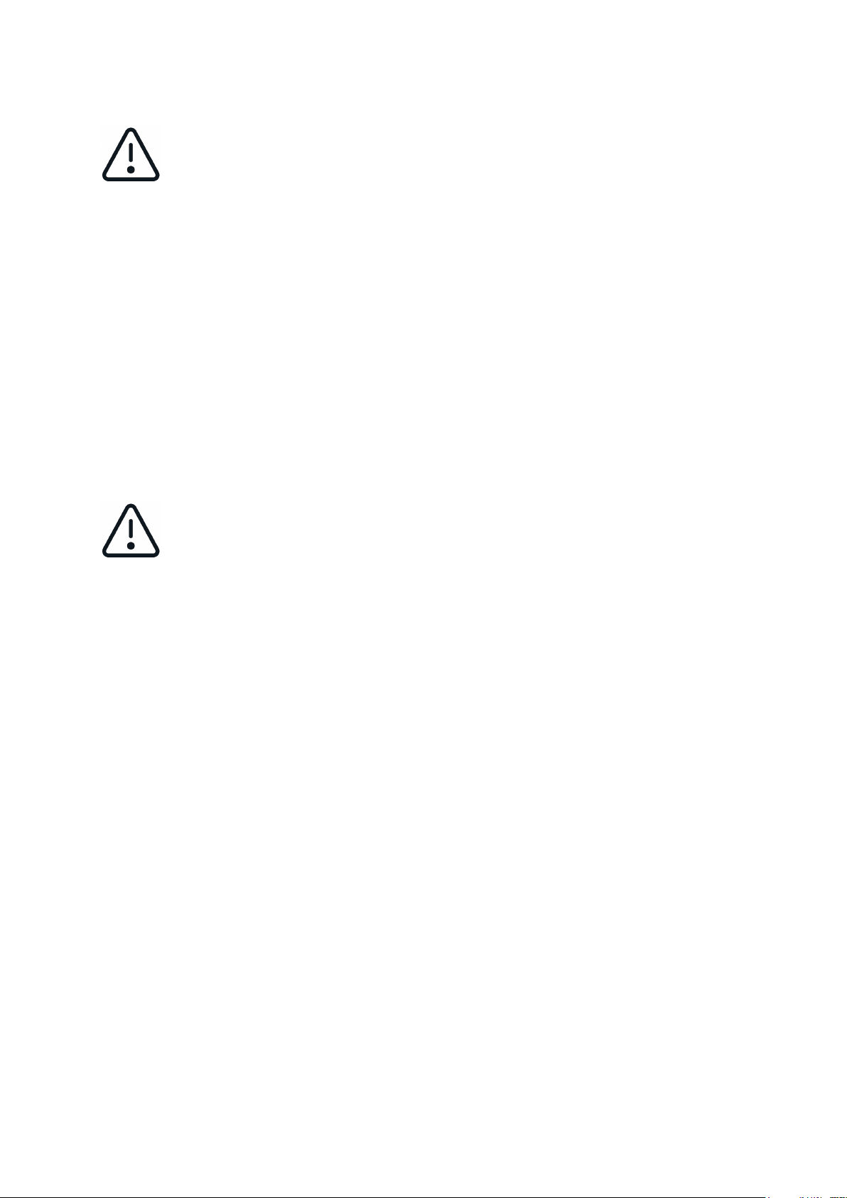
6 Scope of delivery
- Force gauge FS
- Transport case Systainer®
- Touch-Pen
- USB C cable
- EU plug-in power supply unit
- Operating instructions
7 Connections
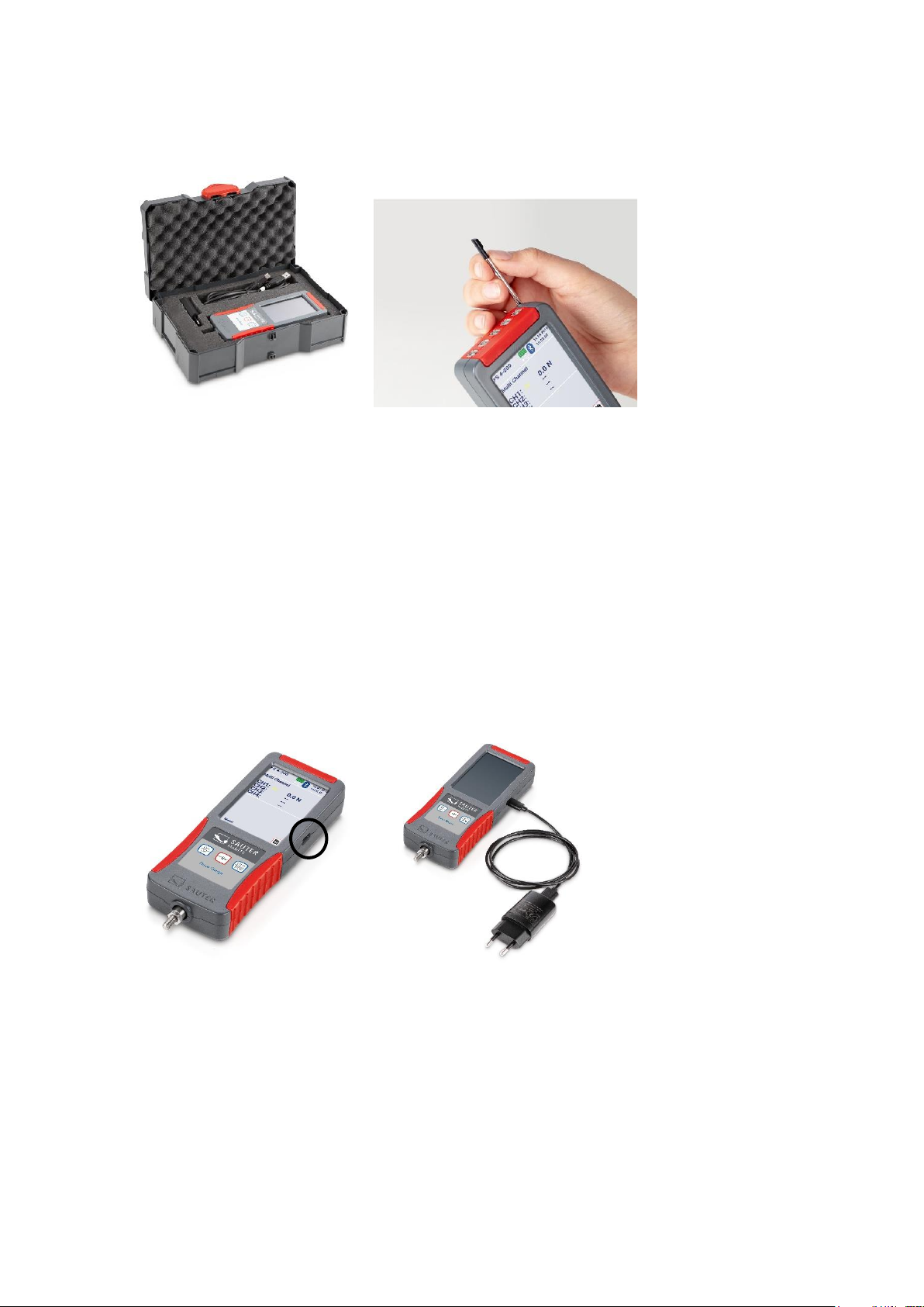
7.1 USB C socket
Your unit is supplied with power via the USB C socket on the right-hand side of the unit
and serves as an interface for data transfer to a PC. The interface description can be
found in chapter 15 Interface chapter.
USB-C
Page 9

FS-BA-en-2210.docx 9
7.2 Connection sockets for external sensors
Depending on the model, 2 or 4 strain gauge sensors can be connected to your force
gauge and measured simultaneously. There are always 5 sockets on your device. The
measuring channels 3 and 4 and the interface socket are only optionally assigned!
You will receive the connectors when you order a sensor from SAUTER, as described
in section 13.2 "" described.
7.2.1 Compatibility and necessary accessories
It is recommended to purchase the sensors directly from SAUTER. There you will
receive compatible sensors with the corresponding necessary services. The services
listed in chapter 13.2 include the adjustment of the measuring chain, the connector and
the required data memory chip.
7.2.2 Plug & play from external sensors
External sensors can be unplugged and replaced by other adjusted sensors. Due to
the tolerances of the respective input channels, the sensors must be adjusted with the
device used. For this purpose, the unit must be sent to the KERN laboratory when
sensors are reordered.
If possible, always connect the sensor to the channel on which it was
adjusted and calibrated. It is best to keep a record of this! This will give you
the highest possible accuracy.
Measuring channel CH2
Measuring channel CH1
Interface socket
(optional)
Measuring channel
CH4 (optional)
Measuring channel
CH3 (optional)
Page 10

10 FS-BA-en-2210.docx
7.2.3 Pin assignment connector
7.3 Expansion from 2 to 4 measuring channels
Each unit is factory-equipped with sockets for 4 measuring channels, even if you have
purchased a variant with 2 channels.
7.4 Connection socket for optional data interface
The socket is available on the unit! Interface currently not available.
8 Technical data
8.1 Battery
- Lithium-ion rechargeable battery
- Nominal voltage 3.7V
- Capacity 2400mAh or 8.88Wh
Safety data sheets are available in the manufacturer's webshop or on
request! Do not use devices with defective batteries! Do not send defective
batteries or devices with defective batteries!
Pin
Connection
1
N.C.
2
Memory chip IO
3
Memory chip GND
4
N.C.
5
N.C.
6
Supply +
7
Input +
8
Input -
9
Supply +
10
N.C.
Page 11

FS-BA-en-2210.docx 11
8.2 Display and measurement
- 3.5" touch screen
- Standard version with 2 or 4 measuring channels for external force sensors
(subsequently expandable from 2 to 4)
- An internal measuring cell is possible (will be deactivated if slot 1 has a
external measuring cell is plugged in)
- Suitable for 4-wire and 6-wire sensors with strain gauges up to 3mV/V
- Bridge supply voltage 6V
- High resolution: up to 10000 points per measuring channel
- Internal measuring frequency: 1000 Hz per measuring channel
- Measurement accuracy:
o with internal measuring cell: 0.1 % of [Max].
o with external measuring cell: among other things, from the measuring
cells used
- Overall dimensions W×D×H 71×31×180 mm
- Overload protection: 150 % of [Max] with internal measuring cell
- Thread on load receptor: M6 (external)
- Internal battery operation, standard, operating time up to 8 h, charging time
approx. 8 h
- External mains adapter, for connection to the USB-C socket, as standard
- Net weight approx. 0.4 kg
- Protection class IP40
8.3 Temperature
8.3.1 Storage temperature
-10°C to 40°C
Recommended storage temperature for lithium-ion battery: +10°C to 20°C
8.3.2 Use temperature
10°C to 40°C
In this range the measuring system is temperature compensated.
Page 12

12 FS-BA-en-2210.docx
8.4 Fastening option
The unit can be attached to test stands, fixtures and handholds (AFK 02 is available
as an option) using M3 screws at the four threaded holes on the rear:
9 Prepare measurement
9.1 Switch on
Press and hold the ON/OFF button for approx. 3 sec.
9.2 Activate display with activated energy saving options
If you have activated the energy-saving mode of the display as described in section
11.1.3 it is possible that your unit is switched on and only the display is switched off.
To activate the display, briefly press the START/STOP key or touch the display. If the
display cannot be activated, start the machine as described in section 9.1 described.
Page 13

FS-BA-en-2210.docx 13
9.3 Measuring with internal sensor
For units equipped with an internal sensor (not FS 2 and FS 4), the internal sensor is
displayed as channel 0 (CH0) when you click on the "Measurement" function. If an
external sensor is connected, CH0 is automatically deactivated and the external
channels are displayed instead.
9.4 Measuring with external sensors
The external measuring channels are displayed as CH1 and CH2 for FS 2-x and CH1
to CH4 for FS 4-x. On the external channels CH1 to CH4 it is possible to measure and
save the data simultaneously.
9.5 Plugging in and unplugging external sensors
To plug in or unplug the external sensors, the meter must be switched off or must be
in the main menu, press briefly. The start screen appears and you are in the main
menu.
10 Measurement
10.1 Start screen
Menu
Measurement
Page 14

14 FS-BA-en-2210.docx
10.2 Start measurement
Click on Measurement on the touch screen
10.3 Initialise measuring channels
Press the START/STOP button to display the measured values of the connected
sensors.
10.4 Tare measuring channels
10.4.1 Channel single
To set a single channel to zero, click with the touch pen on →0"" to the right of the
displayed channel.
10.4.2 Set all channels to zero (tare)
Press and hold the button for at least →03 seconds to set all connected sensors to
0.
10.5 Save measurement data
The different measuring functions that you can use and how the measured values are
stored is described in section 11.2.3
10.6 Force direction
Units with internal sensor can measure forces in tension direction (positive measured
value) and in compression direction (negative measured value). External sensors can
differ. You can use sensors for tensile and compressive force or tensile force sensors
or compressive force sensors. For more information on external sensors, see chapter
13.2 External measuring cells.
Page 15

FS-BA-en-2210.docx 15
The forces on the FS encoder must always be applied in the axial direction of the load
application bolt. Avoid transverse forces. These cause measurement errors and can
damage the sensor.
Ideal force application
Incorrect force application
11 Main menu settings
When your device is in the start menu, you can make settings by clicking on "Menu".
This will take you to the main menu with the following sub-pages:
wrong
wrong
wrong
ideal
ideal
ideal
Page 16

16 FS-BA-en-2210.docx
Clicking on or takes you to the previous page. Press the ON / OFF button to
return to the start screen.
11.1 Menu unit settings
Device settings
Measurement settings
Sensor settings
Internal memory
Main menu
Device
Language
Service
Unit information
Display
Audio
Page 17

FS-BA-en-2210.docx 17
11.1.1 Select language
Select your desired language:
Menu Device settings→ Language→
11.1.2 Set time and date
Menu Machine Settings→ Date →/ Time
Click on "Change" with the touch pen and set the current time and date with the arrows.
Save the entered values by clicking on "OK".
11.1.3 Set energy saving options
Menu Machine Settings→ Energy→ Saving Options
Set here when the unit or display should switch off to save energy! Switching off the
display is only recommended for long-term measurements! As a rule, never switch off
the unit and display.
To reactivate the display, briefly press the START/STOP button or touch the display.
11.1.4 Display brightness
Menu Device settings→ Display→
Set the desired brightness of the display by pressing the slider on the display.
Page 18

18 FS-BA-en-2210.docx
11.1.5 Switching tones on and off
Menu Unit→ settings Switch tones→ on and off
11.1.6 Service
Menu Unit Settings→ Service→
11.1.6.1 Display raw data
Switch here to display the raw measured values during adjustment as AD value or as
voltage in mV.
11.1.6.2 Reset unit
Do not use this function! Contact the service department!
11.1.7 Device info
Menu Device Settings→ Device Info→
Here they receive information about
- Device name or model
- Installed firmware revision
- Serial number of the unit
11.2 Measurement menu Setting
11.2.1 Measuring frequency
11.2.1.1 Setting
By clicking on change, you can change the frequency with which the measured values
are stored in the "Track" mode or transmitted to the interface! The following frequencies
are possible: 1000, 500, 100, 50, 10, 5 and 1 Hz.
11.2.1.2 What frequency is needed?
Choose the frequency as low as possible and as high as necessary! High frequency
data storage or transmission causes a large amount of data which takes a long time to
transmit.
11.2.1.2.1 For long-term measurements
such as a fatigue test, select a very low frequency, max. 50Hz.
Page 19

FS-BA-en-2210.docx 19
11.2.1.2.2 For short time measurements
Such as maximum load measurement to destruction, which lasts only a few seconds
choose a higher frequency.
11.2.2 Readability
By clicking on change you can increase the readability by the displayed factor. The
maximum resolution is n=10,000
The smallest adjustable readability for a sensor is calculated as follows:
Example FS 2-100:
Set the readability factor as high as possible and as low as necessary! Very low
readability often leads to unstable display values with the measuring technology used
and the high sampling frequencies. Readability factor 1 should only be set if the
measured data is subsequently processed with additional PC programs, for example
to filter, smooth, etc. the stored values.
If values are only read or stored manually, it is recommended to set the readability
factor ≥ 5.
Page 20

20 FS-BA-en-2210.docx
11.2.3 Functions
11.2.3.1 Track
Measured values are displayed continuously and stored with the set sampling
frequency if required.
To save the readings:
1. Press the Start/Stop button
2. The measured values are now saved and the generated file name in which the
data are saved appears in the display under the "Recording in progress"
indicator.
3. Pressing the Start/Stop key briefly stops the storage of the measurement series,
"Recording paused" appears in the display.
4. Pressing briefly again continues the recording. Recording in progress" is
displayed
5. Press the Start/Stop button for more than 3 seconds to end the recording in the
displayed file. Recording finished" display
6. To save a new measurement series in a new file, proceed again as in point 1.
11.2.3.2 Peak
To detect a peak value, select the Peak setting. When the measured value is shown
in the display, start the detection by briefly pressing the START/STOP button.
Please note that a peak can only be detected above the threshold value of +/- 5% of
the nominal measured value. For example 100N measuring range: Peak detection
from +5N or -5N.
The message "Peak running" appears in the display. Carry out your measurement. If
a peak value is reached and then falls again, the measurement is ended. You can now
see the file name of the measurement in the display and transfer it to your
measurement protocol.
Page 21

FS-BA-en-2210.docx 21
11.2.3.3 Manual without statistics
Use this mode to manually save the measured values currently displayed after
initialisation at the touch of a button.
1. Press the START/STOP button. The display shows "Manual running". This
value is not yet saved.
2. Each additional short press of the START/STOP button saves the currently
displayed readings. The number of stored values is displayed at the bottom
right. To the left is the file name in which the data is saved.
3. Press and hold START/STOP until the display shows "Manually ended" to end
the measurement series. No further points can be saved in this file.
4. By pressing the START/STOP button again, the mode starts from the beginning
and a new file is created.
11.2.3.4 Manual with statistics
The manual storage of the measured values is the same as described in chapter
11.2.3.3 described.
In addition, the min, max and average values of the stored measured values are
displayed here.
11.2.4 Channel limits
This setting controls the traffic light displayed when you are working in the
Measurement window. Change the values by clicking on them with the touch pen.
If the function is not required, enter the negative value of the sensor as MIN and the
positive value as MAX. The traffic light remains permanently yellow.
11.2.4.1 Yellow
Displayed measured value is below the entered value MIN
11.2.4.2 Green
Displayed value is between the entered values MIN and MAX
11.2.4.3 Red
Displayed measured value is above the entered value MAX
Page 22

22 FS-BA-en-2210.docx
11.3 Sensor settings
Select the channel on which you want to make settings. Only external channels to
which a sensor is connected are displayed. Only use the plugs with memory chip fitted
by SAUTER for external sensors.
Force gauges and optional external sensors, as described in chapter 13.2 are
delivered adjusted. Only make adjustments on this page if your device no longer
displays the correct (and checked) measured values and you have experience with the
adjustment of force measuring devices. Calibrated measuring instruments must be
recalibrated after an adjustment.
11.3.1 Adjustment
To recalibrate a device, you need a calibration weight. Ideally with the nominal load of
the sensor to be adjusted.
11.3.1.1 Measuring range and unit
Do not change these values. A new adjustment and possibly also a recalibration will
be necessary!
11.3.1.2 Readability
The displayed value is the smallest adjustable readability. Set the readability required
for your application 11.2.2 chapter, set the readability required for your application
before using the meter.
11.3.1.3 Two-point adjustment
Click on Adjustment and then on Two-Point Adjustment.
11.3.1.3.1 Enter the values of the calibration weights
Enter your adjustment points in the upper part of the display at "Value? For example:
- Positive adjustment point: 500N
- Negative adjustment point: 0N
It is recommended to adjust with a weight that is close to the nominal value. For
example, a weight of 400N to 500N for a force gauge with a maximum measuring range
of 500N. Too small adjustment weights lead to a high measuring error!
Page 23

FS-BA-en-2210.docx 23
11.3.1.3.2 Load and unload before adjustment
Load and unload the unit at least 3 times with the nominal load.
11.3.1.3.3 Read in adjustment points
Now read in the adjustment 11.3.1.3.1 adjustment points. When you have attached the
respective adjustment weight, click on positive adjustment point and negative
adjustment point in the lower area of the display. After successful recording, the raw
values are displayed to the right with a tick next to them.
11.3.1.3.4 Save adjustment
Save the adjustment by clicking on Save. When the adjustment has been successfully
saved, a tick symbol appears to the right of it.
11.3.1.3.5 Check adjustment
Check with your adjustment weights whether the settings you have made are correct.
Proceed as described in chapter 10 described.
11.3.2 Calibration data
On this page you will find information if a measuring device with internal cell (CH0) or
a device with external measuring cell (CH1 to CH4) has been calibrated in the KERN
laboratory.
The specified measuring channel indicates to which channel (CH1 to CH4) an external
sensor was connected during adjustment and calibration. It is recommended to always
use external sensors on the same channel and on the same measuring device on
which it was also adjusted and calibrated in order to keep the measurement error to a
minimum.
The calibration date indicates the last calibration. Under Certificate, enter the number
of the calibration to be able to assign the corresponding certificate.
11.3.3 Overload values
On this page you can see the three highest overload values, if there were overloads
above the nominal load. Avoid overloads! They lead to measurement inaccuracies, can
damage the sensor and void the warranty on your unit!
Page 24

24 FS-BA-en-2210.docx
11.4 Internal memory
11.4.1 Composition File name
f_ddMMyy_hhmmss
f: stored measuring function
M= Measuring function manual
T= Mandatory function Track
P= measuring function peak
The remaining file name is composed of the date and time at which the file was created.
11.4.2 Send file
If you connect the measuring instrument to a PC via an interface, you can send the
selected files to the PC. The optionally available plug-in for MS Excel SAUTER AFI 2.0
is recommended for this purpose.
11.4.3 Delete file
Select the files you no longer need to delete them. Do not collect data on the device.
Transfer them to another storage medium as soon as possible and delete the entire
data memory of the FS!
11.4.4 Read out files
Reading out files with a PC is not possible. The PC must be set to receive at the
interface to be able to receive the files sent by the FS.
12 Switch off the unit
Press and hold the ON/OFF button until the unit switches off.
Page 25

FS-BA-en-2210.docx 25
13 Accessories
When attaching accessories to your sensor, please note that the dead weight
of the accessories must be taken into account!
13.1 Standard accessories for force gauges with internal
measuring cell
• AC 43 Standard Attachments Metal
• AE 01 Standard clamp Clamping range from 0 to 7 mm, 0 to 500 N
• AE 02 Wide jaw clamp Clamping range from 0 to 6 mm, 0 to 500 N
• AE 03 Strap tension clamp Clamping width from 0 to 2.5 mm, 0 to 500 N
• AE 04 Strap tension clamp Clamping width from 0 to 6 mm, 0 to 500 N
• AE 05 Rope and thread tension clamp 0 to 500 N
• AE 06 Cable pull-off clamp Clamping width 1.5 to 6 mm, 0 to 500 N
• AE 07 Wedge clamp Clamping width 0 to 6 mm, 0 to 500 N
• AE 2K screw clamp Clamping width 0 to 15 mm, 0 to 2000 N
• AE 500 Screw clamp Clamping range from 0 to 10 mm, 0 to 500 N
• AFK 02 Holder for force gauges
Further accessories can be found in the webshop www.sauter.eu
13.2 External measuring cells
External sensors are available in the webshop www.sauter.eu. For each sensor you
need the service corresponding to the nominal load from the following table, incl.
connector and memory chip:
Page 26

26 FS-BA-en-2210.docx
FS 402
Connector for FS incl. PARAMETER MEMORY mounted on measuring cell and
two-point adjusted with weight up to 0.5kN
FS 403
Connector for FS incl. PARAMETER MEMORY mounted on measuring cell and
two-point adjusted with weight up to 2kN
FS 404
Connector for FS incl. PARAMETER MEMORY mounted on measuring cell and
two-point adjusted with weight up to 5kN
FS 405
Connector for FS incl. PARAMETER MEMORY mounted on measuring cell and
two-point adjusted with weight up to 20kN
FS 406
Connector for FS incl. PARAMETER MEMORY mounted on measuring cell and
two-point adjusted with weight up to 50kN
FS 407
Connector for FS incl. PARAMETER MEMORY mounted on measuring cell and
two-point adjusted with weight up to 120kN
FS 408
Connector for FS incl. PARAMETER MEMORY mounted on measuring cell and
two-point adjusted with weight up to 250kN
13.2.1 Adjust and calibrate
In order to adjust and calibrate the entire measuring chain, a measuring
device and sensor are required in the core laboratory! Your QM
representative can provide you with information on the period in which
recalibration is necessary. In any case, we recommend a DAkks calibration certificate
for every new device and sensor.
13.2.2 Additional sensors
If you purchase sensors for your device at a later date, it is necessary to send the
device to the KERN laboratory, as the entire measuring chain is required for adjustment
and calibration.
Check which other sensors in your range currently need recalibration or will need it in
the foreseeable future and send them together to the KERN laboratory to minimise
freight costs and downtime. Observe the national and international transport
regulations for devices with permanently installed lithium-ion batteries.
Page 27

FS-BA-en-2210.docx 27
13.3 Transport case for accessories
For the transport and storage of external sensors, accessories and tools, the transport
case for accessories is available with the article designation FS TKZ. The transport
case for the force gauge included in the scope of delivery can be connected to several
other cases via the "T-LOCK" fastener.
13.4 Read out stored measured values with EXCEL plug-in
With the optionally available EXCEL plug-in SAUTER AFI 2.0, stored measurement
data can be transferred to a PC. (EXCEL software not included in delivery!)
14 Power supply
14.1 Charging the battery
The device is equipped with a rechargeable battery at the factory. Charge the battery
using the supplied USB-C cable and a power source with the following values:
- Voltage: 5V DC
- Current: 1A
If a power source and USB cable have been connected correctly, the plug symbol
appears in the display to the right of the battery charge status when the unit is switched
on.
Page 28

28 FS-BA-en-2210.docx
14.2 Plug-in power supply unit
In some countries, a different plug-in power supply unit may be required for connection
to the local mains supply. The adapter or plug-in power supply used must not exceed
the output values at the USB output:
- Voltage: 5V DC
- Current: 1A
Do not use a defective or damaged plug-in power supply! There is a danger
to life due to high voltage!
14.3 Power supply via PC
The unit can also be powered from a PC using a USB C cable to simultaneously
transfer data via the USB interface.
15 Interface
15.1 Interface description
15.1.1 USB
This is a virtual USB interface. The device is not recognised as a storage medium!
Baud rate: 115200 Databits: 8 Stopbits:1 Parity: none
15.2 Interface protocol
The interface protocol KCP (KERN Communication Protocol) can be downloaded from
the website www.kern-sohn.com.
Important ASCII interface commands:
- SI Sends the current reading immediately without waiting for stable
conditions.
- SIR Send current display immediately and repeat
- U Query of the display unit
- ZI immediately zero
- @ cancel / unsubscribe
16 Declaration of conformity
To view the CE Declaration, please click on the following link:
https://www.kern-sohn.com/shop/de/DOWNLOADS/
 Loading...