

KERN & Sohn GmbH
Ziegelei 1
D-72336 Balingen
E-Mail: info@kern-sohn.com
Tel: +49-[0]7433- 9933-0
Fax: +49-[0]7433-9933-149
Internet: www.kern-sohn.com
User instructions
Polarisation microscope
KERN OPE-1
OPE 118
Version 1.0
01/2016
OPE-1-BA-e-1610


GB
KERN OBE-1
Version 1.0 01/2016
User instructions
Transmitted light microscope
Table of contents
1 Before use .................................................................................... 3
1.1 General notes ............................................................................................................................ 3
1.2 Notes on the electrical system ................................................................................................ 3
1.3 Storage ...................................................................................................................................... 4
1.4 Maintenance and cleaning ....................................................................................................... 5
2 Nomenclature ............................................................................... 6
3 Technical data / Features ............................................................ 7
4 Assembly ...................................................................................... 9
4.1 Polarisation unit + Microscope head ...................................................................................... 9
4.2 Objectives ................................................................................................................................. 9
4.3 Eyepieces .................................................................................................................................. 9
4.4 Colour filter ............................................................................................................................. 10
4.5 Condenser + Polariser ........................................................................................................... 10
5 Operation .................................................................................... 10
5.1 Getting started ........................................................................................................................ 10
5.2 (Pre-) focussing ...................................................................................................................... 11
5.3 Centre-adjusting the stage .................................................................................................... 12
5.4 Adjusting the magnification .................................................................................................. 14
5.5 Adjusting the illumination ..................................................................................................... 15
5.6 Adjusting the polarisation unit ............................................................................................. 16
6 Changing the bulb ..................................................................... 17
7 Changing the fuse ...................................................................... 17
8 Trouble shooting ........................................................................ 18
9 Service ........................................................................................ 20
10 Disposal ...................................................................................... 20
11 Further information .................................................................... 20
OPE-1-BA-e-1610 2

1 Before use
1.1 General notes
You must open the packaging carefully, to make sure that none of the accessories in
the packaging fall on the floor and get broken.
In general, microscopes should always be handled carefully because they are
sensitive precision instruments. When using or transporting the microscope it is
particularly important to avoid abrupt movements, as this may damage the optical
components.
You should also avoid getting dirt or finger prints on the lens surface, because in
most cases this will reduce image clarity.
To maintain the performance of the microscope, it must never be disassembled. So
components such as lenses and other optical elements should be left as they were
before use. Also the electrical parts on the rear and base of the device must not be
tampered with, as in this area there is an additional risk of triggering an electric
shock.
1.2 Notes on the electrical system
Before connecting to a mains power supply, you must make sure that you are using
the correct input voltage. The information to select the correct mains cable is located
on the device, on the rear of the product directly above the connection socket. You
must comply with this information. If you do not comply with these specifications, then
fires or other damage to the device could occur.
The main switch must also be switched off before the mains cable is connected. In
this way you will avoid triggering an electric shock.
If you are using an extension cable, then the mains cable you use must be earthed.
If the original fuse should blow, it must only be replaced by an appropriate fuse.
Suitable replacement fuses are included with the delivery.
When carrying out any procedures whereby you come into contact with the electrical
system of the device, such as, for example, changing the bulb or fuse, only carry out
these procedures when the power is disconnected.
3 OPE-1-BA-e-1610

1.3 Storage
You should ensure that the device is not exposed to direct sunlight, temperatures
which are too high or too low, vibrations, dust or a high level of humidity.
The ideal temperature range is between 0 and 40°C and a relative humidity of 85%
should not be exceeded.
The device should always be located on a rigid, smooth, horizontal surface.
When the microscope is not being used, you should cover it with the enclosed dust
protective cover. When doing this, the power supply is stopped by switching off at the
main switch and unplugging the mains cable. If the eyepieces are being stored
separately, the protective caps must be fitted to the tube connectors. In most cases,
if dust and dirt gets inside the optical unit of a microscope this can cause irreversible
errors or damage.
The best way to store accessories which consist of optical elements, such as, for
example, eyepieces and objectives, is in a dry box with desiccant.
OPE-1-BA-e-1610 4

1.4 Maintenance and cleaning
In any event, the device must be kept clean and dusted regularly.
If any moisture should be occur, before you wipe down the device you must ensure
that the mains power is switched off.
When glass components become dirty, the best way to clean them is to wipe them
gently with a lint-free cloth.
To wipe oil stains or finger prints off the lens surface, moisten the lint free cloth with a
mixture of ether and alcohol (70 / 30 ratio) and use this to clean the lens.
You must be careful when handling ether and alcohol, as these are highly flammable
substances. You must therefore keep it away from naked flames and electrical
devices which can be switched on and off, and only use it in well-ventilated rooms.
However organic solutions of this type should not be used to clean other components
of the device. This could lead to damage to the paint finish. To do this, it is sufficient
to use a neutral cleaning product.
You could also use the following cleaning products to clean the optical components:
Special cleaner for optical lenses
Special optical cleaning cloths
Bellows
Brush
When handled correctly and checked regularly, the microscope should give many
years of efficient service.
Should repairs still be necessary, please contact your KERN dealer or our Technical
Department.
5 OPE-1-BA-e-1610
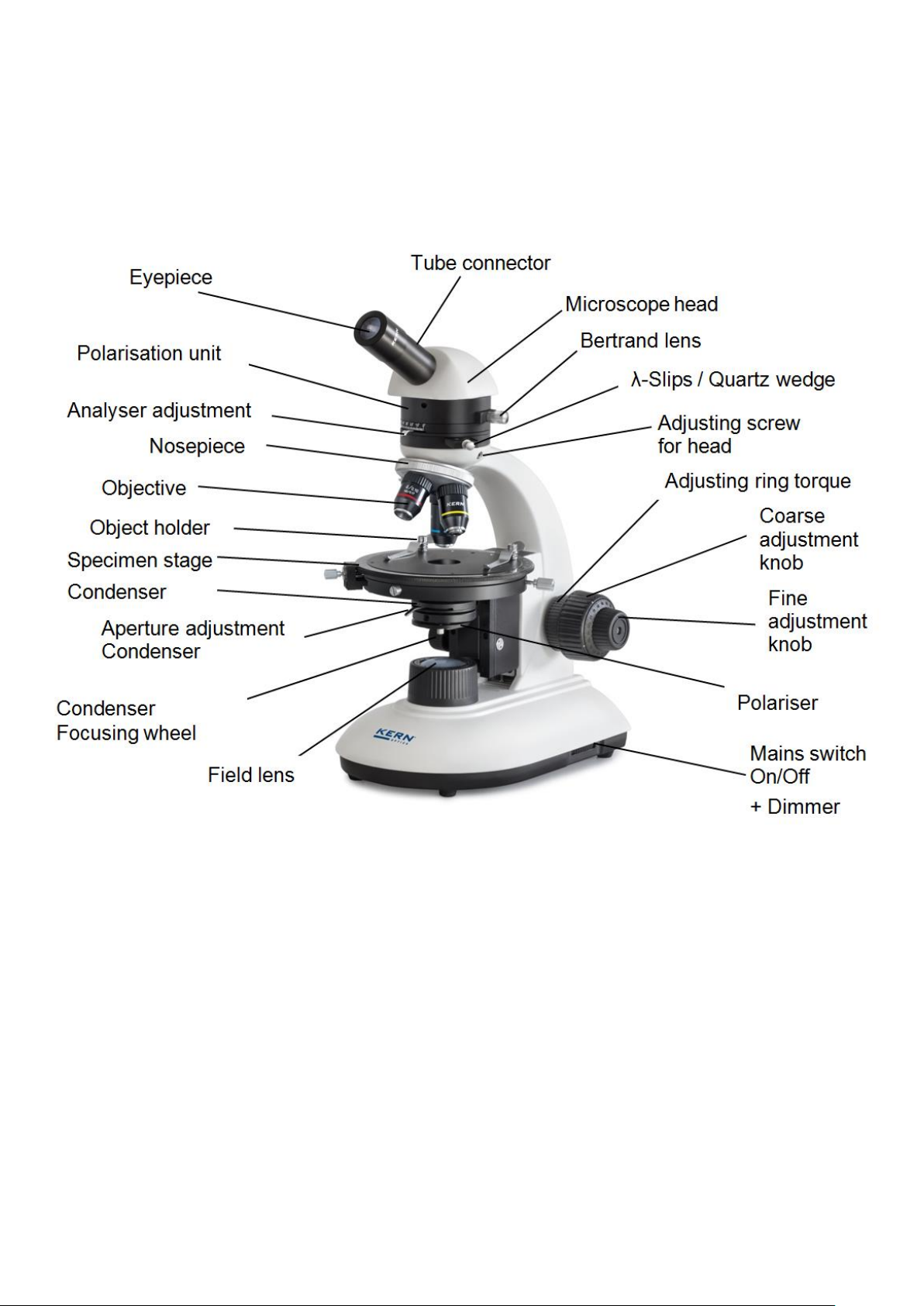
2 Nomenclature
OPE-1-BA-e-1610 6

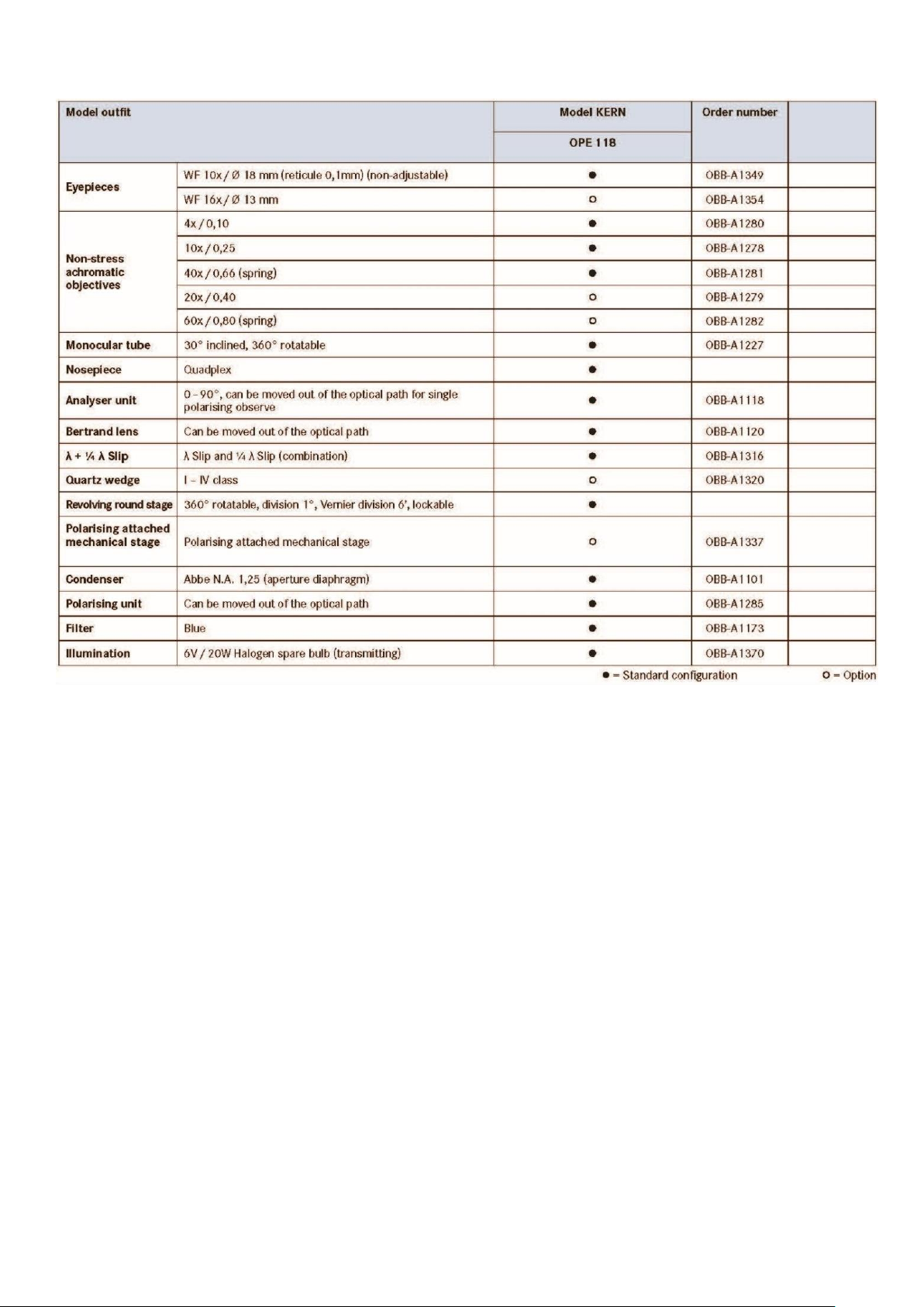
3 Technical data / Features
Model
KERN
Standard configuration
Optical
system
Tube
Eye pieces
Objectives
Illumination
OPE 118
Finite
Monocular
WF 10x / Ø 18 mm
Achromatic
4x/10x/40x
6V / 20W Halogen (Transmitted)
Product dimensions:
360x200x400 mm
Packaging dimensions:
440x340x240 mm
Net weight:
5,5 kg
Gross weight:
6 kg
Input voltage:
AC 100-240V, 50-60Hz
Output voltage:
DC 1,2-6V
Fuse:
2A 5x20mm
7 OPE-1-BA-e-1610
OPE-1-BA-e-1610 8

4 Assembly
4.1 Polarisation unit + Microscope head
Inside the packaging the microscope head is already mounted but inclined towards
the rear. At first it must be removed by loosening the fixing screw on the connection
point of the tube and then taking it off from the connection point.
Instead of the head now the polarisation unit can be attached and fixed by the fixing
screw.
Thereby the unit can only be aligned in a certain position.
This ensures a pin, attached on the bottom side of the unit. This pin needs to be
inserted into the according socket on the rear of the connection point.
After that, the head is fitted onto the top of the connection point of the polarisation
unit and fixed by three fixing screws.
Preferably the head needs to be aligned in a way of pointing centrally towards the
front.
You should always make sure that you do not touch the lenses with your bare fingers
and that no dust enters the apertures.
The Bertrand lens and the analyser are inherent parts of the polarization unit. The
Lambda slip however, needs to be mounted additionally.
Please also see section 5.6 Adjusting the polarization unit.
4.2 Objectives
All three objectives are already mounted to the nosepiece. After removing the
protective foil they are ready for use. They are ranged in such a way that if you turn
the nosepiece clockwise, the objective with the next higher magnification appears.
When the objectives need to be dismounted, you should always make sure that you
do not touch the lenses with your bare fingers and that no dust enters the apertures.
4.3 Eyepieces
The eyepiece is simply placed onto the tube connectors, when the protective cover is
removed before. There is no possibility of fixating the eyepiece. You should always
make sure that you do not touch the lenses with your bare fingers and that no dust
enters the apertures.
9 OPE-1-BA-e-1610

4.4 Colour filter
Standardly the microscopes of the OPE-1 series are equipped with a blue colour
filter. This filter is firmly connected to a holding ring an you can simply put it onto the
housing of the field lens in case of usage.
4.5 Condenser + Polariser
The condenser is firmly fixed onto a holding ring (condenser holder) underneath the
microscope stage. The lever for the aperture diaphragm is directed towards the front.
There is the ability to adjust the height of the condenser, but not to centre it.
Right beneath the condenser the polariser is attached. According to the application
requirements it can be swung in or out of the beam path.
We recommend that you use the course adjustment knob to bring the specimen
stage to its uppermost position when you need to remove the condenser. Then use
the focus dial of the condenser to move the condenser holder to a low position. In
this way the condenser can be taken off after loosening the three screws on the
holding ring. You should avoid touching the optical lenses with bare fingers.
5 Operation
5.1 Getting started
The very first step is to establish a power connection using the mains plug. You
should first adjust the dimmer to a low level, so that when you look through the
eyepiece for the first time, your eyes are not immediately subject to a high level of
light. You can now switch on the lighting using the main switch.
The next step is to place a slide with the sample on the round table. The object must
be prepared accordingly in order to be suitable for applications with polarised
transmitting or reflected light. With help of the object holder you can fix the specimen
slide to the table.
The object can be only observed if it is located inside of the beam path.
OPE-1-BA-e-1610 10

5.2 (Pre-) focussing
When you are observing an object, you must have the correct distance to the
objective to achieve a sharp image.
In order to find this distance at the beginning (without other default settings of the
microscope) place the objective with the lowest magnification in the beam path, look
through the right eyepiece with the right eye and turn it slowly using the coarse
adjustment knob (see illustration).
The simplest way of doing this would be to first raise the specimen stage (using the
coarse adjustment knob) until it is just under the objective and then lower it slowly. As
soon as an image is recognisable (no matter how sharp), then you should only adjust
the focus using the fine adjustment knob.
Adjusting the torque of the coarse and fine adjustment knob
Next to the left adjustment wheel for the coarse and fine adjustment knob there is a
ring which you can use to alter the torque of these wheels. Turning it in a clockwise
direction reduces the torque and turning it in an anti-clockwise direction increases it.
On one hand, this function can help to make it easier to adjust the focus and on the
other hand it can prevent the specimen stage from slipping down unintentionally.
Important:
In order to avoid damaging to the focussing system, the left and right adjustment
wheels for the coarse and fine adjustment knob must never be rotated at the same
time in opposite directions.
11 OPE-1-BA-e-1610

5.3 Centre-adjusting the stage
In order to analyse certain objects with help of the polarization method, it is important
to be able to revolve the table. Thus, the contrasting of the object can be observed
depending on its angle position between polariser and analyser.
For getting ideal results the centre of the rotation axis of the table must be aligned to
the centre of the optical beam path.
The microscopes of the OPE-1 series are correctly set at factory.
However we recommend to regularly check before the first use and every now and
then if the table is centre-adjusted.
In case of a decentration the following steps have to be carried out.
OPE-1-BA-e-1610 12

1. Bring the 10x objective into beam path.
2. Assure, that one eyepiece with scale is attached to (one of) the tube
connector(s).
3. Locate an appropriate specimen slide onto the table.
This slide should preferably be equipped with a micro reticule.
It would be also possible to use an object which includes plenty of single dots and for which
one of those dots has such a size, so that it aligns with the centre cross point of the scale,
visible inside of the eyepiece(s).
4. Locate the specimen slide to that point, that, when observing through the
eyepiece(s), the centre of the reticule is on the centre of the eyepiece scale.
5. Assure, that the fixing screw of the table is loosened, in order to be able to
revolve the table.
If the table is not or heavy to revolve, even though the fixing screw is loosened, this serves as
an evidence for a significant decentration of the table.
6. If the table is perfectly centre-adjusted, you will note that, during a complete
rotation of the table, both centres stay always aligned to each other.
In this case, the procedure would be finished at that point.
7. If the table is not centre-adjusted, you will note that the centre of the reticule
moves, directly after the beginning of the rotation of the table, away from the
centre of the eyepiece scale. And it matches again only after the complete
rotation.
8. Estimate the centre of the circular motion, which the reticule is doing, and
move the specimen slide, so that the centre of the reticule matches this
estimated centre.
9. Operate the centring screws, so that the centre of the reticule and the centre
of the eyepiece scale are aligning to each other again.
10. Repeat steps 6 - 9.
13 OPE-1-BA-e-1610

5.4 Adjusting the magnification
After prefocussing has been carried out using the objective with the lowest
magnification (see section 5.2), you can then adjust the overall magnification using
the nosepiece, as necessary. By turning the nosepiece you can bring any one of the
four other objectives into the beam path.
When adjusting the nosepiece, you must take the following points into account:
- The required objective must be properly locked in
place at all times.
- The nosepiece should not be rotated by holding
individual objectives, you should use the silver
ring above the objectives (see illustration).
- When rotating the nosepiece you must always make sure that the objective which
is about to be positioned in the beam path does not touch the object holder. This
can lead to significant damage to the objective lens.
We recommend that you always check from the side to make sure that there is
sufficient leeway. If this should not be the case, the specimen stage must be
lowered accordingly.
If you have focussed the object to be observed for a specific magnification, then if
you select the objective with the next greatest magnification, then the object will be
slightly out of focus. Use the fine adjustment knob to make a slight adjustment and
restore the focus.
OPE-1-BA-e-1610 14

5.5 Adjusting the illumination
To make sure that perfect image results are achieved during microscopic
observation, it is important that the direction of light of the microscope is optimised.
The necessary control elements for this are the height-adjustable condenser with
aperture diaphragm.
When adjusting the lighting for the first time, you must first select the lowest possible
objective magnification, so that you can carry out the following steps.
1. Adjust the height of the condenser by turning the condenser focus dial to get a
good contrast of the microscopic image. Normally therefore you have to bring the
condenser to just below the maximum height.
2. Use the aperture diaphragm of the condenser to find the
very best compromise between contrast and resolution for
the microscopic image. For the objective with the lowest
magnification the lever of the aperture diaphragm should
be placed almost completely on the right-side limit, so that
the opening of the diaphragm is very small. The higher the
magnification of an objective, the larger the opening should
be selected by pushing the lever towards the left-side limit.
The view in the tube without the eyepiece should look
something like the illustration on the right.
The diameter of the aperture diaphragm which is then visible should make up
approximately 2/3 of the pupil diameter.
If the eyepiece should be removed, for checking, then please make sure that no
dirt or dust falls into the tube.
3. The brightness is always controlled by the bulb brightness (using the dimmer) and
not by the aperture diaphragm.
15 OPE-1-BA-e-1610

5.6 Adjusting the polarisation unit
In order to be able to apply the polarisation method, besides of the bright field
method, certain components need to be adjusted.
At first you must put the polariser into the beam path. It is attached to the bottom side
of the condenser and can be swung in and out. It is important, that the polariser is
swung in up to the stop in case of usage.
The setting of the analyser now has to be done with help of the according lever,
which needs to display 0°. As a result the orthogonality between polariser and
analyser, which is required for common polarisation applications, is ensured.
An indication for this orthogonality is the maximum obscuration, which can be thereby
observed in the field of view.
The slide of the Bertrand lens needs to be in the pulled out position for standard
polarisation processes.
It can be moved into the beam path in order to observe the interference pattern of a
sample in regards to conoscopic analysis.
If needed, you can use the Lambda filters, which are parts of the standard
equipment. Therefore you need to insert the according slide into the appropriate slot.
(Previously remove one of the retaining screws and reattach it after the insertion
again).
This slide contains three apertures, which can be brought in each case into the beam
path with help of a snap-in function. The middle aperture does not contain any filter,
at this position you can apply the standard polarising method.
Each of the two other apertures contains one Lambda filter (¼ λ and λ). They can be
used in order to adjust the interference colours, which are the result of polarised light
colliding with the sample.
OPE-1-BA-e-1610 16

6 Changing the bulb
Halogen
Before changing the bulb the device must be switched off and unplugged.
To change the bulb, tip the device carefully to the back or side. When doing this,
please make sure that all microscope components are firmly fixed. The bulb holder is
on the underside of the device. It can be opened by undoing the screws on the holder
(see illustration). The defective LED module can be removed by loosening the two
screws fixing the module and unraveling the connection point of its cable. Now the
new module has to be mounted in the same why as the original one. After the bulb
holder has been replaced in the underside of the device and the screws replaced, the
bulb replacement procedure is complete.
7 Changing the fuse
The fuse housing is on the rear of the microscope below the mains power supply
socket. With the device switched off and unplugged, you can pull out the housing.
When doing this, it is helpful to use a screwdriver or similar tool. The defective fuse
can be removed from its housing and be replaced with a new one.
After that, you just need to insert the fuse housing back into the insertion point below
the mains power supply socket.
17 OPE-1-BA-e-1610

8 Trouble shooting
Problem
Possible causes
The bulb does not light
The mains plug is not correctly plugged in
There is no power at the socket
Defective bulb
Defective fuse
The bulb blows immediately
The specified bulb or fuse has not been used
The field of view is dark
The aperture diaphragm and/or field
diaphragm are not opened wide enough
The selector switch for the beam path is set
to “Camera”
The condenser is not correctly centred
You cannot adjust the brightness
The brightness control has been set
incorrectly
The condenser has not been correctly
centred
The condenser is too low
The field of view is dark or is not
correctly
illuminated
The objective is not positioned correctly on
the beam path
The selector switch for the beam path is
between two settings
The nosepiece is not correctly fitted
The condenser is not correctly fitted
An objective is being used which doesn’t
match the lighting area of the condenser
The condenser has not been correctly
centred
The field diaphragm is closed too tightly
The bulb is not correctly fitted
The field of view of one eye does not
match that of the other eye
The interpupillary distance is not correctly
adjusted
Dioptre setting has not been carried out
correctly
Different eyepieces are used for the
righthand and lefthand side
The eyes are not used to using a microscope
OPE-1-BA-e-1610 18

Problem
Possible causes
Blurred details
Bad image
Bad contrast
Vignetted field of view
The aperture diaphragm is not opened wide
enough
The condenser is too low
The objective does not belong to this
microscope
The front lens of the objective is dirty
An immersion object has been used without
immersion oil
The immersion oil contains air bubbles
The condenser is not correctly centred
The recommended immersion oil has not
been used
Dirt / dust on the objective
Dirt /dust on the front lens of the condenser
Dirt or dust in the field of view
Dirt / dust on the eyepieces
Dirt / dust on the front lens of the condenser
Dirt / dust on the object
One side of the image is blurred
The stage was not correctly fitted
The objective is not positioned correctly on
the beam path
The nosepiece is not correctly fitted
The upper side of the object is facing down
The image flickers
The nosepiece is not correctly fitted
The objective is not positioned correctly on
the beam path
The condenser has not been correctly
centred
The coarse adjustment knob is difficult to
turn
The rotational resistance brake is too
tight
The angle table is blocked by a
solid body
The stage moves down on its own
The fine adjustment knob moves on its
own
The rotational resistance brake is not tight
enough
When you move the table, the image
becomes blurred
The stage was not correctly fitted
19 OPE-1-BA-e-1610

9 Service
All language versions contain a non-binding translation.
The original German document is the binding version.
Internationale Temperatur Korrektur Tabelle für °Brix (% Zuckergradient)
Das Ergebnis um die folgenden Werte korrigieren (Refraktometer muss korrekt kalibriert sein bei 20°C)
Reading °Brix
0.0 5.0 10.0 15.0 20.0 25.0 30.0 35.0 40.0 45.0 50.0 55.0 60.0 65.0 70.0 75.0 80.0 85.0
10.0 -0.53 -0.56 -0. 59 -0.62 -0.65 -0.67 -0. 69 -0.71 -0.72 -0.73 -0. 74 -0.75 -0.75 -0.75 -0. 75 -0.75 -0.74 -0.73
11.0 -0.49 -0.52 -0. 54 -0.57 -0.59 -0.61 -0. 63 -0.64 -0.65 -0.66 -0. 67 -0.68 -0.68 -0.68 -0. 68 -0.67 -0.67 -0.66
12.0 -0.44 -0.47 -0. 49 -0.51 -0.53 -0.55 -0. 56 -0.57 -0.58 -0.59 -0. 60 -0.60 -0.61 -0.61 -0. 60 -0.60 -0.60 -0.59
13.0 -0.40 -0.41 -0. 43 -0.45 -0.47 -0.48 -0. 50 -0.51 -0.52 -0.52 -0. 53 -0.53 -0.53 -0.53 -0. 53 -0.53 -0.52 -0.52
14.0 -0.34 -0.36 -0. 38 -0.39 -0.40 -0.42 -0. 43 -0.44 -0.44 -0.45 -0. 45 -0.46 -0.46 -0.46 -0. 46 -0.45 -0.45 -0.44
15.0 -0.29 -0.31 -0. 32 -0.33 -0.34 -0.35 -0. 36 -0.37 -0.37 -0.38 -0. 38 -0.38 -0.38 -0.38 -0. 38 -0.38 -0.37 -0.37
16.0 -0.24 -0.25 -0. 26 -0.27 -0.28 -0.28 -0. 29 -0.30 -0.30 -0.30 -0. 31 -0.31 -0.31 -0.31 -0. 31 -0.30 -0.30 -0.30
17.0 -0.18 -0.19 -0. 20 -0.20 -0.21 -0.21 -0. 22 -0.22 -0.23 -0.23 -0. 23 -0.23 -0.23 -0.23 -0. 23 -0.23 -0.23 -0.22
18.0 -0.12 -0.13 -0. 13 -0.14 -0.14 -0.14 -0. 15 -0.15 -0.15 -0.15 -0. 15 -0.15 -0.15 -0.15 -0. 15 -0.15 -0.15 -0.15
19.0 -0.06 -0.06 -0. 07 -0.07 -0.07 -0.07 -0. 07 -0.08 -0.08 -0.08 -0. 08 -0.08 -0.08 -0.08 -0. 08 -0.08 -0.08 -0.07
20.0 0.00 0. 00 0.00 0. 00 0.00 0. 00 0.00 0. 00 0.00 0. 00 0.00 0. 00 0.00 0. 00 0.00 0. 00 0.00 0. 00
21.0 0.06 0. 07 0.07 0. 07 0.07 0. 07 0.08 0. 08 0.08 0. 08 0.08 0. 08 0.08 0. 08 0.08 0. 08 0.08 0. 07
22.0 0.13 0. 14 0.14 0. 14 0.15 0. 15 0.15 0. 15 0.16 0. 16 0.16 0. 16 0.16 0. 16 0.15 0. 15 0.15 0. 15
23.0 0.20 0. 21 0.21 0. 22 0.22 0. 23 0.23 0. 23 0.23 0. 24 0.24 0. 24 0.24 0. 23 0.23 0. 23 0.23 0. 22
24.0 0.27 0. 28 0.29 0. 29 0.30 0. 30 0.31 0. 31 0.31 0. 32 0.32 0. 32 0.32 0. 31 0.31 0. 31 0.30 0. 30
25.0 0.34 0. 35 0.36 0. 37 0.38 0. 38 0.39 0. 39 0.40 0. 40 0.40 0. 40 0.40 0. 39 0.39 0. 39 0.38 0. 37
26.0 0.42 0. 43 0.44 0. 45 0.46 0. 46 0.47 0. 47 0.48 0. 48 0.48 0. 48 0.48 0. 47 0.47 0. 46 0.46 0. 46
27.0 0.50 0. 51 0.52 0. 53 0.54 0. 55 0.55 0. 56 0.56 0. 56 0.56 0. 56 0.56 0. 55 0.55 0. 54 0.53 0. 52
28.0 0.58 0. 59 0.60 0. 61 0.62 0. 63 0.64 0. 64 0.64 0. 65 0.65 0. 64 0.64 0. 64 0.63 0. 62 0.61 0. 60
29.0 0.66 0. 67 0.68 0. 69 0.70 0. 71 0.72 0. 73 0.73 0. 73 0.73 0. 73 0.72 0. 72 0.71 0. 70 0.69 0. 68
30.0 0.74 0. 75 0.77 0. 78 0.79 0. 80 0.81 0. 81 0.81 0. 82 0.81 0. 81 0.81 0. 80 0.79 0. 78 0.77 0. 75
Temperatur °C
If, after studying the user manual, you still have questions about commissioning or
using the microscope, or if unforeseen problems should arise, please get in touch
with your dealer. The device may only be opened by trained service engineers who
have been authorised by KERN.
10 Disposal
The packaging is made of environmentally-friendly materials, which you can dispose
of at your local recycling centre. Disposal of the storage box and device must be
carried out by the operator in accordance with all national or regional laws in force in
the location of use.
11 Further information
The illustrations may differ slightly from the product.
The descriptions and illustrations in this user manual are subject to change without
notice. Further developments on the device may lead to these changes.
OPE-1-BA-e-1610 20
 Loading...