

KERN OCO-2
Operating Manual
Inverted System Microscopes

Content
1. Introduction ..................................................................................................................................1
2. Safety Symbols ..............................................................................................................................1
3. Meaning of the text symbols.........................................................................................................2
4. Precautions When Unpacking the Microscope.............................................................................2
5. Module Nomenclature See diagram 1 ..........................................................................................3
6. Preparation for use........................................................................................................................4
7. Preparations for the use of special devices...................................................................................6
8. Operations.....................................................................................................................................7
9. Troubleshooting Guide................................................................................................................12
10. Maintenance of the microscope ...............................................................................................14

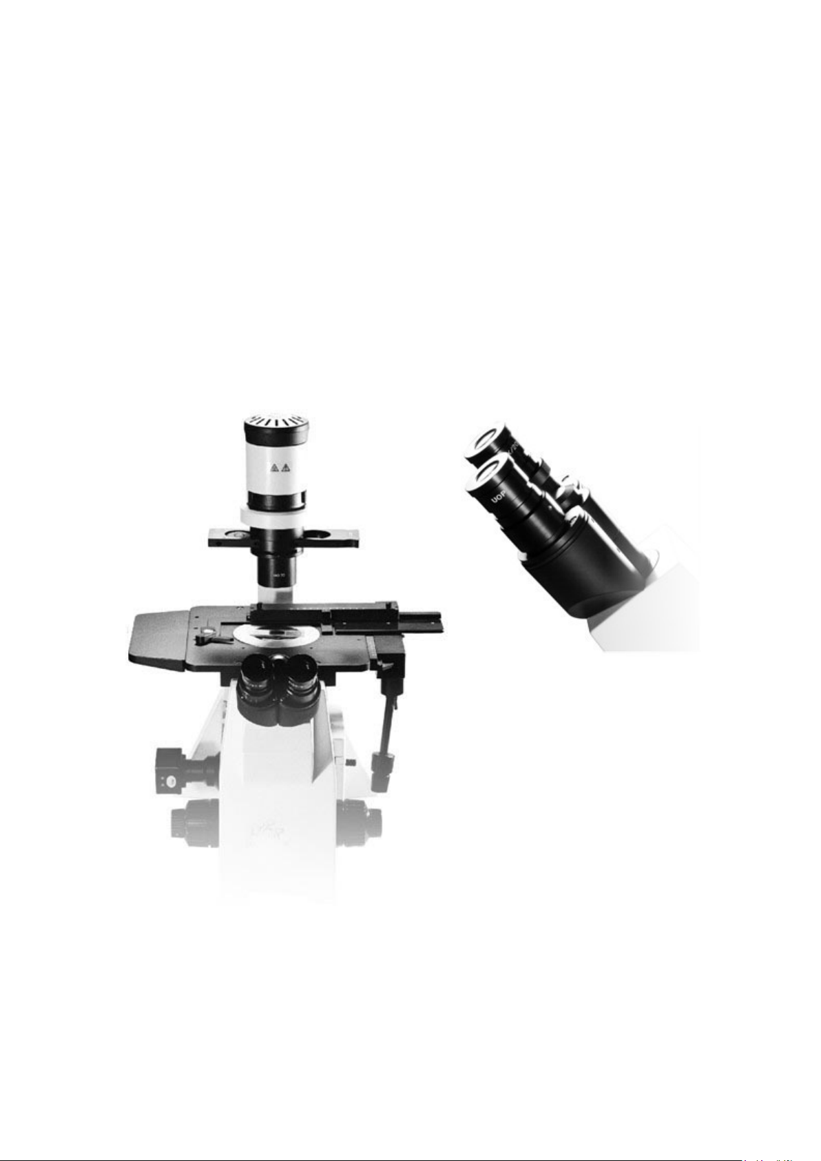
1. Introduction
Dear friend, thank you for using the inverted biological microscope made by our company. It is
our great honor to have you as our subscriber. In order to give you timely knowledge of how to
use the product, we have especially written this manual. Efforts have been made to ensure
thoroughness in contents, and brevity in style. It is our hope that you can get the basics about
the product such as its configurations, the ways to operate it, fault clearance, and maintenance.
A thorough and careful reading of the manual is strongly advised for your better use of the
product.
The biological microscopes use the UCIS infinity-corrected optical system which has been
developed by our company independently. This system, equipped with the infinity long-working
distance flat-field achromatic objectives, ultra long-working distance condenser and phase
contrast device also developed independently by our company, can be used for 22 ultra
long-distance and ultra wide-view observation. Inverted in structure, hence serving best the
observations of the living body in the culture dish, it is a high precision instrument essential to
cell cultivation
appraisal
The microscopes are used in many practical areas as well, such as bio-medical science,
preventive medication, environmental engineering, food processing, pharmaceutical chemical
engineering, agriculture, forestry, education, research, etc.
This inverted microscope has a huge upgrading potential. To meet the demand of pilot science
and technology, the microscope is composed of modularized accessories, making upgrading and
reconfiguration easily possible. It can take on various parts for different purposes, such as the
fluorescence observation system, the phase contrast observation system, the polarization
observation system, etc. and it has interfaces for special devises required by modern high-tech
fields, such as diaphragm clamp, thermostat shield, thermostat specimen stage. To ensure
yourself timely post-sales service (online consultation, telephone consultation, house calls for
repairs), please make timely registration of your working unit and the product. (Please refer to
the post-service receipt for detailed information.)
,tissue cultivation, and gene studies. It is also extensively used in water quality
,food inspection,and chemical reactive precipitation and crystal structure analysis.
2. Safety Symbols
The microscope has the following symbols. Make sure you have good understanding of their
meanings. Please use the microscope in safe ways as suggested.
Symbol meaning Explanation
Indicates that the surface becomes hot, and
should not be touched with bare hands.
Before use, carefully read the instruction
manual, improper use could result in personal
injury to the user and/or damage to the
equipment.
1
3. Meaning of the text symbols.
Caution: Negligence of the warnings in the manual may cause Physical harm or
mechanic damage (the objects nearby may also be affected).
!
Caution: Negligence of the warnings in the manual may cause Physical harm or
mechanic damage (the objects nearby may also be affected).
A reminding notice (for easy operation and maintenance)
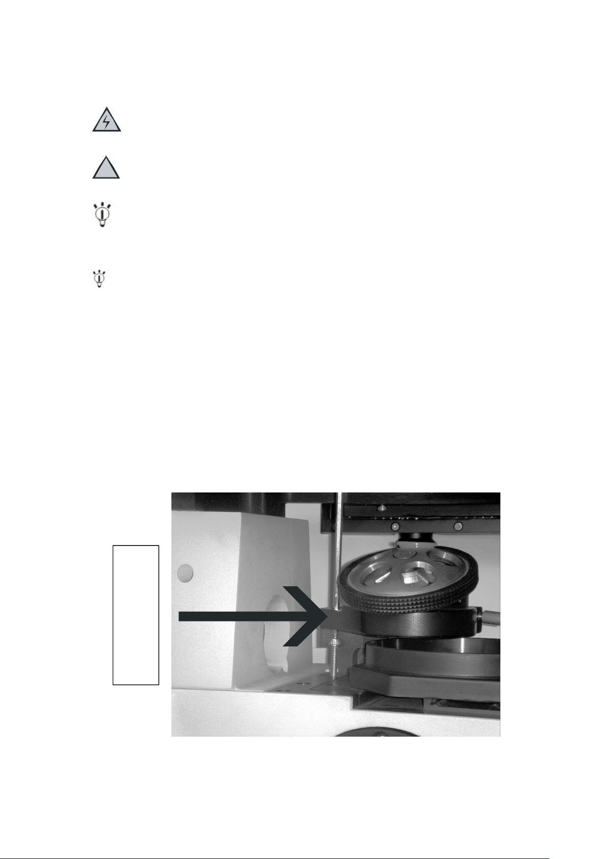
4. Precautions When Unpacking the Microscope
4-1 Releasing the Transport Lock of the Revolving Nosepiece
Never attempt to rotate the coarse or fine adjustment knob without removing the clamping
rod. Otherwise, the focusing mechanism may be damaged.
(1) Loosen he screw of the clamping rod using the Allen screwdriver provided with the
microscope frame.
(2) Rotate the coarse and fine adjustment knobs in the direction of the arrow and remove
the clamping rod.
Retain the clamping rod and screw carefully because they will be used again the next time
the microscope is transported.
4-2 Stage
Before transporting the stage, fix the flexible knobs with pieces of adhesive tape so that
they will not move.
Set pin of nosepiece
2
(Diagram
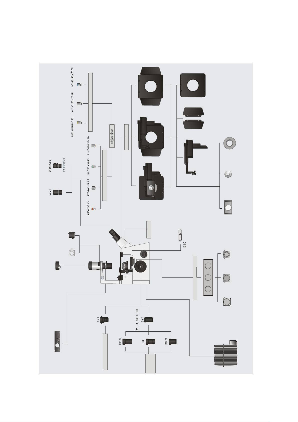
5. Module Nomenclature See diagram 1
PH UCIS object ive
sp eci men sta ge
UCIS obj ective
auxiliary stage addres s pla in holde r
re cta ng ular st age
Wit h flexible right handle
teardrop s ta ge
inser tpl ate 60mm Petridish ho lder v
cent erin g telescop e
76x26 haemacyto
Meter pl ate holder
DIC polarize r
Lambda Pla te
bulb co ver
C-mount video po rt
Phas e sl ide
camera
Obj ect ive
DSZ main body
C-mountdigitalport
Anal yzer
three-position sliderreflector
C-mountdigital
C-mountvideo
Camera
Lanp chamb er
3

6. Preparation for use
6-1
6-3
Please refer to diagram 1 on page 3 about the names
of the following items.
6-1 Attaching the Eyepieces
6-1-1 Remove the eyepieces' dust caps.
6-1-2 Insert G10X eyepiece into the eyepiece sleeve.
6-2 Attaching the Objectives
6-2-1 Remove the stage center plate and attach the
objectives to the revolving nosepiece through the hole
on the stage left by the plate.
6-2-2 Attaching the objectives in such a manner that
the magnification increase from low to higher powers
in the clockwise direction.
6-2-3 In the inverted microscope, the front lens of the
objectives faces upward, and is more exposed to
contamination than the objectives of upright
microscopes. Therefore, if there are empty positions
6-2
6-3 Attaching the fixator of the universal handwheel
6-3-1 This is an optional part which can be attached
according to your demand.
6-3-2 Joint the fixator to the stage with hexagonal
screws on , and to the connecting-rod of the
6-4 Attaching the Stage
6-4-1 Gently place the stage on the microscope frame by
aligning the stage mounting holes with the threaded
holes on the frame.
6-4-2 Insert the provided Allen screws into the mounting
holes. Tighten the screws using the
provided Allen wrench.
6-4-3 The stage is designed very thin so that the objective
will not hit it when the revolving nosepiece is rotated. Do
not subject the stage centeplage to impact or excessive force, as this may deform it.
6-4
4

6-5 Attaching the Holder for 76mm * 76mm slice
6-5-1 This part is used for the observation of the76mm *
76mm slice.
6-5-2 Open the spring clip of the rectangular stage with
flexible right handle, slide the holder into its right
position (Be sure that the rectangular groove facing up),
loose the clip gently, and finally put the Slice in place.
6-6 Connecting the Cables
6-6-1Cables and cords are vulnerable when bent or
twisted. Never subject them to excessive force.
6-6-2 Make sure that the main switch of the power
supply is set to "O"(OFF) before connecting cables.
(1) Connect the plug of the lamp housing or
illumination column to connector firmly.
(2) Connect the manual controller.
6-5
6-6-1
6-6-3 Be sure to supply power from a grounded, 3-conductor
power outlet using the proper cord is provided. If the
power outlet is not grounded properly, we can no longer
warrant the electrical safety performance of the
equipment.
6-6-4 If the power cord or a connection cable comes in
contact with the lamp housing or surrounding
equipment, the cord or cable may melt and result in
shock hazard. To prevent this, distribute the cords and
cables apart from the lamp housing.
6-7 Attaching the Phase Contrast Optical Slider
6-7-1 This is an optional part for the observation of
phase contrast.
6-7-2 The phase contrast slide can be removed when no
relevant observation is conducted.
6-7-3 Attach the phase contrast slider to the illumination
column so that the slider's indication surface faces
upwards and the finger hook position comes on the right.
6-7-4 The phase contrast slide should be matched with the
objectives during the observation.
6-8 Attaching the Filters
6-8-1 Select the proper filter according to your need.
6-6-2
6-7
5

6-8-2 While holding the mounting lever of the
filter holder, insert a filter.
(1) Hold the filter by its edge to avoid leaving
fingerprints or smudges on the filter surfaces.
(2) After the illumination has been ignited, the
filter will be very hot. Be sure to set the main
switch to "O"(OFF) and allow the filter holder and
filters to cool down before replacing filters.
6-8-3 Engage each filter in the light path by moving
the filter holder in the direction of the arrow.
6-9 Attaching the Photomicrographic System
6-9-1 This is an optional part for the
photomicrograph.
6-9-2 Using the Allen screwdriver, loosen the
clamping screw and remove the cap.
6-9-3 Align the index of the straight photo tube with
the positioning index on the side port and fit the
straight photo tube.
6-9-4 Tighten the clamping screw firmly.
6-9-5 When the side port is not used, attach the cap for
protecting it from dust.
6-9
6-10 Attaching the TV Observation System
6-10-1 This is an optional part for TV observation.
6-10-2 Attaching the photographic eyepiece and
adaptor on the side port.
6-10-3 Connect the CCD camera with screw thread
to get images that art brighter and higher in
resolution.
6-10-4 For the TV adaptor systems, refer to the instruction
manual for the TV adaptor to be used.
7. Preparations for the use of special devices
7-1 Attaching the fluorescence device of inverted
microscope. (Please refer to the specifications for
installation of Fluorescence device.)
7-2 Attaching the polarization device of inverted
microscope. (Please refer to the specifications for
installation of polarization device.)
7-3 Attaching the patch clamp, thermostatic
cover and the thermostatic stage.
7-3-1 Remove the cover of the 4 positions, and link
the patch clamp, thermostatic cover, and the thermostatic
stage to the microscope with the special screws provided by our company.
6-10
7-3
6
7-3-2 For detailed information, please refer to the specifications about patch clamp,
path selector lever.
Adjust the brightness.
path and bring the specimen in focus.
path.
insert the WY1 central telescope.
Adjust phase contrast.
and insert the 10X eyepiece.
thermostatic cover, and the thermostatic stage.
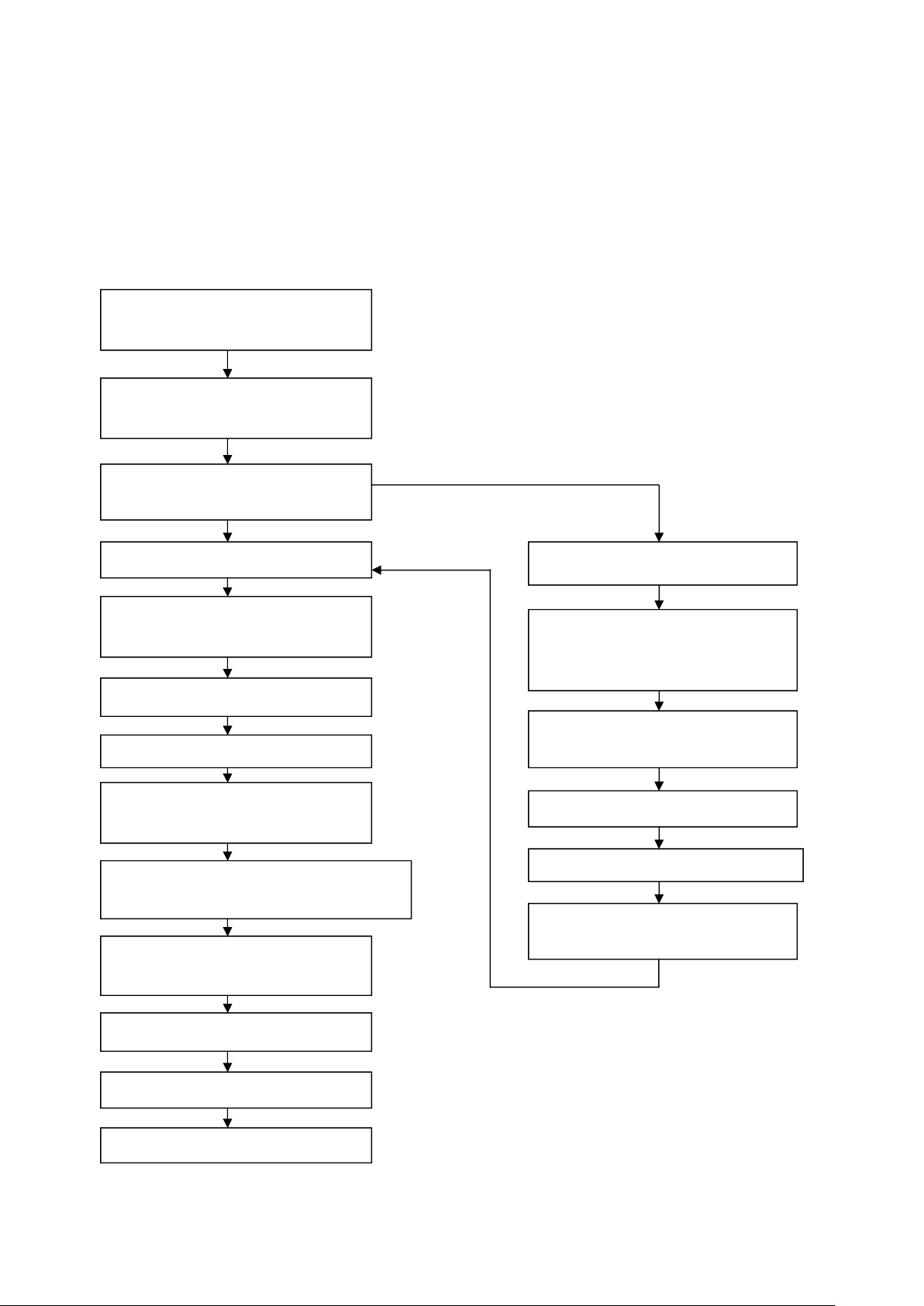
8. Operations
8-1 The procedure of transmitted light bright field observation and phase contrast observation,
please refer to diagram 2 in page 08. For more detail information, please refer to 8-2 and 8-3.
Transmitted light brightfield observation
Set the main switch to "I"(ON) and
adjust the intensity of illumination.
Disengage the filter other than the
frost filter from the light path.
Phase contrast observation
Select the light path with the light
Place the specimen on the stage.
Engage a 10X objective in the light
path.
Bring the specimen into focus.
Adjust the interpupillary distance
and the diopter
Engage the objective to be used in the light
Adjust the aperture iris and field iris
diaphragms.
Attaching the phase contrast slider.
Engage the objective matched with
the phase contrast slider in the light
Disengage the 10X eyepiece and
Adjust the aperture iris.
Disengage the WY1 central telescope
Engage the required filters.
Adjust the brightness.
Start observation.
7

8-2 The details of transmitted light brightfield
8-2-3
observation procedure
8-2-1 Set the main switch to "I"(ON) and adjust the
intensity of illumination.
A. Make sure that the light intensity control knob is in
the MIN(minimum intensity)position and set the main
switch to "I"(ON).
B. Rotate the knob toward MAX(maximum intensity)to
increase the intensity and the illumination brightness.
C. When the microscope system is not be used for a long
period,set the main switch to "O"(OFF).
8-2-2 Disengage the filter other than the frost filter
From the light path. (Please refer to 6-8.)
8-2-3 Select the light path with the light path
selector lever. The light path selector lever allows for
light path switching between the observation and side
port paths.
8-2-1
8-2-4 Place the specimen on the stage.
8-2-5 Engage a 10Xobjective in the light path.
8-2-6 Bring the specimen into focus.
(1) Rotation Direction of the Coarse/Fine Adjustment Knobs
Rotating the coarse or fine adjustment knob toward
the front(in the direction of the arrow) raises the objective
and toward the rear(opposite direction)lowers the objective.
(2) Adjusting the Coarse Adjustment Knob Tension
Always use the rotation tension adjustment ring to
control the rotation tension of the coarse adjustment knob.
The tension of coarse adjustment knob has been
pre-adjusted to optimum tension, but this can be changed as required. Turn the rotation tension
adjustment ring in the direction of the arrow to increase the knob's tension and in the opposite
direction to decrease it.
If the objective lowers by its own weight or the focusing obtained with the fine
adjustment knob is lost soon, the tension is set too low. In this case, turn the rotation tension
adjustment ring in the opposite direction to the arrow to increase the tension.
8

(3) Detaching the Fine Adjustment Knob
8-2-8
The fine adjustment knob is designed detachable in order to
prevent interference between the knob and the operator's
hand manipulating the X- and Y- axis knobs.
Loosen the clamping screw using the Allen screwdriver and
remove the fine adjustment knob.
After detaching, the seat of the fine adjustment knob is
hollowed to facilitate manipulation with the thick of a finger.
(4) Pre-focusing Lever
The pre-focusing lever prevents collision between the
specimen and objective and simplifies the focusing operation.
After bring the specimen into approximate focus with the coarse adjustment knob, turn the
pre-focusing lever in the direction of the arrow to lock it. Hereafter, the upper limit of the coarse
adjustment will be limited at the position where the lever is locked.
When bringing a specimen in focus, approximate focus can be obtained by simply raising the
coarse adjustment to the stop position so all you have to do more is control the fine adjustment
knob. The stage up/down movement using the fine adjustment knob is not limited.
When the pre-focusing lever is locked, the coarse adjustment stroke is limited by the
mechanism and it cannot reach the previous lower limit. If you want to control the coarse
adjustment knob to the previous lower limit, unlock the pre-focusing lever.
8-2-7 Adjust the brightness. (Please refer to 8-2-1)
8-2-8 Adjust the interpupillary distance.
While looking through the eyepieces, adjust the binocular
vision until the left and right fields of view coincide completely.
The index dot indicates the interpupillary
Distance.
Note your interpupillary distance so that it can be quickly
duplicated.
8-2-9 Adjust the Diopter
The diopter adjustment accuracy can be improved by using
an objective with as high power as possible.
(1)While looking through the left eyepiece, rotate the
diopter adjustment ring on the left eyepiece to bring the
specimen into focus.
(2)Looking through the right eyepiece, adjust the
coarse/fine adjustment knobs to bring the specimen to bring
the specimen into focus.
8-2-9
8-2-10 Engage the objective to be used in the light path and bring the specimen in focus.
8-2-11 Adjust the aperture iris.
9

8-2-12 Insert the filters(Please refer to 6.8)
8-2-13 Adjust the brightness
8-2-14 Start observation
8-3 Observation of phase contrast
8-3-1 Set the main switch to "I"(ON)(Please refer to 8.2.1)
8-3-2 Disengage the filter other than frost filter from the light path.
8-3-3 Select the light path with the light path selector lever.
8-3-4 Attach the phase contrast slider.
8-3-5 Engage the objective matched with the phase contrast slider in the light path.
8-3-6 Disengage the 10X eyepiece and insert the WY1 central telescope.
8-3-7 Adjust the aperture iris.
8-3-8 Adjust the phase contrast.
Using the optical element centering knobs, turn the two
centering screws of the phase contrast slider so that the
ring slit image overlaps with the phase plate of the
objective.
8-3-9 Disengage the WY1 central telescope and
insert the 10X eyepiece.
phase slide
8-3-8
10

8-3-10 Place the specimen on the stage.
8-3-11 Bring the specimen into focus.
8-3-12 Adjust the brightness.
8-3-13 Adjust the interpupillary distance and diopter.
8-3-14 Engage the objective to be used in the light path and bring the specimen in
focus.
8-3-15 Adjust the aperture iris and field iris diaphragms.
8-3-16 Engage the required filters.
8-3-17 Adjust the brightness.
8-3-18 Start observation.
11

9. Troubleshooting Guide
Under certain conditions, performance of the microscope may be adversely affected by factors
other than defects. If problems occur, please review the following list and take remedial action
as needed.
If you cannot solve the problem after checking the entire list, please contact your local
representative for assistance.
Problem Cause Remedy
1.Optical System
a) The bulb does not light.
b) The bulb lights but the
field
of view is dark.
c) Field of view is obscured
or
not evenly illuminated.
d) The image glares. Aperture iris diaphragm is
f ) Visibility of the image is
poor:
Image is not sharp.
Contrast is poor.
Details are poorly visible.
Power cord of the power supply
unit is unplugged.
Main switch of the power supply
unit is not ON.
The bulb is burnt out. Replace the bulb
The voltage is too low Increase light intensity.
Revolving nosepiece is not in a
click position.
Light path selector knob is set
for the side port light path.
Too many filters are used. Reduce the filters to the
The stage central plate is
engaged in the optical path.
Light path selector knob is set
to an intermediate position.
Revolving nosepiece is in an
intermediate position.
A filter is stooped in an
intermediate position.
The frost filter is not engaged. Engage the frosted glass.
stopped down too far.
The front lens of the objective is
dirty.
Inappropriate slide or cover
glass thickness.
The optical parts are covered
with dust.
Ring slit and phase plate are
not centered.
Plug in the power cord.
Switch the main power switch
to “I”(on).
Make sure that the revolvong
nosepiece clicks properly into
place.
Set the knob to the binocular
eyepiece light path position.
minimum required.
Move the stage and place the
specimen again.
Set the light path selector
button to a click position
according to the purpose.
Engage the revolving
nosepiece at a click stop.
Set the filter at the
appropriate position.
Adjust the aperture iris
diaphragm.
Clean the objective.
Change the slide for one with
suitable thickness.
Clean them all.
Center then correctly.
12

Problem Cause Remedy
f ) V isibility of the image is
poor:
Poor contrast during
observation.
Replace the plastic culture
vessel with a glass vessel.
Image is not sharp.
Contrast is poor.
Details are poorly visible.
g) The image is blurred.
Objective is engaged
incorrectly in the light path.
Make sure that revolving
nosepiece clicks into place
correctly.
Specimen is tilted with respect
to the stage.
Place the specimen correctly
on the stage and secure it with
the specimen holder.
h) Field of one eye does not
match that of the other.
The interpupillary distance is
incorrect.
Adjust the interpupillary
distance.
Incorrect diopter adjustment. Adjust the diopter.
i)The coarse/fine adjustment
knobs will not rotate easily or
at all.
The transport lock is not
released
The rotation tension adjusting
Remove the transport lock.
Loosen it moderately.
ring is too tight.
The pre-focusing lever is
Unlock it.
locked.
j) The revolving nosepiece
lowers by its own weight or
The tension adjustment ring is
too loose.
Tighten the ring optimally.
defocusing occurs due to
slipping of fine adjustment.
The coarse focus adjustment
cannot move the objective
The pre-focusing lever limits
the lower limit.
Unlock the pre-focusing lever.
above a certain level.
Notice:
1 Attaching the Halogen Bulb
(1) Do not touch the halogen bulb directly. If it is stained with fingerprints,etc.,wipe off
completely with a soft cloth in order to prevent shortening of the bulb life of cracking of the
bulb.
Hold the halogen bulb with gloves or a piece of gauze, insert the bulb pins straight and fully into
the pin holes on the lamp socket.
Push in gently. If an excessive force is applied or
the bulb is twisted, the bulb may be damaged.
(2) Caution for bulb replacement during or right
after use.
The bulb, lamp socket and areas near these will
be extremely hot during and right after use.
Set the main switch to "O"(OFF), disconnect the
13

power cord from the wall outlet, then allow the old bulb and lamp socket to cool before
replacing the bulb with a new of the designated type.
2 Attaching the Lamp Socket
Insert the plug into the socket, then push the guide pins gently into the guide holes.
10. Maintenance of the microscope
1. Clean all glass components by wiping gently with gauze. To remove fingerprints or oil
smudges, wipe with gauze slightly moistened with a mixture of ether(75%) and alcohol(25%)
To clean the extremity of an immersion objective, use neutral detergent. Do not use the
ether/alcohol mixture for cleaning , for these will deform the electrically insulated section of the
extremity.
Since solvents such as ether and alcohol are highly flammable, they must be handled
carefully.Be sure to keep these chemical away from open flames or potential sources of
electrical sparks - for example, electrical equipment that is being switched on or off. Also
remember to always use these chemical only in a well-ventilated room.
2. Be sure to clean the oil immersion objective after use. Leaving immersion oil on it will
degrades its performance.
3. Do not attempt to disassemble any part of the microscope.
4. When not using the microscope, make sure to set the main switch to "O"(OFF), confirm that
the lamp housing is cool enough and cover the microscope with the provided dust cover.
14
 Loading...