

Page 1

Page 2

40
Table of contents page
1. Introduction .................................................................................................. 42
2. Technical Data, Standard accessories, Denominations .......................... 43
2.1 Technical Data ............................................................................................... 43
2.2 Scope of delivery ........................................................................................... 43
2.3 Denominations ............................................................................................... 44
3. Putting into operation ................................................................................. 45
3.1 Power supply ................................................................................................. 45
3.1.1 Mains power supply ....................................................................................... 45
3.1.2 Battery power supply ..................................................................................... 45
3.2 Loading the paper roll .................................................................................... 46
4. First steps ..................................................................................................... 48
5. Operation mode ........................................................................................... 50
5.1 Switching On/Off (ON/OFF) ........................................................................... 50
5.1.1 Switching on (long pressing). ......................................................................... 50
5.1.2 Switching off (short pressing): ....................................................................... 50
5.1.3 Displaying the supply voltage ........................................................................ 50
5.2 Paper feed (FEED) ........................................................................................ 50
5.3 Tolerance display/changing tolerance value (TOL) ....................................... 51
5.3.1 Displaying tolerance ...................................................................................... 51
5.3.2 Inputting the tolerance ................................................................................... 51
5.4 Transferring measuring values ...................................................................... 52
5.5 Delete a measured value ............................................................................... 52
5.5.1 Delete an individual measured value ............................................................. 52
5.5.2 Delete an old measured value ....................................................................... 52
5.5.3 Deleting a measuring value (all measured values) ........................................ 53
5.6 Calculate statistics ......................................................................................... 53
5.7 Leafing through a measuring list .................................................................... 53
5.8 Printing a measuring list ................................................................................ 53
5.9 Documenting the adjustment (GLP) .............................................................. 54
6. Setting mode ................................................................................................ 55
6.1 Menu guide .................................................................................................... 55
6.2 Overview: Setting mode ................................................................................. 56
6.3 Protocol .......................................................................................................... 57
6.3.1 Statistics ........................................................................................................ 57
6.3.2 Statistics with histo-gram (Stat./Histogr.) ....................................................... 58
6.3.3 Sample chart .................................................................................................. 58
6.4 Print values .................................................................................................... 59
6.5 Full indication ................................................................................................. 59
6.6 Protocol header ............................................................................................. 60
6.7 Subgroup size (sam. size) ............................................................................. 60
6.8 Auto Data (Time-controlled automatic data transfer ) .................................... 60
6.9 ASCII – Printer ............................................................................................... 61
6.10 Acoustic signal ............................................................................................... 62
6.11 Interface ......................................................................................................... 62
6.12 Date, Time ..................................................................................................... 62
6.13 Measuring unit ............................................................................................... 63
6.14 Language ....................................................................................................... 63
6.15 LCD-contrast .................................................................................................. 63
Page 3

41
7. Edit parameter ............................................................................................. 64
7.1 Editor function ................................................................................................ 64
7.2 Edit time interval ............................................................................................ 65
7.3 Edit weight unit .............................................................................................. 66
7.4 Edit Date, Time .............................................................................................. 67
8. Additional functions .................................................................................... 68
8.1 Initialisation of the internal memory ............................................................... 68
8.2 Printer Self-test .............................................................................................. 68
Appendix
A Error messages and references .................................................................... 69
B Available optional accessories ...................................................................... 72
C Overview scales and data cables .................................................................. 72
D Scale configuration ........................................................................................ 73
E Collection of formulas .................................................................................... 74
F Operation flow chart ...................................................................................... 76
Page 4

42
1. Introduction
Prior to first use of the Statistic Printer YKT-01, we recommend that you read these operating
instructions very carefully.
The statistics printer YKT-01 is fitted with a thermal printing unit.
It has an interface for connecting electronic scales.
Range of application
Incoming and outgoing inspection, production, quality assurance
Specifications
• Up to 999 measured values can be stored (Logger-function)
• Two-line, alphanumerical display à 16 characters to display settings or error and status
messages in dialogue mode
• Operation with mains supply or with optional 6 Standard accumulator batteries AA 1,2 V
(accumulator batteries cannot be loaded via the delivered mains supply)
• High speed print, print-out on thermopaper
• No loss of data in case of voltage loss
• Possibility as Interface to RS 232C
• multilingual (German/French/English)
Safety and general notes
• Make sure that the electrical connection data prescribed for the plug-in charger are
observed.
• Connect and disconnect data in-and output only when the printer is switched off
or disconnected.
• Protect the instrument against humidity, dust and aggressive media.
Keep the printer mechanism clean from dust by wiping it with a dry cloth from time to time.
• No connection of data cables with a length of more than 3 m.
• In the event of optional use of accumulators, dispose of used accumulators in accordance
with regulations.
• Storage temperature: -10 °C to +50 °C
• Operating temperature: +5 °C to +40 °C
The Statistic Printer YKT -01 is in comformity with EU-Standards 89/336/EWG
concerning electromagnetic compatibility and the directive on low voltage 73/23/EWG.
Should you have any questions regarding the instrument, please do not hesitate to contact us.
Page 5

43
2. Technical Data, Standard accessories, Denominations
2.1 Technical Data
Measured values max. 999
Characters per line 24
Paper width 58 mm
LxWxH 215 x 116 x 85 mm
Battery powered by 1100 mAh > 7000 printed lines
Datalogger by accu. operation ca. 24 hours
Protection class IP 40
Total weight incl. accu * 600 g
2.2 Scope of delivery
YKT -01 Statistic printer in plastic case
complete with:
Mains supply adapter
Paper rolls
Operating Instructions
UK-Adapter
Page 6

44
2.3 Denominations
9
12
2
4
7
6
1
5
3
1 Housing
2 Control panel
3 Printer cover
4 ON/OFF-switch
5 Printout
6 Alphanumerical display
7 Tolerance-LED
8 not proved by documents
9 Data-input from measuring instrument
RS 232 (INPUT)
10 not proved by documents
11 not proved by documents
12 Connector to mains power supply
13 Battery compartment cover
Page 7

45
3. Putting into operation
3.1 Power supply
Connect the statistics printer with the supplied mains power adapter to a mains power source
or insert 6 standard batteries AA 1,2 V.
3.1.1 Mains power supply
- Connect the mains power adapter to the mains (observe the voltage) and with the 12 pin
connector socket.
- Only use the supplied mains power adapter.
3.1.2 Battery power supply
- Remove cover 14 observing the arrow direction on the rear side of the instrument.
At the same time this cover closes the battery compartment:
- Insert batteries, check the polarity on the underside of the instrument.
- Replace the cover.
13
Page 8

46
3.2 Loading the paper roll
- Switch off instrument.
- Move printer cover 3 backwards (a) and take it off.
- Remove the plastic shaft and guide the new paper roll core onto it (when changing
paper: Take out plastic shaft and remove the old roll core and if necessary any paper
parts that have remained in the printer).
Manual Feed
- Open clamp (b) in the printer.
- Place the new paper roll on the table behind the printer and unwind ca. 15 cm.
Note: Unwind the paper from the underside (see picture below), the paper end must
be a straight, clean-cut.
- Switch the unit on. On the display appears in the Start menu the following command
„Load paper!“
Page 9

47
Automatic Paper feed
- Clamp (d) of the printer is closed.
- Place the new paper roll on the table behind the printer and unwind ca. 15 cm.
- Switch the unit on. On the display appears in the Start menu the following command
„Load paper!“.
- Guide paper through the underside of the paper feed (c) until the paper is
automaticlly pulled through.
- Open clamp (b) of the printer and arrange the paper.
- Close clamp (d).
- Insert the paper roll on the roller locator in the printer.
- Slide the end of the paper roll through the slot in the printer cover (e) and replace the
printer cover onto the housing (f).
- The Statistics Printer YKT-01 is now ready to print.
- Guide paper through the underside of the paper feed (c) until the paper appears.
- Arrange paper, ensuring it is straight.
- Close the clamp (d).
- Insert the paper roll on the roller locator in the printer.
- Pressing the FEED key enables a paper feed, this depends on how long this key is
pressed. The paper end should protrude 3-5 cm over the printer head.
- Slide the end of the paper roll through the slot in the printer cover (e) and replace the
printer cover onto the housing (f).
- The Statistics Printer YKT-01 is now ready to print.
Page 10

48
Press to set the data and time.
In the display the cursor flashes on the weekday field e.g. Mo
With or the current day can be selected.
With the cursor moves to the next input position (Day, Month, Year,
Hour, Minute, Second)
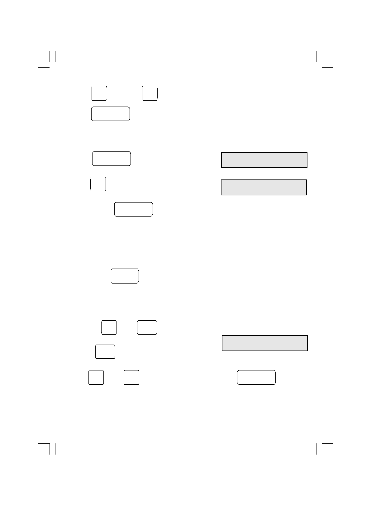
4. First steps
=> Establish a power supply, see Chapter 3.1
=> Loading a paper roll, see Chapter 3.2
=> Basic set-up
Setting up of Language, Measuring unit and Date/Time
Press following appears in the display: e.g
Press and in the display appears
Press again, in the display appears
With or the required language can be selected.
Subsequently press in the display appears
With or select the desired weighing unit (mg/g).
Subsequently press in the display appears
Protocol
Statistics
L C D - c o n t r a s t
9
L a n g u a g e
E n g l i s h
M e a s . u n i t
m g
D a t e , T i m e
( S t a t )
M o 0 0 . 0 0 . 0 0
0 0 : 0 0 : 0 0
▼
▼
▼
▼
▼
▼▼
▼▼
▼
ENTER
▼
▼
▼▼
▼
▲▲
▲▲
▲
▼▼
▼▼
▼
▲▲
▲▲
▲
▼▼
▼▼
▼
▼
▼
▼
▼
▼
▲▲
▲▲
▲
STAT
▲▲
▲▲
▲
▼▼
▼▼
▼
Page 11
49
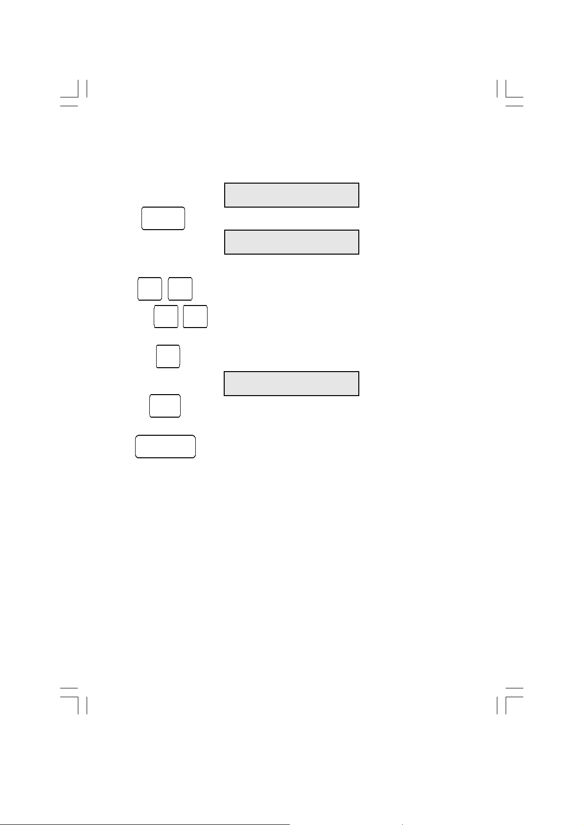
=> Select Interface:
Press in the display appears
the selected scale model
Press several times until in the display appears
The selected scale model appears.
Conclude with to confirm selection
I n t e r f a c e
xxx
With or the current date and time can be set.
With the settings are confirmed and the basic settings are concluded.
=> Delete measured value:
With or key a single or all values will be deleted.
Press in the display appears
With or select yes or no and confirm with .
Of course the YKT-01 Statistics Printer offers a wide range of possibilities and ranges
to optimize and support your measuring and quality requirements. A detailed
explanation and reference guide can be found on the following pages.
=> Receive and print a measured value:
With the key on the YKT-01 or the function key on the scale the
measuring values are transferred to the printer.
D e l e t e a l l m e a s.
v a l u e s ? n o
I n t e r f a c e
440/572/C/D/KB
ENTER
▲▲
▲▲
▲
▼▼
▼▼
▼
ENTER
▼▼
▼▼
▼
ENTER
ENTER
▲▲
▲▲
▲
▼▼
▼▼
▼
C AC
DATA
AC
Page 12

50
Long pressing: > 1 sec., short pressing: < 1 sec.
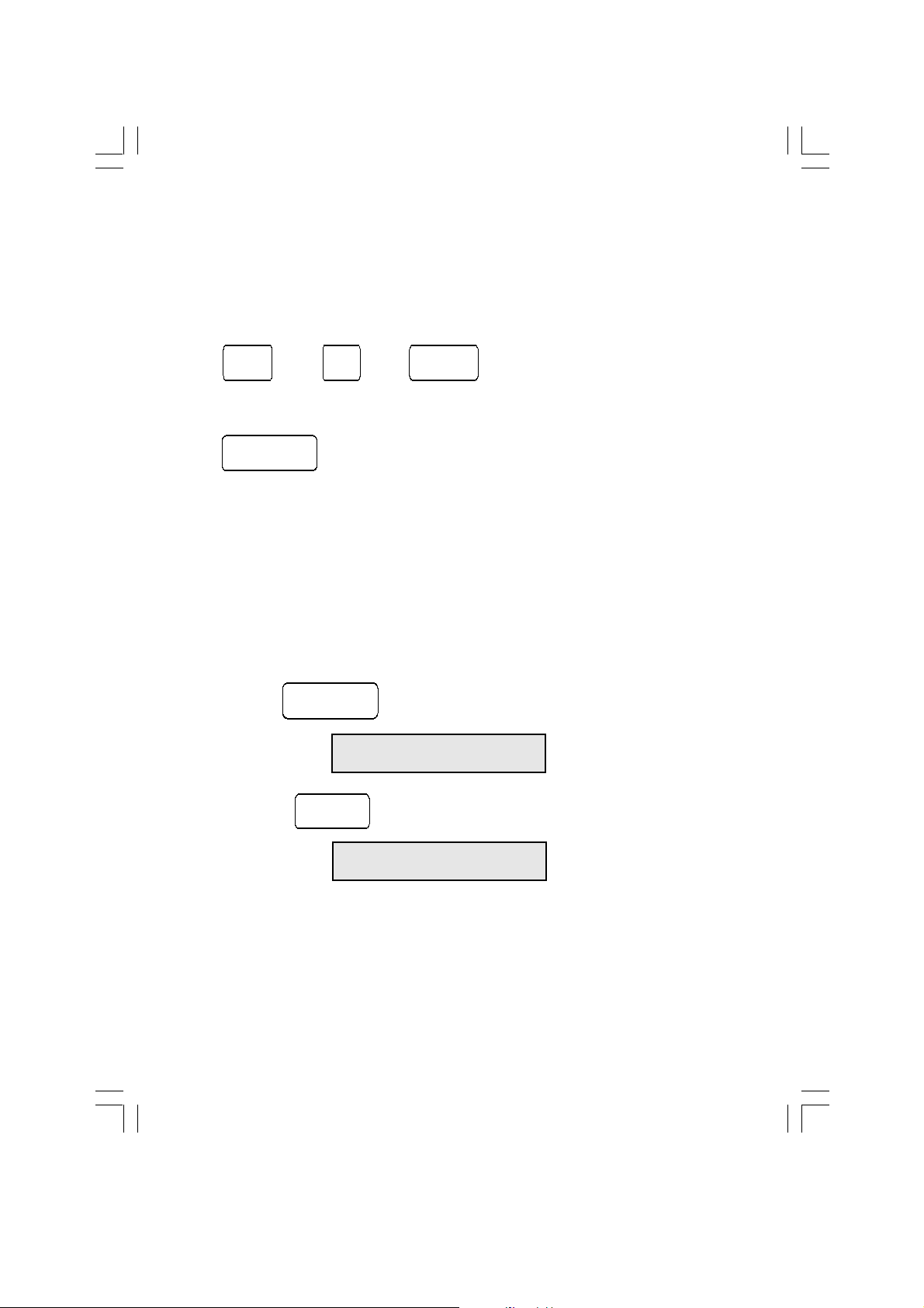
5.1 Switching On/Off (ON/OFF)
Switching ON and OFF, supply voltage display
5.1.1 Switching on (long pressing).
The following appears in the display after switching on:
If there is no previous measuring series, then after 2 seconds appears in display:
If there is an existing measurement series, then after switching on the measuring value with
the highest measuring value number will appear.
After receiving a measuring value this remains in the display.
5.1.2 Switching off (short pressing):
5. Operation mode
TOL AC C
ENTER
FEED DATA
STAT
ON
OFF
Keyboard
O F F
N o . 1 7 1 2 . 3 4 5
m g
F r 1 2 . 1 1 . 0 1
1 0 : 1 3 : 4 0
YKT-01 V 1 . 4
W e l c o m e
5.1.3 Displaying the supply voltage (long pressing, hold until in the display appears):
5.2 Paper feed (FEED)
short pressing: feeds 1 row
long pressing: continuous feed until the key is released
S u p p l y v o l t a g e 7.5 V
FEED
OFF
ON
Page 13

51
5.3 Tolerance display/changing tolerance value (TOL)
5.3.1 Displaying tolerance
short pressing: Current tolerances will appear in the display.
The cursor will appear on the sign of the Upper Tolerance.
Attention:
The input or changing of a tolerance value is only possible when the measuring series is
deleted with the AC key. Within a series of measurements, tolerance values are only shown
on the display, manifested by the absence of a flashing cursor.
O . T o l ± 1 0 0 . 0 0 0 0
U . T o l + 9 9 . 5 0 0 0
5.3.2 Inputting the tolerance
With keys can the selected position be edited
With keys the selected position be can edited. Valid entries are the
numbers 0 to 9 and the signs “ + “, “ - “ and “ . “
Note:
- The default value is zero.
- The maximim number of positions including sign and decimal point is 10.
- This may only include 6 digits after the decimal point.
- It is permissable to enter any character of your choice in the 10 available positions.
- Positions remaining vacant between the numerals will be filled in during saving by
moving them to the right.
- After saving, the numerals will be right aligned
With key the character where the flashing cursor is positoned can be deleted.
With can the whole figure be deleted and the cursor will return to the input field.
With key it is possible to alternate between the upper and lower tolerance
values.
With is the input of tolerance value concluded, the tolerance value is saved
and the input menu can be exited.
TOL
▼
▼
▼▼
▼
▲▲
▲▲
▲
▲▲
▲▲
▲
▼▼
▼▼
▼
AC
C
ENTER
TOL
Page 14

52
N o . 1 7 1 2 . 3 4 5
d e l e t e d m g
N o . 1 0 1 2 . 3 4 5
d e l e t e d m g
N o . 1 7 1 2 . 3 4 5
m g
DATA
C
▼▼
▼▼
▼
▲▲
▲▲
▲
C
C
5.4 Transferring measuring values
Measuring values are accepted either using the function(print) key (data transfer) at the
scales or using the DATA key on the YKT -01. They will then be shown on the display and also
printed if „print measuring value“ has been activated.
5.5 Delete a measured value
5.5.1 Delete an individual measured value
Whether one or several values have been received, with the present value shown in the
display can be deleted.
An acoustic signal is issued. If this is the last measuring value, it will be marked by a strike
through on the printout. When there are 6 spaces between the last measured value and the
actual position of the paper, the value can no longer be struck through and will be treated as
an old measured value.
5.5.2 Delete an old measured value
If required to delete an old measured value, use or to display the value
and to delete with .
As the returnpaper feed is only able to execute one recording step back, only the last printed
value will be struck through. Subsequently the actual printing item will be displayed with e.g.
“no. 10 cancelled!”.
If, starting with the highest reference number of the measuring values, always the penultimate
reference number is cleared, this number will become vacant and allocated to the next
accepted measuring value
If the cancelled value is not the one with the highest measuring value reference number then
this number will remain in use. When the value is shown on the display it will have the remark
„deleted“
The deleted values are not considered in the number of measuring values or in the statistical
evaluation.
Deleted values can be restored by pressing (press longer than 1 sec.).
Therefore the message e.g. „No.10 restored“ is printed.
Generally an acoustic signal is issued.
If no deleted value is selected, this function is not possible.
Page 15

53
5.5.3 Deleting a measuring value (all measured values)
Press, in the display appears
By pressing it is possible to abandon this menu without
deleting any of the measuring values
Select or with
and confirm with .
5.6 Calculate statistics
Via the key the statistics for the present values be calculated.
The reports:
- Statistics
- Statistics with histogram
- Sample chart can be selected.
For selection refer to Setting modes, chapter 6
5.7 Leafing through a measuring list
With the cursor keys it is possible to leaf back and forth within the list.
5.8 Printing a measuring list
The current measuring list can be printed as often as required.
Via the key the setting up mode is activated. With leaf through until
appears.
The current measuring sequence will be printed with
During a print-out the task, with can be switched off and with
the task is discontinued.
Return with to the Operating mode.
D e l e t e a l l m e a s.
v a l u e s ? n o
D e l e t e a l l m e a s.
v a l u e s ? y e s
P r i n t m e a s . l i s t
( D a t a )
AC
ENTER
▼▼
▼▼
▼
▲▲
▲▲
▲
ENTER
STAT
▲▲
▲▲
▲
▼▼
▼▼
▼
ENTER
▲▲
▲▲
▲
DATA
ON/OFF
FEED
ENTER
Page 16

54
5.9 Documenting the adjustment (GLP)
The YKT-01 is able to produce a GLP adjustment report.
Keep the key pressed for approx. 3 seconds.
The following report will be printed and can be completed by hand.
STAT
Documentation of
Adjustment (GLP)
Date: Time:
________ ________
Balance
Manufacturer: ________
Model: ________
Serial no.: ________
ID: ________
Adjustment weight
external internal
Serial no.: _______
Rated value: _______
Class: _______
____________________
Adjustment successful:
yes no
____________________
Auditor: ________
Signature: ________
Page 17

55
6. Setting mode
6.1 Menu guide
With you get from the working mode into the setup mode.
The currently selected interface will always be displayed. e.g.:
Main menu
Parameter
With the main menu is selected
With can the related parameters of the main menu be selected.
With can the setting mode at any point be abandoned.
Attention:
The current settings are confirmed with resp. accepted once there has been
a change to the next menu item.
At any point the setting mode is switched off and the new settings are saved.
I n t e r f a c e
440/572/C/D/KB
ENTER
▲▲
▲▲
▲
▼▼
▼▼
▼
▼
▼
▼▼
▼
▲▲
▲
▲
▲
ENTER
ENTER
Page 18

6.2 Overview: Setting mode
STAT
ss
ss
s
tt
t
t
t
ss
ss
s
tt
tt
t
Main menu Parameter menu Chapter Edit parameter Chapter
Report Statistics
Stat. / Histogr. 6.3
Sample chart
Print value yes 6.4
no
Send value not documented
Report header yes 6.6
no
Sample size 1 . . . 25 6.7
Auto. Data no 6.8 Edit time interval 7.2
yes
Print series 5.8
Send series not documented
ASCII – Printer 6.9
Acoust. Signal On 6.10
Off
Interface 440/572/C/D/KB
770/GS/GJ
AR/PR
<47x/EG/EW> 6.11
<AB>
<ITx/FTx>
Full indication yes
no 6.5
Date, Time 6.12 Edit date and time 7.4
Edit weighing unit mg 6.13 Edit weighing unit 7.3
g
kg
t
lb
ct
Language German
English 6.14
French
LCD-Contrast 0 . . . 16 6.15
56
Page 19

6.3 Protocol
The desired protocol can be selected.
After having made the selection the following appears on the display:
With
it is possible to switch to
or to
6.3.1 Statistics
ss
ss
s
tt
tt
t
Protocol
S t a t i s t i c s
Protocol
S t a t . /H i s t o g r.
Protocol
S a m p l e c h a r t
* Results *
Mo 09.10.02 13:45:15
n X
Max XX.XXX
Min XX.XXX
R X.XXX
x XX.XXXXX
XX.XXXXX
s X.XXXXX
s X.XXXXX
— — — — — — — — — — — — —
[ g ]
1. 19.992
2. 19.893
3. 18.887
4. 19.946
5. 20.557
6. 20.458
7. 20.432
57
Page 20

58
6.3.2 Statistics with
histogram (Stat./Histogr.)
U T 20.500
LT 19.900
Subgr.size 5
— — — — — — — — — — — —
[ g ]
1. 19.992
2. 19.893
3. 18.887 u
4. 19.946
5. 20.557 t
1 — — — —
6. 20.458
7. 20.432
8. 19.950
9. 19.321 u
10. 20.429
2 — — — —
11. 19.956
* Results *
Mo 09.10.02 13:45:15
n X
Max XX.XXX
Min XX.XXX
R X.XXX
x XX.XXXXX
XX.XXXXX
s X.XXXXX
s X.XXXXX
> UT X
< LT X
Def. % X
C m X.XXX
C m k X.XXX
Cp X.XXX
Cpk X.XXX
Sam.size 5
* Histogram *
U T 20.500
LT 19.900
Classes 10
Class limits:
A XX.XXX to
B XX.XXX to
C XX.XXX to
D XX.XXX to
6.3.3 Sample chart
U T 20.500
LT 19.900
Sam.size 5
— — — — — — — — — — — —
[ g ]
LT U T
+XXX.XXXX |h : |
+XXX.XXXX | h : |
+XXX.XXXX | h: |
+XXX.XXXX | : h |
+XXX.XXXX | h : |
1 — — — —
+XXX.XXXX | : !
+XXX.XXXX | : |
+XXX.XXXX | : |
+XXX.XXXX | : |
+XXX.XXXX " : |
2 — — — —
+XXX.XXXX | : |
+XXX.XXXX | : |
+XXX.XXXX | : |
* Results *
Mo 09.10.02 13:45:15
E XX.XXX to
F XX.XXX to
G XX.XXX to
H XX.XXX to
I XX.XXX to
J XX.XXX to
XX.XXX
UT X
— — — — — — — — — —
A X
B X
C X
D X
E X
F X
G X
H X
I X
J X
— — — — — — — — — —
LT X
n X
Max XX.XXX
Min XX.XXX
R X.XXX
x XX.XXXXX
XX.XXXXX
! X.XXXXX
s X.XXXXX
> UT X
< LT X
Def. % X
C m X.XXX
C m k X.XXX
Cp X.XXX
Cpk X.XXX
Sam.size 5
* Histogram *
U T 20.500
LT 19.900
Classes 10
Class limits:
A XX.XXX to
B XX.XXX to
C XX.XXX to
D XX.XXX to
E XX.XXX to
F XX.XXX to
G XX.XXX to
H XX.XXX to
I XX.XXX to
J XX.XXX to
XX.XXX
UT X
— — — — — — — — — — — —
—
A X
B X
C X
D X
E X
F X
G X
H X
I X
J X
— — — — — — — — — — — —
—
LT X
Page 21

59
6.4 Print values
After having made the selection the following appears on the display:
With can be selected.
When measurement list are accepted an acoustic signal will be issued.
6.5 Full indication
After having made the selection the following appears on the display:
The entire display is recorded, however special characters (e.g. verification labelling, /...) are
left out; the entire weighing value is printed out. For Example:
Display 0.0017/2 Printout 0.00172
With can be selected.
Display values are only recorded up to the special characters. Any additional values stated
after the special characters will be left out. For Example:
Display 0.0017/2 Printout 0.0017
P r i n t values
n o
P r i n t values
y e s
ss
ss
s
tt
tt
t
Full indication
yes
Full indication
no
ss
ss
s
tt
tt
t
Page 22

60
N o . 1 1 2 . 3 4 5
1 0 S e c m g
6.6 Protocol header
Once selected the following will appear on the display:
With can be selected.
Protocol h e a d e r
( S t a t ) y e s
Protocol h e a d e r
n o
Subgroup s i z e
5
6.8 Auto Data (Time-controlled automatic data transfer )
In regular time intervals the measured values can automatically be transferred.
After having made the selection the following appears on the display:
With can
be selected.
With can the parameter time interval be edited, see chapter 7.2
With the following appears on the display:
With the function is activated.
A u t o . D a t a
n o
STAT
A u t o . D a t a
( S t a t ) y e s
ENTER
S t a r t ( D a t a )
1 0 S e c m g
DATA
▲▲
▲▲
▲
▼▼
▼▼
▼
▲▲
▲▲
▲
▼▼
▼▼
▼
▲▲
▲▲
▲
▼▼
▼▼
▼
6.7 Subgroup size (sam. size)
Once selected the following will appear on the display:
With the value can be changed from 1 to 25.
Page 23

61
6.9 ASCII – Printer
After having made the selection the following appears on the display:
With one is taken to the ASCII receiving mode:
The cursor flashes at the top left hand corner position of the display. The commands Xon /
Xoff are active. Xon is sent after Xoff has been sent. The memory size amounts to 50 Byte. A
maximum of 32 characters can be seen in the display. A received CRLF returns the cursor to
the top left hand corner positon.
With can the whole display be deleted.
All possible characters will be printed.
With returns one to the following display:
With the time-controlled automatic data transfer is terminated
and goes back to
With can
be selected and
with can be terminated the time-controlled automatic data transfer function.
Note:
During the time-controlled automatic data transfer the following keys are locked:
TOL., AC, C, STAT and the cursor keys.
The keys that remain operational are: ON/OFF, ENTER, FEED and DATA.
ENTER
A u t o . D a t a
( S t a t ) y e s
A u t o . D a t a
n o
ENTER
A S C I I - P r i n t e r
( S t a t ) ( D a t a )
_
A S C I I - P r i n t e r
( S t a t ) ( D a t a )
AC
ENTER
DATA
▲▲
▲▲
▲
▼▼
▼▼
▼
Page 24

62
D a t e , T i m e
( S t a t )
STAT
6.10 Acoustic signal
Here the acoustic signal can for all functions be switched on or off.
There are 3 acoustic signals available:
1 x short for measuring value transfer
1 x long for deleting measuring value/measuring list
3 x short for Error messages
After having made the selection the following appears on the display:
With can
be selected.
6.11 Interface
The desired interface can be selected. After having made the selection the following appears
on the display:
With can be switched.
The interfaces referred to as: - 440/572/C/D/KB,
- 770/GS/GJ
- AR/PR
are programmed with fixed parameters. For suitable hand measuring instruments and data cables
see Appendix B.
The Interfaces referred to as: - < 47x/EG/EW >
-
< ABS/ABJ>
- <
ITx/FTx
>
have been assigned the appropriate parameters. For suitable hand measuring instruments and
data cables see Appendix B.
6.12 Date, Time
The data and time can be set here.
After having made the selection the following appears on the display:
With Date and Time can be edited, see chapter 7.2
A c o u s t ic S i g n a l
on
A c o u s tic S i g n a l
off
I n t e r f a c e
440/572/C/DKB
▲▲
▲▲
▲
▼▼
▼▼
▼
▲▲
▲▲
▲
▼▼
▼▼
▼
Page 25

63
6.13 Measuring unit
The desired measuring unit can be selected.
After having made the selection the following appears on the display:
With
can be switched to: (kg,t,ct,lb)
or:
or:
Meas. unit „——„ means that the measuring value will be issued without measuring unit
With the Weight unit can be freely edited, see chapter 7.3
Attention: If the measuring unit is changed, both tolerance limits are automatically set to zero
without Error message.
6.14 Language
Ther desired language can be selected.
After having made the selection the following appears on the display:
With
can be switched to:
or :
6.15 LCD-contrast
The contrast of the display has 17 levels and can be altered to the personal requirements of
the user. After having made the selection the following appears on the display:
With the LCD-contrast can be altered from 0 to 16.
M e a s . u n i t
m g
M e a s . u n i t
g
M e a s . u n i t
( S t a t ) <xxxx>
M e a s . u n i t
_ _ _ _
L a n g u a g e
D e u t s c h
L a n g u a g e
E n g l i s h
L a n g u a g e
F rancais
L C D - c o n t r a s t
9
▲▲
▲▲
▲
▼▼
▼▼
▼
STAT
▲▲
▲▲
▲
▼▼
▼▼
▼
▲▲
▲▲
▲
▼▼
▼▼
▼
Page 26

64
7. Edit parameter
7.1 Editor function
The display shows in the right hand corner the current editor mode.
With it can be switched as follows:
[>] refers to upper case ( A to Z )
[<] refers to lower case ( a to z and ä, ö, ü, ß)
[1] refers to numbers ( 0 to 9 )
[*] refers to special characters ( 20
H
to 2FH ; 3AH to 40H ; E6H)
[#] refers to following control characters: → CR
→ LF
❚ → End of string
→ 0,5 sec. pause
The cursor flashes at the first possible position that can be edited.
With the cursor can be moved to the position to be edited and
with the appropriate position can be edited.
A longer pressing of the keys enables a quick preview of the characters
in the respective editor mode.
With the edited position can be deleted. (spaces are entered)
With the whole display can be deleted. (spaces are entered)
P a r t n o . : [ > ]
_
DATA
¬
¬
▲▲
▲▲
▲
▼▼
▼▼
▼
AC
C
▲▲
▲▲
▲
▼▼
▼▼
▼
▼▼
▼
▼
▼
▲▲
▲▲
▲
Page 27

65
7.2 Edit time interval
After having made the selection the following appears on the display:
The key allows the selected parameter to be edited.
Using the keys this parameter will be altered.
.
With the cursor is moved under the unit and
with modified
Possible entries: 0...59 sec
0...59 min
0...99 hr
With one returns to the Main menu
A u t o . D a t a
1 0 S e c
A u t o . D a t a
( S t a t ) y e s
A u t o . D a t a
( S t a t ) y e s
STAT
▲▲
▲▲
▲
▼▼
▼▼
▼
▲▲
▲▲
▲
▲▲
▲▲
▲
▼▼
▼▼
▼
ENTER
Page 28

66
7.3 Edit weight unit
After having made the selection the following appears on the display:
With the
Meas. unit can be freely edited.
With the cursor can be moved to the next position
and with the appropriate position can be edited.
With one accepts the setting and returns to the Main menu .
Attention: If the weight unit is changed, both tolerance limits are automatically set to zero
without Error message.
M e a s . u n i t
( S t a t ) < x x x x >
M e a s . u n i t ( > )
< x x x x >
STAT
▲▲
▲▲
▲
▼▼
▼▼
▼
▼
▼
▼
▼
▼
▲▲
▲▲
▲
ENTER
Page 29
67
7.4 Edit Date, Time
After having made the selection the following appears on the display:
With can Date and Time be edited.
With the cursor can be moved to the next position
and with the appropriate position can be edited.
With the edited position can be returned to the lowest valid value. e.g.:
With one can return to the Main menu without saving any of the changes.
With the Main menu will be left. The changed date and the
time will be saved.
D a t e , T i m e
( S t a t )
F r 1 2 . 1 1 . 0 1
1 0 : 1 3 : 4 0
F r 1 2 . 1 1 . 0 1
1 0 : 1 3 : 4 0
STAT
▲▲
▲▲
▲
▼▼
▼▼
▼
▼▼
▼
▼
▼
▲▲
▲▲
▲
ENTER
C
AC
Page 30
68
8.2 Printer Self-test
In operating mode keep pressed until
appears.
Following this press for a short period.
In the display appears :
The available characters, date, time and voltage are printed, the LED is active and an acoustic
signal is sounded.
Supply v o l t a g e
7 . 5 V
YKT-01 V 1 . 4
S e l f t e s t !
8. Additional functions
8.1 Initialisation of the internal memory
Caution!
While switched off press the keys
+ +
simultaneously and press
to switch on the unit.
The internal memory will be re-initialised with the default values.
The previous settings will be lost !
AC C DATA
ON/OFF
ON/OFF
FEED
Page 31

69
Error messages and references
The task is always shown on the LCD-display.
An error message will be visible for approx. 1 or 2 seconds. An acoustic signal (3 x) is issued. Then the previous display will reappear.
Some error messages which require a decision or signal system failure have to be confirmed.
Note: When the acoustic signal is switched off, no error tone will be sounded.
Message/Error
L o a d p a p e r !
Cause
There is no more paper in the printer.
P r i n t e r
( E n t e r ) o f f
Remedy
Load paper (see
chapte 3.2) or:
With switch off the printer
in order to continue operation without paper.
In the display appears:
With confirm and
continue.
Appendix A
ENTER
ENTER
Page 32

70
Remedy
Change batteries/accu’s or plug in the
adapter or exchange the adapter.
Change the tolerances such that the upper
tolerance limit is larger or equal to the lo
wer
tolerance limit.
Note:
While entering the tolerance values, is
activated, the device is
switched off. Tolerance
changes will not be saved.
Use decimal point or sign only once per
value.
Correct to max. 999 values.
Cause
The operating voltage has dropped below
the 6.0 Volt limit. The unit is switched off
(Protection against excessive discharge).
1. The upper tolerance limit is not
bigger as or equal to the lower
tolerance limit.
2. Decimal point or prefix
exist several times.
Number of measuring values exceeds 999.
Message/Error
Approx. 5 sec:
and 1 sec:
ON/OFF
T o l . - E r r o r !
M a x i m u m
m e a s . v a l u e
O F F
V o l t a g e
t o o l o w !
Page 33

71
Remedy
Check on the measuring instrument that the
format conforms to the default.
Change the weighing unit at the YKT.
Check the connection to the interface.
Collect a new series of measuring values
e.g. abort and delete the series of
measurements. Subsequently alter the
sample size.
Cause
The measuring value may include a
maximum of 6 places after the decimal
point. The maximum number of digits
including the prefix and the decimal point is
10 digits. If this number is being exceeded,
an error message will be displayed.
The measuring unit of the measuring value
is selected in the set-up mode. When a
measuring instrument however is also
sending the measuring unit and this
deviates from the selcted unit, an error
message will appear.
When a measuring value is being
requested with but is not
available within 3 sec, this error message
appears.
1.There is no measuring sequence
available for printing.
2. There is no measuring sequence
available for sending.
The required action is not possible, e.g.
attempting to change the sample size within
a started series of measuring will result in
an error message.
Message/Error
W r o n g
f o r m a t !
W r o n g
m e a s . u n i t !
N o m e a s. v a l u e
a v a i l a b l e !
N o m e a s. s e r i e s
a v a i l a b l e !
n o t p o s s i b l e !
DATA
Page 34

72
Appendix B
Overview scales and data cables
Weighing model series Interface cables
440,572,CB,DE,DS,KB 572-926
470,880,770,GS,GJ,CGB 70-926
474,EG,EW * 474-926*
AR,PR PR-A23
ABS,ABJ ABS-A05
ITB, ITT, ITS, FTB, FTC* ITB-A15
* Print signal can only be triggered by the scale, a signal request via YKT is not possible
Appendix C
Available optional accessories
Printpaper
1 pack = 5 items *
* not included in the scope of supply
Page 35

73
Appendix D
Scale configuration
This additional description contains information on the required settings to be made on the
scales in order to enable a communication between scale and printer. Where a scale type is
selected under
INTERFACE the printer automatically accepts the INTERFACE PARAMETERS with all
corresponding data regarding bits per second, data bits, parity, stop bits and reports. At the
printer end all settings for a successful data communication between scale and printer have
therefore already been made. Only the parameters of the scale software will need to be adjusted.
The following settings should be made (with reference to the model specific operating manual):
Model 470 Model 474
i F.2 6 IF 1
81 o.c.3 61 o.c.3
82 b.L.1 62 b.L.1
83 PA 0 (setting does not appear with 7 un.1
all devices)
Models 572/440/DE/KB/CB Models 770/GS/GJ/CGB
9600 baud 514 612
“Autoprint” and “Autoprint PC” off 523 622
Numerator must be switched off 531 641
542 721
Models 822/824/870/880 Models EW/EG
9600 baud 6 0. c.3
Par E 7 b.L.1
Print ST (single printout of a stable value)
Per-ALL off (printout of weighing result only)
Prt-dEL off (no print delay)
GLP off
Models PRS/PRJ Models ABS/ABJ
9600 baud 1200 baud
7 bit 8 bit
Par E Par N
1 stop bit 1 stop bit
Model ITx/FTx
2700 baud
7 bit
Par Even
1 stop bit
Page 36

74
Appendix E
Collection of formulas
n : Number of measuring values
Max : Maximum value of populations
Min : Minimum value of populations
R : Range of populations (max. value – min. value)
: Mean value of all measuring ranges
: Sum of all measuring ranges
!
n
: Standard deviation of population
!
n-1
: Standard deviation of a sample
>OT : Number of excesses; upper tolerance
<UT : Number of excesses; lower tolerance
Def. % : Number of defective parts in %
Cm : Maschine potential
Cmk : Maschine capability index
Cp : Process potential
Cpk : Process capability
OT : Upper limit value OGW (Nominal value + OTol)
UT : Lower limit value UGW (Nominal value – UTol)
Stpgröße : Number of parts sampled
Process mean of population
n
xxx
X
n
"""
#
...
21
Standard deviation of population
$ %
n
x
n
x
ii
n
&
#
2
2
1
!
Standard deviation of a sample
$ %
1
1
2
2
1
&
&
#
&
n
x
n
x
ii
n
!
x
Page 37

75
Stpgröße 2 3 4 5 6 7
d2 1.28 1.693 2.059 2.326 2.534 2.704
Stpgröße 8 9 10 11 12 13
d2 2.847 2.970 3.078 3.173 3.258 3.336
Stpgröße 14 15 16 17 18 19
d2 3.407 3.472 3.532 3.588 3.640 3.689
Stpgröße 20 21 22 23 24 25
d2 3.735 3.778 3.819 3.858 3.895 3.931
Table of Formula Constants
R1+R2+...+R
n
Rm =
m
Rn = x
n min
– x
n min
OGW–Xm
Cpk =3σMinimum_of_
Xm–UGW
3σ
_resp._
OGW–Xm
Cmk =
3
σ
n-1
Minimum_of_
Xm–UGW
3
σ
n-1
_resp._
OGW–UGW
Cm =
6
σ
n-1
d2
R
m
σ=
σ
ˆ
6
UGWOGWCp−
=
Machine Potential
Machine Capability Index
Process Potential
Process Capability
Estimated value for the standard deviation
, whereby “d2” is representing a constant dependent on the sample size (table)
Mean value for the standard deviation
, whereby “m” represents the number of samples
Range of individual sample
, whereby x
n max
= max. value resp. x
n min
= min. value of the sample
Page 38

76
Appendix F
Operation flow chart
Part no.: (>)
Name: (>)
Gauge: (>)
Machine: (>)
Deletes the whole row
Deletes character under
the cursor
moves cursor right or 1
character to the left
1 ... 25
Statistics Printer YKT-01
Flow chart (schematic)
Select with in menu
Statistics
Stat. / Histogr.
Sample chart
no
yes
( Data )
▲▲
▲▲
▲
Print-out on int. printer
Cancel
( FEED )
( Stat )
Print meas. list
ENTER
ENTER
ENTER
ENTER
ENTER
➮
Continues on page 2
Page 1
▲▲
▲▲▲▼▼
▼▼
▼
▲▲
▲▲▲▼▼
▼▼
▼
no
yes
Sample size
Protocol header
Print meas. value
Send meas. value
Protocol
Auto Data
no
yes
s
( Stat )
Hr.
Min.
Sec.
0...9 0...9
ENTER
Save with or when
changing to the next menu item
ENTER
not documented
▲▲
▲▲
▲
▼▼
▼▼
▼
▲▲
▲▲
▲
▼▼
▼▼
▼
▲▲
▲▲
▲
▼▼
▼▼
▼
▲▲
▲▲
▲
▼▼
▼▼
▼
▲▲
▲▲
▲
▼▼
▼▼
▼
▲▲
▲▲
▲
▼▼
▼▼
▼
▲▲
▲▲
▲
▼▼
▼▼
▼
▲▲
▲▲
▲
▼▼
▼▼
▼
▲▲
▲▲
▲
▼▼
▼▼
▼
▲▲
▲▲▲▼▼
▼▼
▼
▲▲
▲▲▲▼▼
▼▼
▼
▲▲
▲▲▲▼▼
▼▼
▼
▲▲
▲▲
▲
▼▼
▼▼
▼
▼
▼
▼
▼
▼
▲▲
▲▲
▲
AC
C
▲▲
▲▲
▲
▼
▼
▼▼
▼
Page 39

77
from page 1
➮
Deletes the whole row
Date, Time
AC
C
Language
LCD-contrast
Page 2
Acoust. Signal
Mo
17 12
01
▲
ENTER
▲
Weight units
( Stat )
( Stat )
<....>
Deletes character under
the cursor
▲
▼
ENTER
German
English
French
31
5814
0 ... 16
no
yes
440,572,CB,DE,DS,KB
770,GS,GJ
AR/PR
Interface <47x,EG,EW>
<ABS,ABJ>
<
ITx/FTx>
mg
g
kg
t
lb
ct
ASCII-Printer
Send meas. list
not documented
not documented
▼▼
▼
▼
▼
▲▲
▲▲
▲
▼▼
▼▼
▼
▲▲
▲▲
▲
▼▼
▼
▼
▼
▲▲
▲▲
▲
▼▼
▼▼
▼
▲▲
▲▲
▲
▼
▼
▼▼
▼
▲▲
▲▲
▲
▼
▼
▼▼
▼
▲▲
▲▲
▲
▲▲
▲▲
▲
▼▼
▼▼
▼
▲▲
▲▲
▲
▼▼
▼▼
▼
▲▲
▲▲
▲
▼▼
▼▼
▼
▲▲
▲▲
▲
▼▼
▼▼
▼
▲
 Loading...