

Page 1

KERN & Sohn GmbH
Ziegelei 1
D-72336 Balingen-Frommern
E-Mail: info@kern-sohn.com
Tel: 0049-[0]7433- 9933-0
Fax: 0049-[0]7433-9933-149
Internet: www.kern-sohn.com
GB
Service Manual
Price Computing Scale
Page 2
KERN RPB
Version 1.0 08/2006
Page 2

CONTENTS
1 INTRODUCTION................................................................................................. 3
2 TROUBLESHOOTING ........................................................................................ 4
3 CALIBRATION .................................................................................................... 5
3.1 JUMPER AND SEALS ................................................................................. 5
3.2 CALIBRATION PROCEDURE ..................................................................... 6
4 SERVICE PARAMETERS................................................................................... 7
4.1 F1 – CALIBRATION....................................................................................... 8
4.2 F2 – RESOLUTION....................................................................................... 8
4.3 F3 – CAPACITY............................................................................................ 9
4.4 F4 – WEIGHT DECIMAL POINT POSITION................................................. 9
4.5 F5 – UNIT PRICE/TOTAL PRICE DECIMAL POINT LOCATION................. 9
4.6 F6 – INITIAL ZERO RANGE....................................................................... 10
4.7 F7 – RE-ZERO RANGE............................................................................... 10
4.8 F8 – SUCCESSIVE TARE .......................................................................... 10
4.9 F9 – A/D COUNT........................................................................................ 11
4.10 F10 – ROUNDING OFF THE TOTAL PRICE .............................................. 11
5 WIRING DIAGRAM ........................................................................................... 12
6 MECHANICAL ASSEMBLY............................................................................... 13
6.1 EXPLODED DRAWING ............................................................................. 13
6.2 LIST OF MECHANICAL ASSEMBLY......................................................... 14
7 SCHEMATICS AND COMPONENTS LAYOUT ................................................ 15
7.1 FRONT DISPLAY SCHEMATIC ................................................................. 15
7.2 MAIN PCB ASSEMBLY.............................................................................. 16
7.3 MAIN SCHEMATIC LAYOUT..................................................................... 17
7.4 PILLAR DISPLAY SCHEMATIC................................................................. 18
7.5 REAR DISPLAY SCHEMATIC................................................................... 19
2 RPB-SH-e-0610
Page 3

1 INTRODUCTION
The RPB series of digital price-computing scales provide an accurate, fast and
versatile method of computing price by weight.
For all revisions from 1.27 and above, the price per kilogram and per 100 gram
key can be disabled at the factory for the scales to be used in South Africa and Far
East. This is done by linking the jumper at K5 position on the PCB.
Refer to the operators manual for details of operation.
This manual will cover details of calibration and troubleshooting.
If you have a problem with the scales that is not directly addressed by this manual
then contact your dealer or KERN & SOHN GMBH for more assistance.
In order to supply further assistance we will need the following information:
Name of your company:
Contact Name:
Contact telephone, e-mail, fax or other methods:
Model number of the scales:
Serial number:
Software revision number (displayed when power is first turned on):
Brief description of the problem:
Include any recent history of the scale. For example-
Has it been working since it’s delivered
Water entered
Damaged from a fire
Electrical Storms in the area
Dropped on the floor, etc.
RPB-SH-e-0610 3
Page 4

2 TROUBLESHOOTING
1. Unit does not
turn on
Check whether the scale is plugged into the power supply properly.
Check the operation of the charging circuit.
Check whether the battery is charged- LED should turn to green
from red.
Check the adapter output.
2. The scale
weighs but is
unstable
Air drafts or vibration or unstable table.
Pan rubbing against case or not installed correctly.
Sample is moving (animal weighing).
Scale not installed properly.
Improper connections on ADC circuit.
3. Scale shows
wrong weight
Scale not installed correctly.
Check the Calibration.
To check whether a part of product weighed is trapped between
the pan and the scale.
Incorrect adjustment of the mechanical stops.
4.
An error “E4”
displays on
the screen
Load cell damage.
Scale not installed properly.
Incorrect adjustment of the mechanical stops.
Factory calibration has been tampered with- check the ADC counts
and re-calibrate.
5.
An error “E9”
displays on
the screen
The scale is not stable to set the initial zero.
Air drafts or vibration or unstable table.
Electronics may be damaged.
4 RPB-SH-e-0610
Page 5
3 CALIBRATION
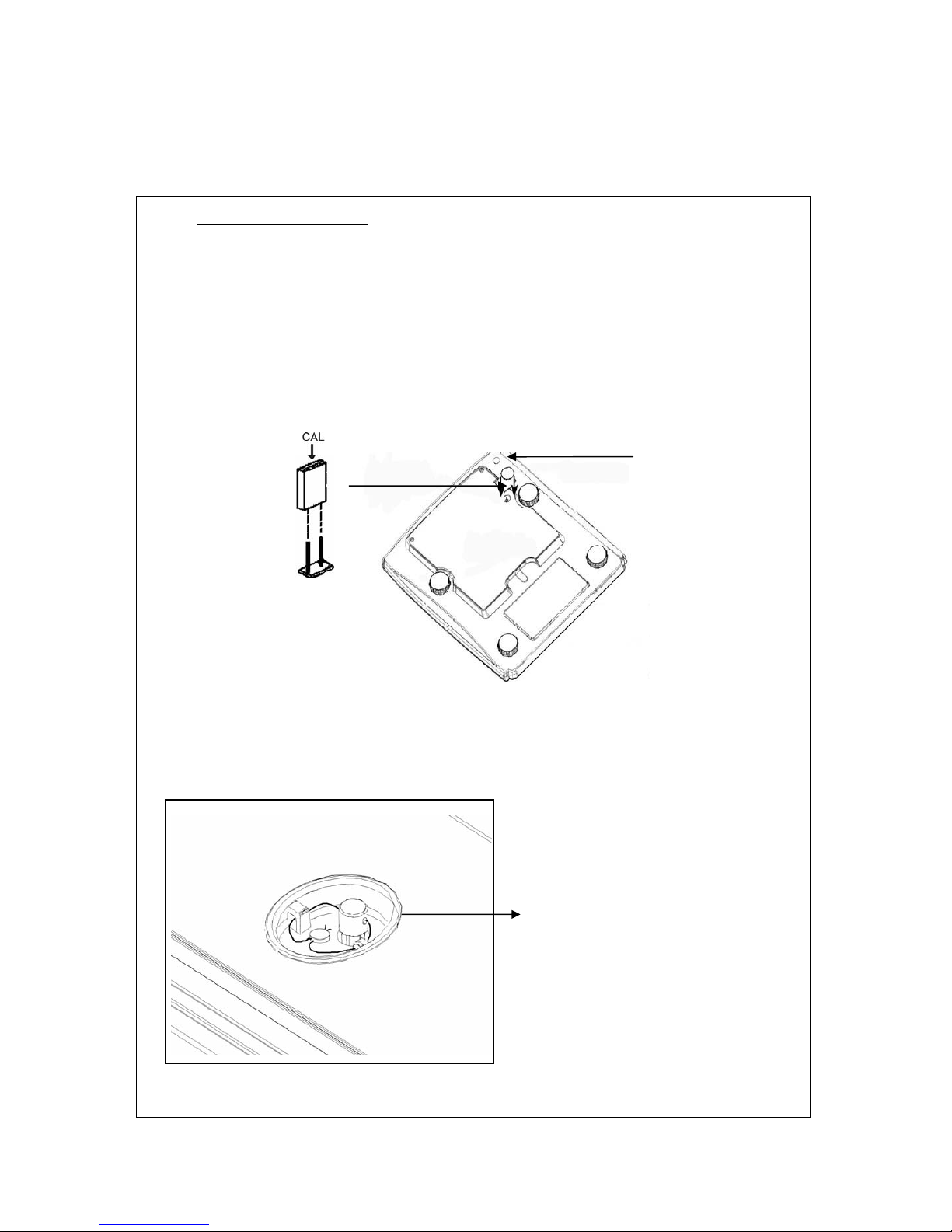
3.1 JUMPER AND SEALS
1. Bottom of the balance
Access to conductor plate:
• Place your balance upside down
• Remove seal
• For verified balances, the jumper is on a pin
• For adjustment the jumper must be set on both pins
Position jumper for adjustment
2. Top of the balance
• Remove weighing plate
Position
of seal
Sealing by seal or by lead
seal
RPB-SH-e-0610 5
Page 6

3.2 CALIBRATION PROCEDURE
For verified balances calibration by means of a jumper is locked. In order to carry out
calibration the two contacts of the conductor plate must be shorted with a jumper in
K6 position (see chapt. 3.1).
If the hole is not provided in your scale, the security seal has to be broken to remove
the top cover and gain access to the main PCB. Replace the cover and install the
screws before starting the calibration.
Observe stable environmental conditions. A warming up time of approx. 10 minutes
is required for stabilization. Ensure that there are no objects on the weighing plate.
After the jumper has been placed in position K6, apply power to the scale.
During the self-test press the key.
The display will ask for a code number, “Pn - - - -“ on the Weight Display.
To carry out the calibration, enter the number “0000” then press . The display will
show “CAL F1” will be enabled. Press the key.
The display will show “UnloAd” asking you to remove any weight from the scale.
Press the key.
The display will tell you to add weight to the scale by showing “LoAd” “15” “kilo”
Add the weight shown, wait for stability then press the key.
The display will show “
SPAn” “PASS” if the calibration is OK.
Or it will show “SPAN” “FAIL” if calibration could not be completed correctly.
The scale will return to the parameter menu (“CAL F1”).
Return to weighing mode by pressing the
key.
Back to calibration process by pressing the key.
6 RPB-SH-e-0610
Page 7

4 SERVICE PARAMETERS
(Using “2003” to enter the service parameters)
After the jumper has been placed in position K6 (the two contacts of the conductor
plate must be shorted with a jumper, see chapt. 3.1), apply power to the scale.
During the self-test press the key.
The display will ask for a code number, “Pn - - - -“ on the Weight Display.
Enter the number “2003” when “Pn - - - -“ is displayed and then press .
The displays will show the first parameters, called “F1”. To select another parameter
press the key to advance through the parameters.
Press the key to enter a parameter.
To exit a parameter press the key.
The Weight Display window will show the word “CAL” and the Unit Price window will
show the parameter number.
When a parameter is entered by pressing the key, the displays will guide you
through the parameter selected and the options available.
The parameters available are:
F2 RES Resolution selection
F3 CAPA Select capacity
F4 0.00 Point Weight decimal point location
F5 Point 0.00 0.00 Unit Price/Price decimal point
F6 Init ZEro Initial Zero Range
F7 rE ZEro Re-Zero range
F8 SCSivE tArE Successive Tare Enable
F9 A/D counts Display the A/D counts
F10 roUnd Rounding off the Total Price
F1 CAL To enter the Calibration
RPB-SH-e-0610 7
Page 8

4.1 F1 – CALIBRATION
To enter the calibration parameter, press the key when “F1” is displayed.
The display will instruct you to remove any weight from the scale, “UnloAd”.
Press the key.
The display will tell you to add weight to the scale: “LoAd” “ 15” “kilo”.
Add the weight shown, wait for stability then press the
key.
The display will show “
SPAn” “PASS” if the calibration is OK. Or it will show “SPAn”
“FAIL” if calibration could not be completed correctly.
The scale will return to the parameter menu.
4.2 F2 – RESOLUTION
To enter this parameter, press the key when “F2” is shown.
The display will show the current resolution, either 3000 or 6000 or Dual Range.
Press the key to change the value.
Press to accept the displayed value.
NOTE: Only 3000 is allowed for the RPB scales.
8 RPB-SH-e-0610
Page 9

4.3 F3 – CAPACITY
To enter this parameter, press the key when “F3” is shown.
The display will show the current capacity in 6, 15 or 30 kilograms.
Press the key to change the value.
Press to accept the displayed value.
NOTE: The scale must be originally built for the capacity selected. The 6 kg unit
uses 10kg load cells, the 15 kilogram unit uses 20 kilogram load cells and the 30
kilogram unit uses 35 kilogram load cells.
4.4 F4 – WEIGHT DECIMAL POINT POSITION
To enter this parameter, press the key when “F4” is shown.
The display will show the current decimal point location in the Weight window.
Press the key to change the value and press to accept the value.
NOTE: Only certain positions are allowed for the RPB scales.
4.5 F5 – UNIT PRICE/TOTAL PRICE DECIMAL POINT LOCATION
To enter this parameter, press the
key when “F5” is shown.
The display will show the current decimal point location in the Unit Price and the
Total Price windows.
Press the
key to change the value.
Press to accept the displayed value.
NOTE: The units must match the currency used in the country. Normally 0.00
is shown.
RPB-SH-e-0610 9
Page 10

4.6 F6 – INITIAL ZERO RANGE
To enter this parameter, press the key when “F6” is shown.
The display will show the current initial zero range.
Press the key to change the value and press to accept the value.
NOTE: Only 10% is allowed for the RPB scales.
4.7 F7 – RE-ZERO RANGE
To enter this parameter, press the key when “F7” is shown.
The display will show the current re-zero range.
Press the key to change the value and press to accept the value.
NOTE: Only 2% is allowed for the RPB scales.
4.8 F8 – SUCCESSIVE TARE
To enter this parameter, press the key when “F8” is shown.
The display will show if the successive tare is on or off.
Press the key to change the value.
Press to accept the displayed value.
NOTE: Either option is allowed for the RPB scales.
10 RPB-SH-e-0610
Page 11

4.9 F9 – A/D COUNT
To enter this parameter, press the key when “F9” is shown.
This parameter allows you to view the A/D counts from the internal A/D converter.
This can be an aid to service.
Press the key to return to the PARAMETER menu.
Press the key to return to weighing.
Ranges allotted at zero is 30,000-90,000 (approx.)
Ranges allotted at full capacity is 400,000 (approx.)
NOTE: To secure the scale after calibration, it is necessary to remove the
jumper placed at position K6 and re-seal the scale.
4.10 F10 – ROUNDING OFF THE TOTAL PRICE
This parameter allows you to set the value to 1 or 5 for rounding off the least
significant digit of the Total Price. For example, if the value is set to 1, the Total Price
will remain as 12.47 for the original value of 12.47 and if it is set to 5, the Total Price
will be rounded off to 12.45 instead of 12.47.
To enter this parameter, press the key when “F10” is shown.
The display will show the current settings.
Press the
key to change the value and press to accept the value.
Press
to return to the PARAMETER menu.
Press to return to weighing.
RPB-SH-e-0610 11
Page 12

5 WIRING DIAGRAM
12 RPB-SH-e-0610
Page 13

6 MECHANICAL ASSEMBLY
6.1 EXPLODED DRAWING
RPB-SH-e-0610 13
Page 14

6.2 LIST OF MECHANICAL ASSEMBLY
26 front display overlay 1
25 front keyboard 1
24 screw 1
23 washer 4
22 tapping screw 4
21 washer 4
20 main PCBA 1
19 screw 5
18 screw 1
17 washer 4
16 battery cover 1
15 power switch 1
14 support feet 4
13 bottom cover 1
12 rechargeable battery 1
11 rear display PCBA 1
10 the load cell lower supporter 1
9 the load cell 1
8 the load cell upper supporter 1
7 washer 2
6 screw 2
5 front display PCBA 1
4 upper cover 1
3 rear display overlay 1
2 ABS pan 1
1 SST pan 1
14 RPB-SH-e-0610
Page 15

7 SCHEMATICS AND COMPONENTS LAYOUT
7.1 FRONT DISPLAY SCHEMATIC
RPB-SH-e-0610 15
Page 16

7.2 MAIN PCB ASSEMBLY
16 RPB-SH-e-0610
Page 17

7.3 MAIN SCHEMATIC LAYOUT
RPB-SH-e-0610 17
Page 18

7.4 PILLAR DISPLAY SCHEMATIC
18 RPB-SH-e-0610
Page 19

7.5 REAR DISPLAY SCHEMATIC
RPB-SH-e-0610 19
 Loading...