

Page 1
KERN & Sohn GmbH
Ziegelei 1
D-72336 Balingen
E-mail: info@kern-sohn.com
Tel: +49-[0]7433- 9933-0
Fax: +49-[0]7433-9933-149
Internet: www.kern-sohn.com
User instructions
Metallurgical inverted microscope
KERN OLM-1
OLM 171
Version 1.0
12/2016
OLM-1-BA-e-1610
Page 2

Page 3

GB
KERN OLM-1
Version 1.0 12/2016
User instructions
Metallurgical inverted microscope
Table of contents
1 Before use .................................................................................... 3
1.1 General notes ............................................................................................................................ 3
1.2 Notes on the electrical system ................................................................................................ 3
1.3 Storage ...................................................................................................................................... 4
1.4 Maintenance and cleaning ....................................................................................................... 5
2 Nomenclature ............................................................................... 6
3 Technical data / Features ............................................................ 8
4 Assembly .................................................................................... 10
4.1 Reflected light unit ................................................................................................................. 11
4.2 Objectives ............................................................................................................................... 12
4.3 Eyepieces ................................................................................................................................ 13
4.4 Specimen stage ...................................................................................................................... 13
5 Operation .................................................................................... 14
5.1 Getting started ........................................................................................................................ 14
5.2 (Pre-) focussing ...................................................................................................................... 15
5.3 Adjusting the interpupillary distance ................................................................................... 16
5.4 Dioptre adjustment ................................................................................................................. 16
5.5 Adjusting the magnification .................................................................................................. 17
5.6 Using eye cups ....................................................................................................................... 18
5.7 Adjusting the illumination ..................................................................................................... 19
6 Changing the bulb ..................................................................... 20
7 Changing the fuse ...................................................................... 21
8 Using optional accessories ....................................................... 22
8.1 Camera connection ................................................................................................................ 22
9 Trouble shooting ........................................................................ 23
10 Service ........................................................................................ 25
11 Disposal ...................................................................................... 25
12 Further information .................................................................... 25
OLM-1-BA-e-1610 2
Page 4

1 Before use
1.1 General notes
You must open the packaging carefully, to make sure that none of the accessories in
the packaging fall on the floor and get broken.
In general, microscopes should always be handled carefully because they are
sensitive precision instruments. When using or transporting the microscope it is
particularly important to avoid abrupt movements, as this may damage the optical
components.
You should also avoid getting dirt or finger prints on the lens surface, because in
most cases this will reduce image clarity.
To maintain the performance of the microscope, it must never be disassembled. So
components such as lenses and other optical elements should be left as they were
before use. Also the electrical parts on the rear and base of the device must not be
tampered with, as in this area there is an additional risk of triggering an electric
shock.
1.2 Notes on the electrical system
Before connecting to a mains power supply, you must make sure that you are using
the correct input voltage. The information to select the correct mains cable is located
on the device, on the rear of the product directly above the connection socket. You
must comply with this information. If you do not comply with these specifications, then
fires or other damage to the device could occur.
The main switch must also be switched off before the mains cable is connected. In
this way you will avoid triggering an electric shock.
If you are using an extension cable, then the mains cable you use must be earthed.
If the original fuse should blow, it must only be replaced by an appropriate fuse.
Suitable replacement fuses are included with the delivery.
When carrying out any procedures whereby you come into contact with the electrical
system of the device, such as, for example, changing the bulb or fuse, only carry out
these procedures when the power is disconnected.
3 OLM-1-BA-e-1610
Page 5

Under no circumstances should you touch the integrated halogen bulb either during
operation or directly after use. These bulbs produce significant heat and therefore
there is a risk that the user could be severely burnt. So before handling the bulbs,
you must check that they have cooled down.
The microscope housing, on the other hand, is constructed so that no significant heat
radiation emanates from the device and that there is absolutely no risk of the user
burning themselves from the housing outer surfaces.
1.3 Storage
You should ensure that the device is not exposed to direct sunlight, temperatures
which are too high or too low, vibrations, dust or a high level of humidity.
The ideal temperature range is between 0 and 40°C and a relative humidity of 85%
should not be exceeded.
The device should always be located on a rigid, smooth, horizontal surface.
When the microscope is not being used, you should cover it with the enclosed dust
protective cover. When doing this, the power supply is stopped by switching off at the
main switch and unplugging the mains cable. If the eyepieces are being stored
separately, the protective caps must be fitted to the tube connectors. In most cases,
if dust and dirt gets inside the optical unit of a microscope this can cause irreversible
errors or damage.
The best way to store accessories which consist of optical elements, such as, for
example, eyepieces and objectives, is in a dry box with desiccant.
OLM-1-BA-e-1610 4
Page 6

1.4 Maintenance and cleaning
In any event, the device must be kept clean and dusted regularly.
If any moisture should be occur, before you wipe down the device you must ensure
that the mains power is switched off.
When glass components become dirty, the best way to clean them is to wipe them
gently with a lint-free cloth.
To wipe oil stains or finger prints off the lens surface, moisten the lint free cloth with a
mixture of ether and alcohol (70 / 30 ratio) and use this to clean the lens.
You must be careful when handling ether and alcohol, as these are highly flammable
substances. You must therefore keep it away from naked flames and electrical
devices which can be switched on and off, and only use it in well-ventilated rooms.
However organic solutions of this type should not be used to clean other components
of the device. This could lead to damage to the paint finish. To do this, it is sufficient
to use a neutral cleaning product.
You could also use the following cleaning products to clean the optical components:
Special cleaner for optical lenses
Special optical cleaning cloths
Bellows
Brush
When handled correctly and checked regularly, the microscope should give many
years of efficient service.
Should repairs still be necessary, please contact your KERN dealer or our Technical
Department.
5 OLM-1-BA-e-1610
Page 7
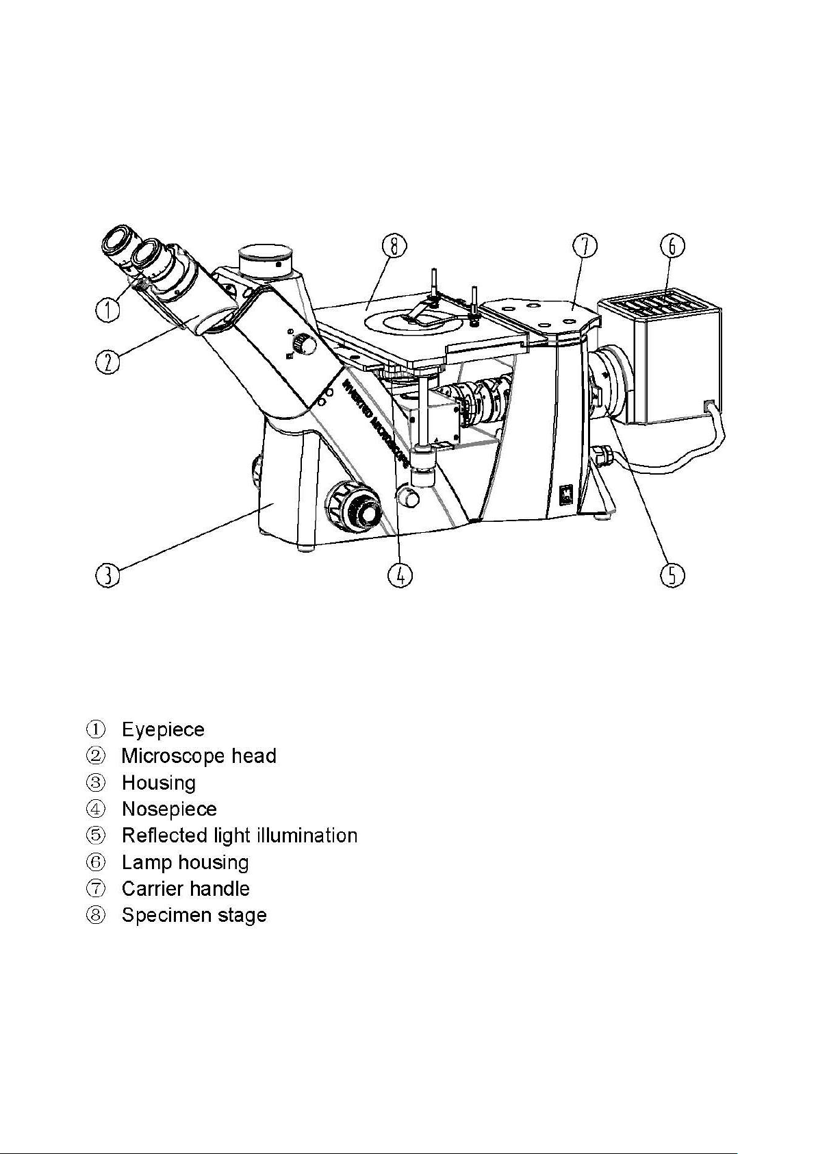
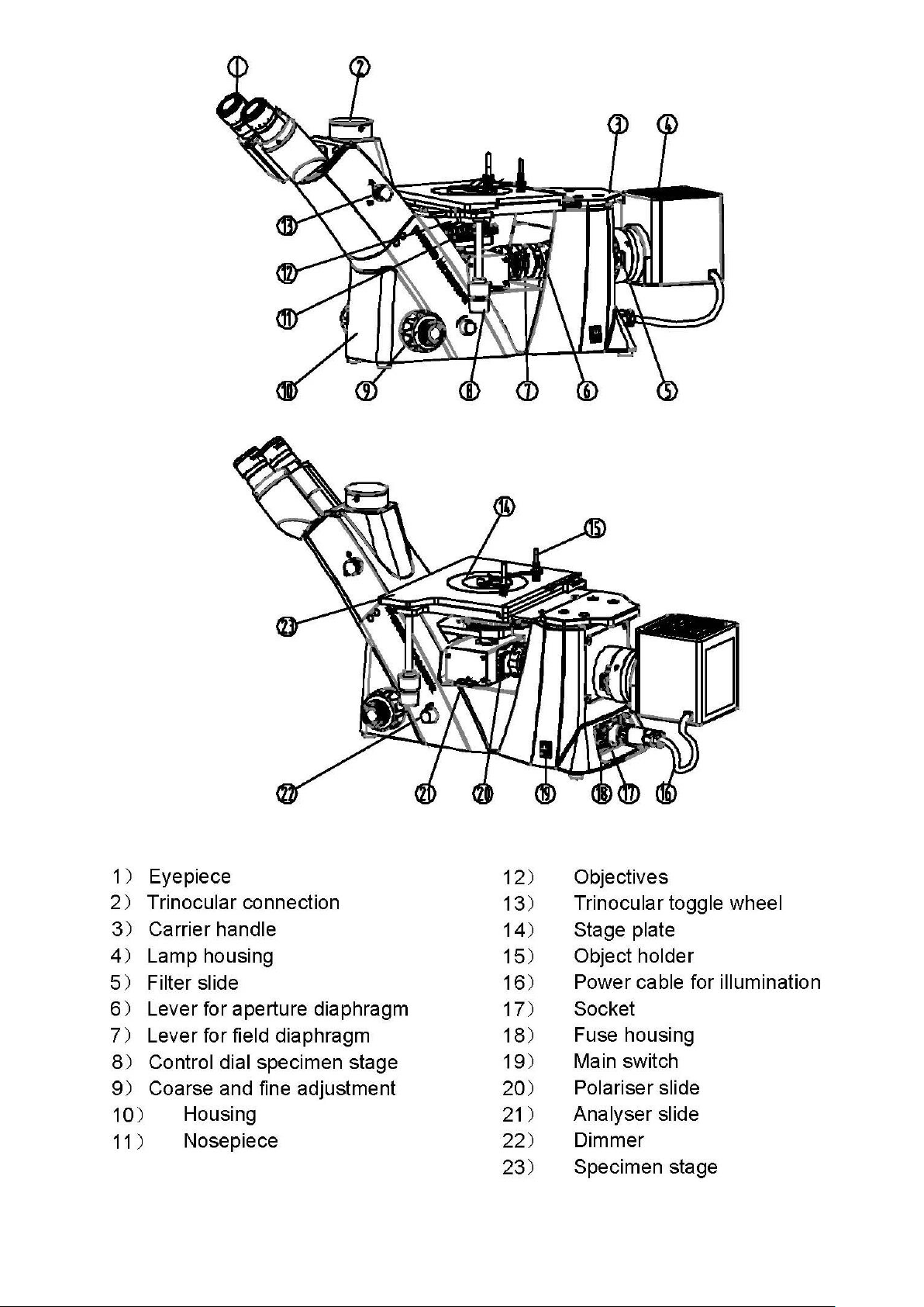
2 Nomenclature
OLM-1-BA-e-1610 6
Page 8
7 OLM-1-BA-e-1610
Page 9

3 Technical data / Features
Product dimension:
271×379×747 mm
Packing dimensions:
660x590x325 mm
Net weight:
12,5 kg
Gross weight:
17 kg
Input voltage:
AC 100-240V, 50-60Hz
Output voltage:
DC 1,2-6V
Fuse:
2A 5x20mm
OLM-1-BA-e-1610 8
Page 10

9 OLM-1-BA-e-1610
Page 11

4 Assembly
OLM-1-BA-e-1610 10
Page 12

4.1 Reflected light unit
At first you have to unite the lamp housing [1] and the reflected light unit on their
connection points. After that the connection has to be fixated by two Allen screws,
which are attached to the connection point [2]. When doing this, you should always
make sure that you do not touch the lenses with your bare fingers and that no dust
enters the apertures.
Afterwards you must establish the electrical connection between the lamp housing
and the integrated power supply unit of the microscope. The plug of the connection
cable [3] has to be installed to the according socket on the rear of the microscope
housing. Please do also use the screw lock on the plug.
Now the slides for analyser, polariser and colour filter can be attached to the
appropriate slots.
Refer to page 7:
Analyser slide / bears the inscription „A“: 21)
Polariser slide / bears the inscription „P“: 20)
Colour filter slide / the supplied blue filter needs to be previously inserted: 5)
11 OLM-1-BA-e-1610
Page 13

4.2 Objectives
The nosepiece must be in its lowest position so that the objectives [1] can be
screwed into it. You can then pass the objectives through the opening of the
specimen stage and screw them into the nosepiece, so that when you turn the
nosepiece in a clockwise direction, the objective with the next strongest magnification
appears. You must make sure that you do not touch the lenses with your bare fingers
and that no dust enters the apertures.
To the screw locations which are not filled with an objective [2], you must attach the
protective cap.
OLM-1-BA-e-1610 12
Page 14

4.3 Eyepieces
You must always use eyepieces with the
same magnification for both eyes. These
are simply placed onto the tube
connectors, once you have first removed
the plastic protective caps. There is a way
of fixing them by an Allen screw [1] for
each eyepiece that is located on the tube
connector (see illustration). You should
always make sure that you do not touch
the lenses with your bare fingers and that
no dust enters the apertures.
4.4 Specimen stage
The supplied stage plate [1] needs to be fitted to the opening of the specimen stage,
in order to get a support area for relatively small observation objects and to protect
the objectives which are located underneath.
Furthermore you can attach an object holder to one of the threads on stage surface
(see page 7 > [15]).
For the connection of a camera, please see Chapter 8 Use of optional
accessories.
13 OLM-1-BA-e-1610
Page 15

5 Operation
5.1 Getting started
The very first step is to establish a power connection using the mains plug. You
should first adjust the dimmer to a low level, so that when you look through the
eyepiece for the first time, your eyes are not immediately subject to a high level of
light. You can now switch on the lighting using the main switch.
The next step is to place a sample on the specimen stage (see left illustration [1]).
For the models of the OLM-1 series you can fixate the samples on the stage with
help of the object holder.
To move the part to be observed of the sample into the beam path, you must use the
adjustment wheels on the right of the specimen stage. For centre-adjusting the
specimen stage you can take the according markings on the side of the stage as
points of reference (see right illustration).
OLM-1-BA-e-1610 14
Page 16

5.2 (Pre-) focussing
When you are observing an object, you must have the correct distance to the
objective to achieve a sharp image.
In order to find this distance at the beginning (without other default settings of the
microscope) place the objective with the lowest magnification in the beam path, look
through the right eyepiece with the right eye and turn it slowly using the coarse
adjustment knob.
The simplest way of doing this would be to first raise the nosepiece (using the coarse
adjustment knob) to the top position and then lower it slowly. As soon as an image is
recognisable (no matter how sharp), then you should only adjust the focus using the
fine adjustment knob.
Adjusting the torque of the coarse and fine adjustment knob
Next to the left adjustment wheel for the coarse and fine adjustment knob there is a
ring (see illustration [1]) which you can use to alter the torque of these wheels.
Turning it in a clockwise direction reduces the torque and turning it in an anticlockwise direction increases it.
On one hand, this function can help to make it easier to adjust the focus and on the
other hand it can prevent the nosepiece from slipping down unintentionally.
Important:
In order to avoid damaging to the focussing system, the left and right adjustment
wheels for the coarse and fine adjustment knob must never be rotated at the same
time in opposite directions.
15 OLM-1-BA-e-1610
Page 17

5.3 Adjusting the interpupillary distance
With binocular viewing, the interpupillary distance
must be adjusted accurately for each user, in order
to achieve a clear image of the object.
While you are looking through the eyepieces, use
your hands to hold the righthand and lefthand tube
housing firmly. By pulling them apart or pushing them
together, you can either increase or reduce the
interpupillary distance (see illustration). As soon as
the field of views of the lefthand and righthand
eyepieces completely overlap each other, i.e. they combine to form a circular image,
then the interpupillary distance is set correctly.
5.4 Dioptre adjustment
The eye strengths of each eye of the microscope user can often be slightly different,
which in daily life has no consequences. But when using a microscope this can
cause problems in achieving precise focussing.
You can use a mechanism on both tube connectors (dioptre adjustment rings) to
compensate for this as follows.
1. Put the right dioptre adjustment ring to position 0.
2. Look through the right eyepiece with the right eye and bring the object into focus
by using the coarse and fine adjustment knob.
3. Then look through the left eyepiece with the left eye and use the lefthand dioptre
adjustment ring to focus the image.
To do this, you just need to turn the ring in both directions (see illustration), to find
out where the image is at its most focussed.
OLM-1-BA-e-1610 16
Page 18

5.5 Adjusting the magnification
After prefocussing has been carried out using the objective with the lowest
magnification (see section 5.2) you can then adjust the overall magnification using
the nosepiece, as necessary. By turning the nosepiece you can bring any one of the
four other objectives into the beam path.
When adjusting the nosepiece, you must take the following points into account:
- The required objective must be properly locked in place at all times.
- The nosepiece should not be rotated by holding individual objectives. You should
use the black ring below the objectives.
- When rotating the nosepiece you must always make sure that the objective which
is about to be positioned in the beam path does not touch the stage plate. This
can lead to significant damage to the objective lens.
We recommend that you always check from the side to make sure that there is
sufficient leeway. If this should not be the case, the nosepiece must be lowered
accordingly.
If you have focussed the object to be observed for a specific magnification, then if
you select the objective with the next greatest magnification, the object will be slightly
out of focus. Use the fine adjustment knob to make a slight adjustment and restore
the focus.
17 OLM-1-BA-e-1610
Page 19
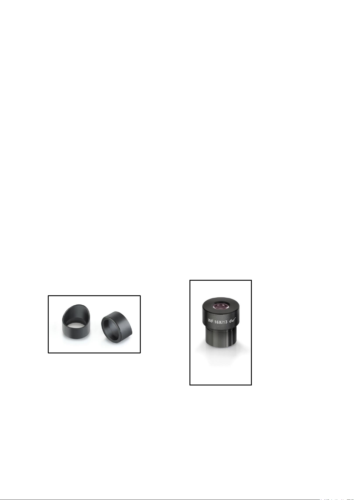
5.6 Using eye cups
The eye cups supplied with the microscope can basically be used at all times, as
they screen out intrusive light, which is reflected from light sources from the
environment onto the eyepiece, and the result is better image quality.
But primarily, if eyepieces with a high eye point (particularly suitable for those who
wear glasses) are used, then it may also be useful for users who don’t wear glasses,
to fit the eye cups to the eyepieces.
These special eyepieces are also called High Eye Point eyepieces. They can be
identified by the glasses symbol on the side. They are also marked in the item
description by an additional “H” (example: HSWF 10x Ø 23 mm).
When fitting the eye cups, make sure that the dioptre setting is not moved. We would
therefore advise that you hold the dioptre compensation ring on an eyepiece with one
hand while you fit the eye cup with the other.
Before using the microscope, users who wear glasses must remove the eye cups,
which you may find on High Eye Point eyepieces.
As the eye cups are made of rubber, you must be aware that when you are using
them, they can become slightly dirty through grease residues. In order to maintain
hygiene, we would therefore recommend that you clean the eye cups regularly (e.g.
with a damp cloth).
Eye cups
High Eye Point eyepiece
(identified by the glasses symbol)
OLM-1-BA-e-1610 18
Page 20

5.7 Adjusting the illumination
To make sure that perfect image results are achieved during microscopic
observation, it is important that the direction of light of the microscope is optimised.
The following components of the reflected light unit can be adjusted according to the
application requirements.
Field diaphragm and aperture diaphragm
(See page 7 > [6] + [7])
The field diaphragm is responsible for the optimum illumination of the field of view. It
is able to reduce undesired stray light.
The aperture diaphragm is used to find the very best compromise between contrast
and resolution for the microscopic image.
To open and close these diaphragms you have to operate the levers located at the
top of the reflected light unit.
Colour filter
(See page 7 > [5])
The colour filter slide has one round aperture. If needed, the supplied blue filter has
to be inserted into this aperture. Subsequently the filter slide must be put into the slot
on the connection point between the reflected light unit and the lamp housing.
Polarising unit (Analyser / Polariser)
(See page 7 > [20] + [21])
The microscopes from the OLM-1 series provide the possibility to apply the
contrasting method of polarised light. For this purpose the analyser and polariser
(both of them are included with the scope of delivery) are used.
In order to bring the analyser into the beam path you must attach the analyser slide
to the slot, located underneath the nosepiece. Both the slide and the slot bear the
inscription “A”.
Next to the field and aperture diaphragm the slot for the polariser is located. Both the
slide and the slot bear the inscription “P”. The integrated wheel on the polariser slide
is facing out after attaching it to the slot. With the wheel you can control the required
alignment of the polariser.
19 OLM-1-BA-e-1610
Page 21
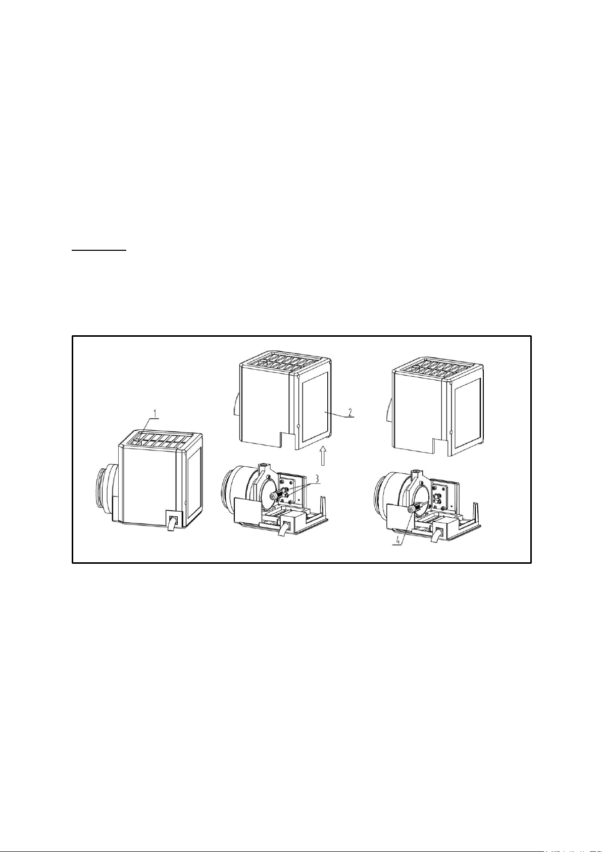
6 Changing the bulb
You must not attempt to change the bulb immediately after the microscope has been
used, as the bulb will still be hot and so there is a risk that the user could be burnt.
Before changing the bulb the device must be switched off and unplugged.
To change the bulb the cover of the lamp housing [2] needs to be removed.
Therefore you previously have to loosen the appropriate Allen screw [1]. Now the
defective bulb can be pulled out of the socket and be replaced with a new one [4].
We recommend that here you should also test again, to check that heat is no longer
being produced. After the cover has been reattached and fixated, the bulb
replacement procedure is complete.
Important:
When fitting the new bulb into the socket, it must only be handled with sterile gloves
or using the bulb packaging film. Grease and dust residue can have a negative effect
on the light quality and service life.
OLM-1-BA-e-1610 20
Page 22
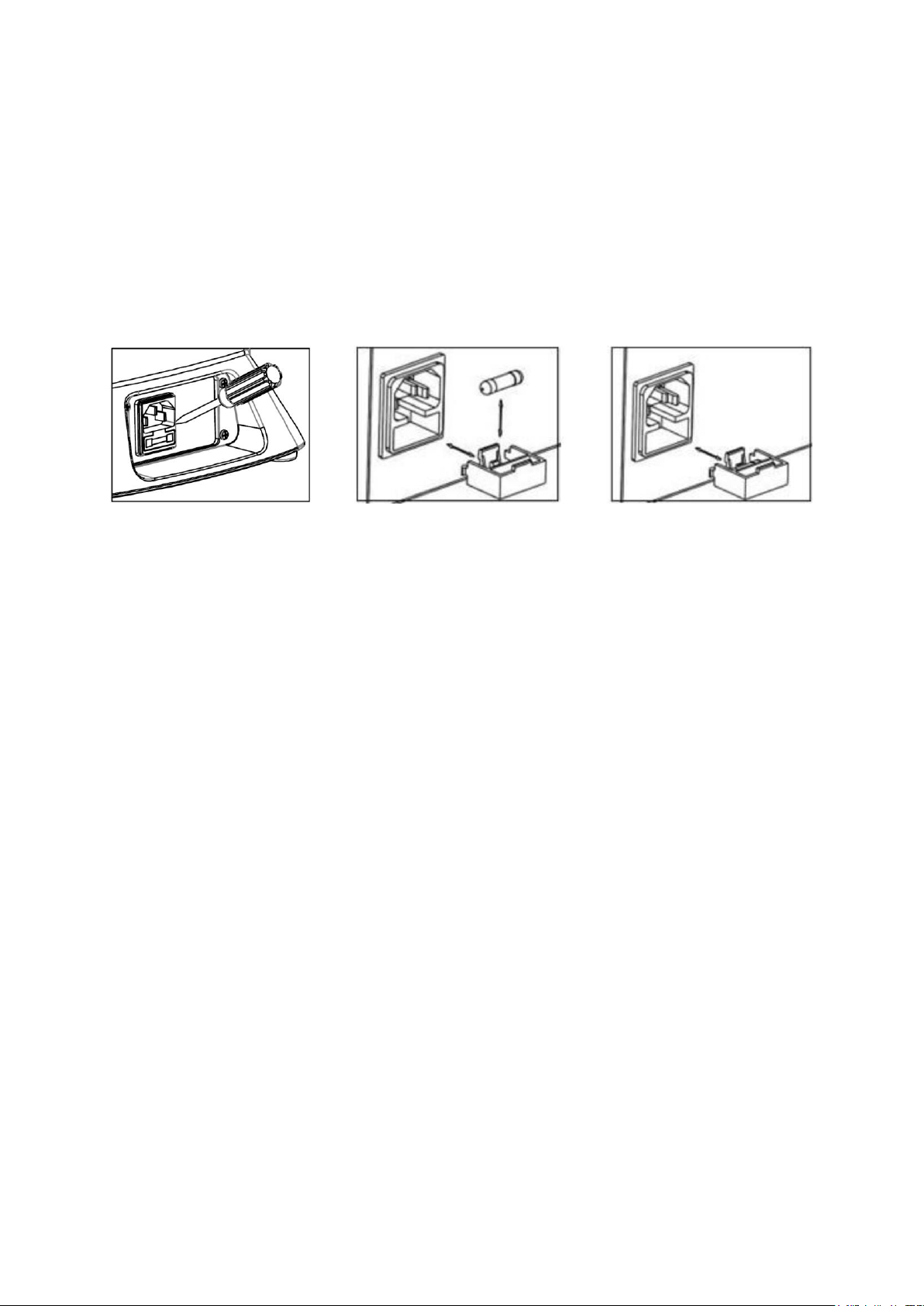
7 Changing the fuse
The fuse housing is on the rear of the microscope below the mains power supply
socket. With the device switched off and unplugged, you can pull out the housing.
When doing this, it is helpful to use a screwdriver or similar tool (see left illustration).
The defective fuse can be removed from its housing and be replaced with a new one
(see middle illustration).
After that, you just need to insert the fuse housing back into the insertion point below
the mains power supply socket (see right illustration).
21 OLM-1-BA-e-1610
Page 23
8 Using optional accessories
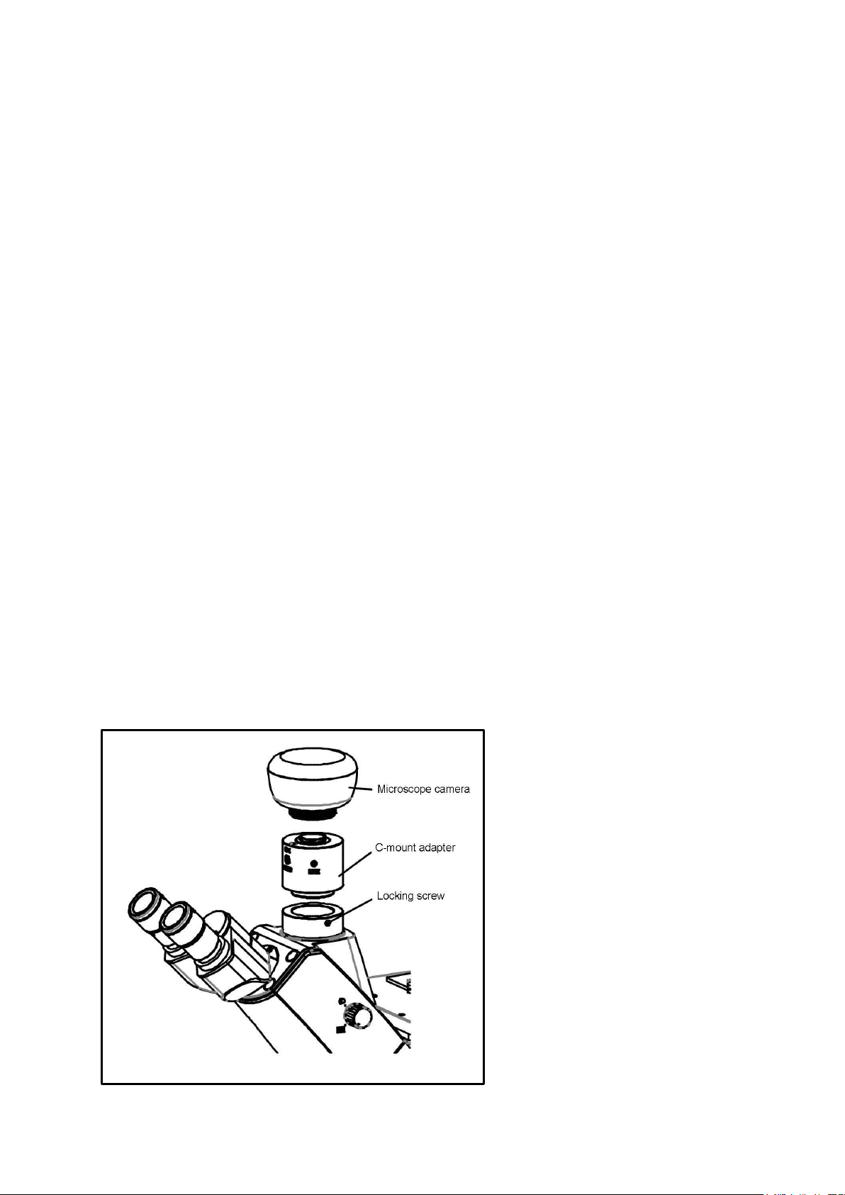
8.1 Camera connection
Due to the trinocular tube it is possible to connect microscope cameras to the device,
in order to digitally record images or sequences of images of an object being
observed.
After the plastic cover has been removed from the camera adapter connector on the
top of the microscope head, then a suitable adapter must be fitted.
In general there are two C-mount adapters available for this (1x and 0.5x
magnification, see Chapter 3 Features). After fitting one of these adapters it can be
fixed with the locking screw. A camera which has a C-mount thread is then screwed
on top of the adapter.
We recommend that you first adjust the field of view using the eyepieces on the
device for the existing requirements, and then carry out the observation using the
microscope camera (i.e. using the PC screen which is connected).
To do this, the trinocular wheel on the righthand side of the microscope head must be
set to the position “Camera”. The light from the microscope lighting is deflected so
that it is completely in the beam path for the camera, which causes a dark field of
view in the eyepieces. This means that it is not possible to simultaneously observe by
the eyepieces and PC screen.
For C-mount adapters, which have their own integrated magnification, the image
which is shown on the camera connected to the device can often have a different
level of focus compared with the image on the eyepiece.
In order to be able to bring both images into focus, the focus can be adjusted by
those adapters.
OLM-1-BA-e-1610 22
Page 24

9 Trouble shooting
Problem
Possible causes
The bulb does not light
The mains plug is not correctly plugged in
There is no power at the socket
Defective bulb
Defective fuse
The bulb blows immediately
The specified bulb or fuse has not been used
The field of view is dark
The aperture diaphragm and/or field
diaphragm are not opened wide enough
The selector switch for the beam path is set
to “Camera”
The condenser is not correctly centred
You cannot adjust the brightness
The brightness control has been set
incorrectly
The condenser has not been correctly
centred
The field of view is dark or is not
correctly
illuminated
The objective is not positioned correctly on
the beam path
The selector switch for the beam path is
between two settings
The nosepiece is not correctly fitted
An objective is being used which doesn’t
match the lighting area of the condenser
The condenser has not been correctly
centred
The field diaphragm is closed too tightly
The bulb is not correctly fitted
The field of view of one eye does not
match that of the other eye
The interpupillary distance is not correctly
adjusted
Dioptre setting has not been carried out
correctly
Different eyepieces are used for the
righthand and lefthand side
The eyes are not used to using a microscope
23 OLM-1-BA-e-1610
Page 25

Problem
Possible causes
Blurred details
Bad image
Bad contrast
Vignetted field of view
The aperture diaphragm is not opened wide
enough
The objective does not belong to this
microscope
The front lens of the objective is dirty
The condenser is not correctly centred
Dirt / dust on the objective
Dirt /dust on the front lens of the condenser
Dirt or dust in the field of view
Dirt / dust on the eyepieces
Dirt / dust on the front lens of the condenser
Dirt / dust on the object
One side of the image is blurred
The stage was not correctly fitted
The objective is not positioned correctly on
the beam path
The nosepiece is not correctly fitted
The image flickers
The nosepiece is not correctly fitted
The objective is not positioned correctly on
the beam path
The condenser has not been correctly
centred
The coarse adjustment knob is difficult to
turn
The rotational resistance brake is too
tight
The angle table is blocked by a
solid body
The stage moves down on its own
The fine adjustment knob moves on its
own
The rotational resistance brake is not tight
enough
When you move the table, the image
becomes blurred
The stage was not correctly fitted
OLM-1-BA-e-1610 24
Page 26

10 Service
All language versions contain a non-binding translation.
The original German document is the binding version.
Internationale Temperatur Korrektur Tabelle für °Brix (% Zuckergradient)
Das Ergebnis um die folgenden Werte korrigieren (Refraktometer muss korrekt kalibriert sein bei 20°C)
Reading °Brix
0.0 5.0 10.0 15.0 20.0 25.0 30.0 35.0 40.0 45.0 50.0 55.0 60.0 65.0 70.0 75.0 80.0 85.0
10.0 -0.53 -0.56 -0. 59 -0.62 -0.65 -0.67 -0. 69 -0.71 -0.72 -0.73 -0. 74 -0.75 -0.75 -0.75 -0. 75 -0.75 -0.74 -0.73
11.0 -0.49 -0.52 -0. 54 -0.57 -0.59 -0.61 -0. 63 -0.64 -0.65 -0.66 -0. 67 -0.68 -0.68 -0.68 -0. 68 -0.67 -0.67 -0.66
12.0 -0.44 -0.47 -0. 49 -0.51 -0.53 -0.55 -0. 56 -0.57 -0.58 -0.59 -0. 60 -0.60 -0.61 -0.61 -0. 60 -0.60 -0.60 -0.59
13.0 -0.40 -0.41 -0. 43 -0.45 -0.47 -0.48 -0. 50 -0.51 -0.52 -0.52 -0. 53 -0.53 -0.53 -0.53 -0. 53 -0.53 -0.52 -0.52
14.0 -0.34 -0.36 -0. 38 -0.39 -0.40 -0.42 -0. 43 -0.44 -0.44 -0.45 -0. 45 -0.46 -0.46 -0.46 -0. 46 -0.45 -0.45 -0.44
15.0 -0.29 -0.31 -0. 32 -0.33 -0.34 -0.35 -0. 36 -0.37 -0.37 -0.38 -0. 38 -0.38 -0.38 -0.38 -0. 38 -0.38 -0.37 -0.37
16.0 -0.24 -0.25 -0. 26 -0.27 -0.28 -0.28 -0. 29 -0.30 -0.30 -0.30 -0. 31 -0.31 -0.31 -0.31 -0. 31 -0.30 -0.30 -0.30
17.0 -0.18 -0.19 -0. 20 -0.20 -0.21 -0.21 -0. 22 -0.22 -0.23 -0.23 -0. 23 -0.23 -0.23 -0.23 -0. 23 -0.23 -0.23 -0.22
18.0 -0.12 -0.13 -0. 13 -0.14 -0.14 -0.14 -0. 15 -0.15 -0.15 -0.15 -0. 15 -0.15 -0.15 -0.15 -0. 15 -0.15 -0.15 -0.15
19.0 -0.06 -0.06 -0. 07 -0.07 -0.07 -0.07 -0. 07 -0.08 -0.08 -0.08 -0. 08 -0.08 -0.08 -0.08 -0. 08 -0.08 -0.08 -0.07
20.0 0.00 0. 00 0.00 0. 00 0.00 0. 00 0.00 0. 00 0.00 0. 00 0.00 0. 00 0.00 0. 00 0.00 0. 00 0.00 0. 00
21.0 0.06 0. 07 0.07 0. 07 0.07 0. 07 0.08 0. 08 0.08 0. 08 0.08 0. 08 0.08 0. 08 0.08 0. 08 0.08 0. 07
22.0 0.13 0. 14 0.14 0. 14 0.15 0. 15 0.15 0. 15 0.16 0. 16 0.16 0. 16 0.16 0. 16 0.15 0. 15 0.15 0. 15
23.0 0.20 0. 21 0.21 0. 22 0.22 0. 23 0.23 0. 23 0.23 0. 24 0.24 0. 24 0.24 0. 23 0.23 0. 23 0.23 0. 22
24.0 0.27 0. 28 0.29 0. 29 0.30 0. 30 0.31 0. 31 0.31 0. 32 0.32 0. 32 0.32 0. 31 0.31 0. 31 0.30 0. 30
25.0 0.34 0. 35 0.36 0. 37 0.38 0. 38 0.39 0. 39 0.40 0. 40 0.40 0. 40 0.40 0. 39 0.39 0. 39 0.38 0. 37
26.0 0.42 0. 43 0.44 0. 45 0.46 0. 46 0.47 0. 47 0.48 0. 48 0.48 0. 48 0.48 0. 47 0.47 0. 46 0.46 0. 46
27.0 0.50 0. 51 0.52 0. 53 0.54 0. 55 0.55 0. 56 0.56 0. 56 0.56 0. 56 0.56 0. 55 0.55 0. 54 0.53 0. 52
28.0 0.58 0. 59 0.60 0. 61 0.62 0. 63 0.64 0. 64 0.64 0. 65 0.65 0. 64 0.64 0. 64 0.63 0. 62 0.61 0. 60
29.0 0.66 0. 67 0.68 0. 69 0.70 0. 71 0.72 0. 73 0.73 0. 73 0.73 0. 73 0.72 0. 72 0.71 0. 70 0.69 0. 68
30.0 0.74 0. 75 0.77 0. 78 0.79 0. 80 0.81 0. 81 0.81 0. 82 0.81 0. 81 0.81 0. 80 0.79 0. 78 0.77 0. 75
Temperatur °C
If, after studying the user manual, you still have questions about commissioning or
using the microscope, or if unforeseen problems should arise, please get in touch
with your dealer. The device may only be opened by trained service engineers who
have been authorised by KERN.
11 Disposal
The packaging is made of environmentally-friendly materials, which you can dispose
of at your local recycling centre. Disposal of the storage box and device must be
carried out by the operator in accordance with all national or regional laws in force in
the location of use.
12 Further information
The illustrations may differ slightly from the product.
The descriptions and illustrations in this user manual are subject to change without
notice. Further developments on the device may lead to these changes.
25 OLM-1-BA-e-1610
Page 27

Notes
OLM-1-BA-e-1610 26
 Loading...