

Page 1

E
KERN VC
Version 1.2 01/2002
Operating instructions
Electronic counting balance
Table of contents
1 Technical data 21
1.1 KERN VC Electronic counting balance 21
2 Installation of the balance 22
2.1 Unpacking and package volume 22
2.2 Installation 22
3 Power supply 22
3.1 Power connection 22
3.2 Battery operation 22
4 Controls 23
4.1 Overview of displays and indicators 23
4.2 Overview of the keypad 24
5 Adjustments 25
5.1 Requirements: 25
5.2 Adjustment procedure 26
6 Control functions 27
6.1 Turning the balance on and off 27
6.2 Zeroing the balance 27
6.3 Taring 28
6.4 Manual tare 28
6.5 Parts counting 29
6.5.1 Known reference weight 30
6.5.2 Clearing the reference quantity 30
6.5.3 Storing the reference weight with the Preset key 31
6.6 Displaying the gross weight 31
6.7 Totalling 32
6.7.1 Clear stored values 33
6.7.2 Automatic shutoff 33
7 Important information 34
8 Minor breakdown 35
9 Declaration of Conformity 36
10 Safety seal for calibration 37
VC-BA-defsin-0212 20
Page 2

1 Technical data
1.1 KERN VC Electronic counting balance
KERN VC 3K1M VC 6K2M VC 15K5M VC 30K10M
Readout 1 g 2 g 5 g 10 g
Weighing range 3000 g 6000 g 15000 g 30000 g
Taring range (subtractive) 3000 g 6000 g 15000 g 30000 g
Min. piece weight at parts
counting
0,1 g 0,2 g 0,5 g 1 g
Adjusting weight
(not included) (clase)
3 kg (M1) 6 kg (M1) 15 kg (M1) 30 kg (M1)
Operating temperature - 10° C .... +40° C
Air humidity +15° C .... +85° C
Case (W x D x H) mm 343 x 367 x 119
Weighing plate mm 330 x 245
Weight kg (net) 4,4
VC-BA-defsin-0212
21
Page 3

2 Installation of the balance
2.1 Unpacking and package volume
Remove the balance from the packing materials carefully, take off the plastic cover and set
up the balance at the work site.
Keep all packing materials for future transport of the balance.
Standard accessories:
KERN VC
• Balance
• Weighing plate
• Power cord
• Instruction manual
2.2 Installation
• Put the weighing plate on the balance such that the holes match the pins on the
weighing plate.
• Set the balance on a stable surface.
• Make sure the balance is level by adjusting the foot screws until the air bubble
(at the left front of the body) is inside the circle.
3 Power supply
3.1 Power connection
Connect the adapter cord to the bottom of the balance.
Before plugging the cord into the socket, make sure that the voltage setting on the balance
is the same as the mains voltage.
3.2 Battery operation
Remove the battery cover at the bottom of the balance. Insert six (6) 1.5V batteries (size
D). Replace the battery cover.
If the balance will not be used for an extended period of time, remove the batteries and
store them separately. Battery acid leaks could damage the balance.
VC-BA-defsin-0212
22
Page 4

4 Controls
4.1 Overview of displays and indicators
A Weight display (in kg).
B Reference weight of 1000 units in kg.
(unit weight per 1000 units)
C Number of units
C
A
B
I II III IV V VI
I Zeroing indicator
IV Error indicator
Lights when the number of pieces is
insufficient (INSUFF)
II Net indicator
Lights when the tare value is valid.
V Recompute indicator (RECOMP)
Lights when the unit weight can be
recomputed by pressing the PCS
key.
III
Gross weight (GROSS)
Lights when the gross weight is
displayed.
VI Memory indicator (MEM)
Lights when there is data in the
totalling memory
VC-BA-defsin-0212
23
Page 5

4.2 Overview of the keypad
I
ON/OFF button
UNIT
WEIGHT
Specification of piece weight
by numeric input
1
Preadjust key (1, 2, ... 6)
Calls up stored reference weights
->0<-
Zeroing key
+
Plus key
Add when totalling
TARE
Tare key
-
Minus key
Subtract when totalling
Pcs
Parts key
*
Clear total key
Clears the memory values when
totalling
0 - 9
Numeric keys
NET/
GROSS
Net/gross weight key
Toggles between net and gross
weight
C
Clear key
VC-BA-defsin-0212
24
Page 6

5 Adjustments
The adjustment weights can be used to check and adjust balance precision at any time.
Adjustment weights can be acquired from KERN as an optional component. To decide
which adjustment weights are required, refer to Chapter 1 “Technical Data“.
5.1 Requirements:
Note! In calibrated apparatus, the adjustment switch can only be accessed by
destroying the safety seal. This would void the calibration.
• The adjustment switch is
located next to the screw
of the right front foot,
below the balance.
• Press with a long, blunt
object (e.g., tip of a
ballpoint pen) inside the
threaded hole.
• Turn the adjustment
switch on; the balance is
ready to be adjusted.
VC-BA-defsin-0212
25
Page 7

5.2 Adjustment procedure
Check that the surrounding conditions are stable, see “Important instructions“.
A short warm-up time of about 1 minute is recommended for stabilisation.
Display
kg kg/1000 Pcs
1. Requirements:
Turn the adjustment switch on;
see Chapter 5 "Adjustments".
DC688 VrX.XX S - ON
2. Press the {->0<-} key and hold down.
While holding the {->0<-} key, press the
8 7 1 5 keys in succession.
CAL 00
3. Make sure there is no weight on the weighing
plate. Press the {*} key.
- - - - -
4. The zero point is stored.
CAL SP will subsequently appear.
CAL SP
5. Place the necessary adjustment weight on the
weighing plate (see Chapter 1, “Technical
Data").
6. Enter the adjustment weight
(e.g., 10 for 10 kg).
CAL SP 10
7. Use the {*} key to store the data.
--------
8. The adjustment weight (e.g., 10 kg) will
then appear on the display.
9. Remove the adjustment weights to
complete the adjustment process.
10,000 0 0
Balance precision should be checked regularly when using the balance for quality-related
applications.
VC-BA-defsin-0212
26
Page 8

6 Control functions
6.1 Turning the balance on and off
Display
kg kg/1000 Pcs
1. To turn the balance on, press the
{ON/OFF} key.
The balance will perform a self-test.
While reinitialising, horizontal eights (8) will
appear on the display.
- 88888
8888800 88888800
2. Once the weight appears on the Display, the
balance is ready for weighing.
- 0,000 - 0 - 0
6.2 Zeroing the balance
Due to environmental influences, the balance may not display exactly "0.00“ even when
the weighing plate is empty. Nevertheless, you can zero the balance display at any time to
ensure that weighing actually starts at zero. Zeroing with some weight on the balance can
only be done within a certain range, depending on type. If the balance does not allow
zeroing with the weight on the plate, the weight is out-of-range. The balance can be set to
“0.00“ by “TARE“.
Display
kg kg/1000 Pcs
1. If the balance does not display zero exactly
even when the weighing plate is empty,
press the {->0<-} key. The balance will start
reinitialising at zero.
0,005 0 0
2. During reinitialisation, horizontal eights (8)
will be displayed and after a brief wait, the
balance will be set to zero.
0,000 0 0
VC-BA-defsin-0212
27
Page 9

6.3 Taring
The weight of the containers used for weighing can be tared by pressing a button, such
that the net weight of the item being weighed is displayed in subsequent weighing
operations.
Display
kg kg/1000 Pcs
1. Place the empty container to be tared on the
weighing plate. The total weight of the container
will be displayed.
0,284 0 0
2. Press the {TARE} key to start the tare operation.
0,000 0 0
3. After taring is finished, zero is displayed along
with the NET symbol that indicates net weight.
0,000 0 0
Note
The balance is ready to be used.
The balance can only store one tare value.
When the balance is empty, the stored tare
value will be displayed with a negative sign. To
clear the stored tare value, empty the weighing
plate and then press the
{TARE} key.
4. Place the item being weighed in the tare
container.
0,000 0 0
5. Read the weight on the display. 0,550 0 0
6.4 Manual tare
If the actual tare weight is known, use the numeric keys to enter this value.
Display
Kg kg/1000 Pcs
1. Example : Tare 1.246 kg.
Enter this value from the keypad.
0 1,2 46
2. Press the {TARE} key to start the tare operation.
-1,246 0 0
VC-BA-defsin-0212
28
Page 10

6.5 Parts counting
During parts counting, parts can be added or subtracted from a container. The operating
sequence is divided in four steps in both types of counting:
• Taring of the weighing container
• Defining the reference quantities
• Weighing the reference quantities
• Counting the parts
Both types of parts counting are described below.
Display
kg kg/1000 Pcs
1. Place the weighing container on the balance.
0,284 0 0
2. Press the {TARE} key to tare the container.
0,000 0 0
3. In order to count parts, the balance needs to
know the weight of a certain quantity of parts.
Fill an empty weighing container with a certain
number of units (reference quantity)
0,614 0 0
4. Use the numeric keys (e.g., 5) to enter the
reference quantities.
0,614 0 0
5. Press the {Pcs} key to store the number of
pieces.
5
Note:
We recommend that you use the largest possible
reference quantity. The balance computes the
mean weight per unit and stores it as the
reference weight. It is unlikely that all units have
exactly the same weight and, therefore, the
reference weight will be more accurate when the
reference quantity is higher.
6. Once the reference has been properly entered,
the balance displays the reference quantity and
the total weight of 1000 units.
0,614 122,68 5
VC-BA-defsin-0212
29
Page 11

Display
kg kg/1000 Pcs
Note:
If no reference can be created because the item
being weighed is too unstable or the reference
weight is too small, the balance display will
indicate "ADD".
In this case, place the desired number of units
on the weighing plate and confirm by pressing
the {Pcs} key.
7. Then add more parts until reaching the desired
quantity.
1,996 122,68 16
The display will indicate the total weight, the total
weight of 1000 units and the weighed units.
6.5.1 Known reference weight
If you know the reference weight of 1000 units, use the keypad to enter the weight. For
example, let's assume a weight of 1.7266 kg for 1000 units.
Display
kg kg/1000 Pcs
1. Enter 17266 and press the
{UNIT/WEIGHT} key.
0,000 1,72 0
2. Then place the parts to be counted on the plate.
The computed number of units will be displayed.
0,278 1,72 161
6.5.2 Clearing the reference quantity
Display
kg kg/1000 Pcs
1. Initial data
0,278 1,72 161
2. To clear the reference quantity, press the {C} key.
The weight of 1000 units and the number of units will
be displayed as zero.
0,278 0 0
VC-BA-defsin-0212
30
Page 12

6.5.3 Storing the reference weight with the Preset key
Six (6) memory registers are available for storing the reference weights of 1000 units.
Display
kg kg/1000 Pcs
1. Enter the reference weight to be stored (e.g.,
1.253 kg).
0 1,2 53
2. Confirm the entry by pressing the
{UNIT/WEIGHT} key.
0,000 1,25 0
3. Press the {UNIT/WEIGHT} key again.
UE 1,25 30
4. Select one of the six memory keys
(e.g., 1). Press the Preset 1 key.
If the reference weight is needed later, it can be
retrieved by pressing the {PRESET} 1 key.
0,000 1,25 0
6.6 Displaying the gross weight
Display
kg kg/1000 Pcs
1. Place the empty weighing container on the plate,
tare it and then add the item being weighed to the
container. The balance will display the net weight.
0,480 0 0
2. Press the {NET/GROSS} key.
The balance displays the gross weight (item being
weighed plus tare). This is indicated by “GROSS“.
0,614 0 0
3. Whenever the {NET/GROSS} key is pressed, the
balance toggles between net and gross weight.
0,480 0 0
VC-BA-defsin-0212
31
Page 13

6.7 Totalling
This function allows you to perform several weighing operations. The total number of units
and the quantity of weighing operations is then displayed.
Display
kg kg/1000 Pcs
1. Select a reference weight (e.g., 3.56 kg) (see
Chapter 6.5.3 “Reference weight with PRESET
key“).
0,000 3,56 0
2. Place the weighing container on the balance.
0,110 3,56 31
3. Press the {TARE} key to tare the container.
0,000 3,56 0
4. Add the desired quantity of parts for the first
weighing operation to the weighing container (e.g.,
0.060 kg).
0,060 0 17
5. Press the {+} key to add and store the data.
total 1 17
6. Remove the items from the balance.
0,000 3,56 0
7. Place the desired number of parts for the second
weighing operation in the weighing container (e.g.,
0.488 kg).
0,488 3,56 137
8. Press the {+} key to add and store the data.
total 2 154
9. Place the desired number of parts for the third
weighing operation in the weighing container (e.g.,
0.296 kg).
0,296 3,56 83
10. Press the {-} key to subtract and store the data.
Corr 1 83
If necessary, weigh other parts as described above. Note! The parts must be removed
from the balance between weighing operations.
Once all lots have been weighed, all data (number of weighing operations) are available by
simply pressing the {+} key.
11. Press the {+} key to display the total data.
total 1 71
VC-BA-defsin-0212
32
Page 14

6.7.1 Clear stored values
Remove the items from the balance and confirm with the * key. The stored values, total
number of units and number of weighing operations will all be set to zero.
6.7.2 Automatic shutoff
The balance can be shut off automatically, if desired. Depending on the display setting,
this option can be used to turn the balance off 3, 10, 30 , 60 or 180 minutes after the
apparatus is last used.
Setting the automatic shutoff feature
Display
kg kg/1000 Pcs
1. Press the {->0<-} key and hold down. While
holding the {->0<-} key, press the 1, 4, 1 keys in
succession.
SPC00 0000 0000
2. Press the 0101 key; this means that the display
will shut off after 180 minutes.
For other settings, refer to the following table.
SPC01 0000 0101
3. Use the {*} key to store the data.
SPC01 0000 0000
4. Use the {TARE} key to finish the setting
procedure, the balance will return to weighing
mode.
0,000 0 0
Table: automatic shutoff times
0000 = the display does not shut off
0001 = display shuts off after 3 min.
0010 = display shuts off after 10 min.
0011 = display shuts off after 30 min.
0100 = display shuts off after 60 min.
0101 = display shuts off after 180 min.
VC-BA-defsin-0212
33
Page 15

7 Important information
These electronic scales are a precision instrument. Electromagnetic fields can cause major display discrepancies. The scales must then be repositioned away from electromagnetic fields. All sources of environmental interference, such as drafts and vibrations,
should be avoided. Sudden changes of temperature should be avoided. The scales must
be reset to match changes in temperature.
The scales are not hermetically sealed, therefore avoid high humidity, steam and dust. Do
not bring liquids into direct contact with the scales, as these can penetrate into the measuring mechanism. Cleaning material should only be dry or barely damp. Do not use solvents as these can damage paintwork or other plastic parts. Remove damaged items immediately from the scales.
The measuring mechanism will be stabilised by allowing the scales to warm up for a few
minutes after switching them on. Place items to be weighed carefully on the scales. Do not
place objects on the weighing platform for any period of time, apart from normal use. Sudden shocks or overloading the scales beyond the maximum permitted weight should absolutely be avoided, balance could be damaged.
In case of problems operating the weighing program, switch the scales briefly off and on.
The weighing set-up must then be restarted right from the beginning.
Never operate the scales in areas where there is a danger of explosion, the models in this
series are not protected against explosion.
Check the scales regularly against, known, external test weights.
Opening the scales or failing to use them in accordance with the written instructions will invalidate the warranty.
Please keep all packaging material for possible return of the scales. Scales must only be
returned in their original packaging.
VC-BA-defsin-0212
34
Page 16

8 Minor breakdown
Breakdown Possible causes
No indication.
• Balance is not switched on.
• The power connection is cut off (power
cable is defective or not properly inserted).
• Power cut.
Weight indication is changing
• Air movements
Permanently
• Table/Floor vibrations
• The pan is in contact with an alien foreign
particle.
Weighing result is obviously faulty
• The balance display is not zero
• The adjusting is no longer correct
• Temperature deviations.
If any other error messages appear turn off the balance and on again. When the error
message still appear please contact the manufacturer.
VC-BA-defsin-0212
35
Page 17
9 Declaration of Conformity
Declaration of Conformity
The non-automatic electronic counting balances
Type: KERN VC 3K1M KERN VC 6K2M KERN VC 15K5M KERN VC 30K10M
Certificate no. for tests relating to the
authorisation of EC construction type:
T 5784
Test centre NMI
Correspond to the following EC requirements:
EC Directive relating to balances
EC EMC directive (directive relating to
electromagnetic compatibility)
EC Directive relating to low voltage
Version 90/384/EWG
Version 89/336/EWG
Version 73/23/EWG
Compatible norms are, in particular
EN 45501
EN 55022
EN 60950
This declaration shall be valid only if accompanied by
a certificate of conformity issued by a stated centre
If a change is made to the above mentioned appliances without consulting KERN this
declaration will become invalid.
Date: 15. January 2001 Signed:
Gottl. KERN & Sohn GmbH
Management
Gottl. KERN & Sohn GmbH, Ziegelei 1, D-72322 Balingen-Frommern, Tel. +49-07433/9933-0, Fax +49-07433/9933-149
VC-BA-defsin-0212
36
Page 18
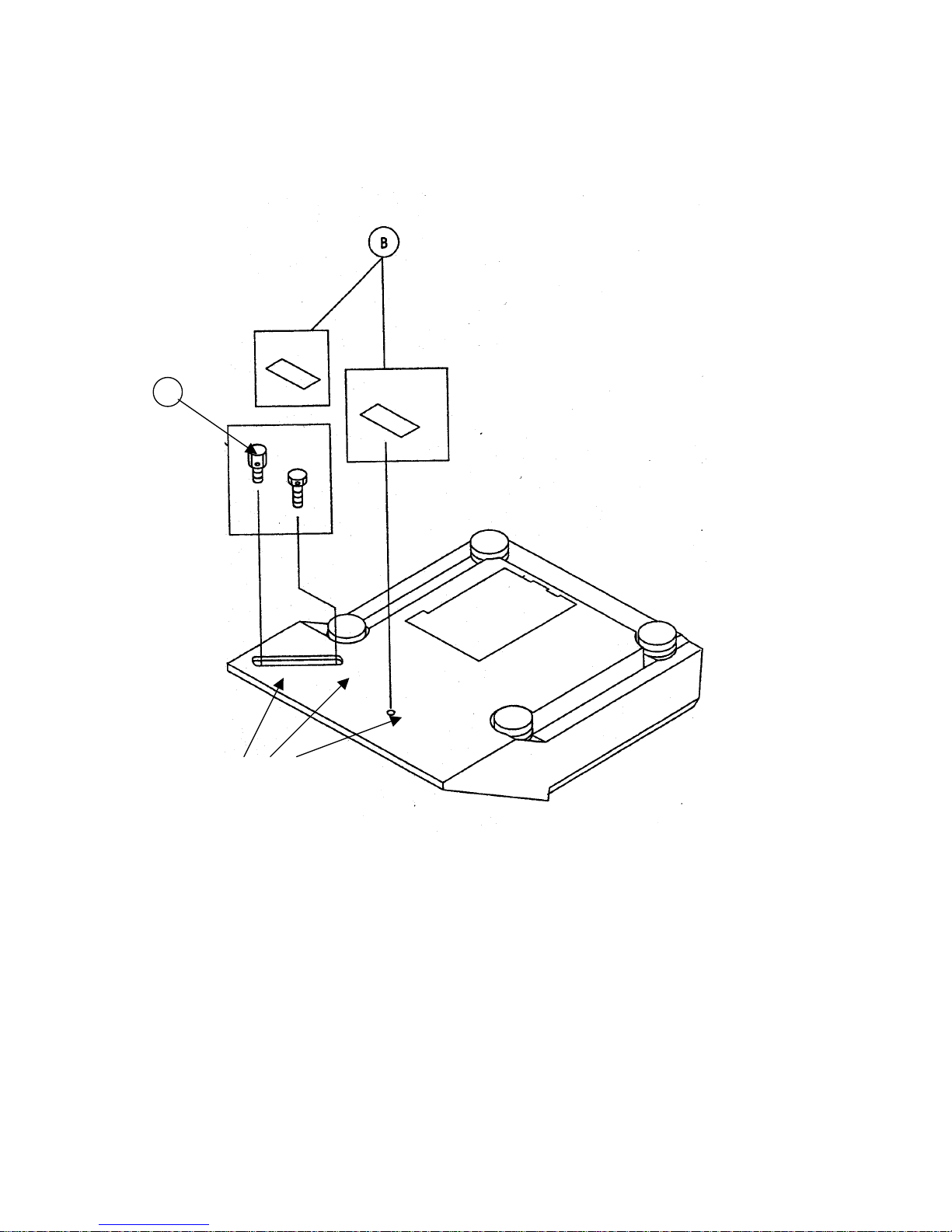
10 Safety seal for calibration
A
Safety seals
(self-sticking seal (B) or
lead (A))
VC-BA-defsin-0212
37
 Loading...