

Page 1

KERN & Sohn GmbH
Ziegelei 1
D-72336 Balingen
E-Mail: info@kern-sohn.com
Tel: +49-[0]7433-9933-0
Fax: +49-[0]7433-9933-149
Internet: www.kern-sohn.com
GB
Service Manual
Electronic Precision Balances
Page 2
KERN 440…N
KERN 440…A
Version 4.0 4/2008
440…N-SH-e-0840
Page 2

GB
KERN 440…N / 440…A
Version 4.0 4/2008
Service Manual
Electronic Precision Balances
2 440…N-SH-e-0840
Table of Contents
1 Features.......................................................................................................................3
2 Calibration Procedure (CAL) .....................................................................................3
3 Internal Calibration Procedure (Linearity Adjustment) ...........................................4
3.1 Readout of the Internal Counts.............................................................................................4
4 Display Segment Test .............................................................................................. 5
5 Functional Block Diagram / Description...................................................................5
5.1 Functional Block Diagram.....................................................................................................5
5.2 Function Description.............................................................................................................6
6 Trouble Shooting........................................................................................................7
7 To Replace PCB..........................................................................................................8
8 To Replace Load Cell Assembly................................................................................9
9 Schematics................................................................................................................ 10
10 Components Layout .................................................................................................12
Page 3

440…N-SH-e-0840 3
1 Features
• Full Tare
• Memory function with indicator
• Stable indicator
• Negative value indication
• Two types of Digital Auto Calibration
• Solder pads to prevent end-user internal calibration
• RS232 interface, printing function
• Custom scale by going through SET manual
- Multiple serial interface modes
- Different communication baud rates selectable
- Auto off enable / disable
- Zero tracking enable / disable
- Multiple calibration weight selectable
- Backlight selectable
- Animal weighing
• Low battery indicator
• Auto off function (battery mode only)
• AC adaptable
• Display segment test function
• Overload protection
• Optional rechargeable battery
• Pre-Tare function
2 Calibration Procedure (CAL)
1. Turn balance on and allow the unit to acclimatize and stabilize for 2 hours.
2. Select the calibration weight according to the operating manual with [Print],
[Mode/Cal] and [Set/M] keys.
3. Press and hold the [Mode/Cal] key until the display shows a flashing weight reading.
The flashing weight reading indicates the correct weight that must be placed on the
weighing pan.
4. Gently place the correct calibration weight on the center on the weighing pan. With the
display still flashing, press the [Set/M] key.
5. The display will now show [Cal F] and then return to normal operating mode. The
calibration is complete when the display correctly shows the weight that is placed on
the weighing pan while the display has stabilized.
6. Remove the calibration weight and press the [TARE] key to reset the zero point.
In case [CAL E] is displayed instead of [CAL F], this indicates a calibration
procedure error. Turn the scale off and then on and repeat the procedure.
Page 4
3 Internal Calibration Procedure (Linearity Adjustment)
1. Remove the top housing of the scale.
2. Connect J3 on the main board by soldering the pads together.
3. Place scale on a hard level surface. With weighing pan installed, turn scale on.
Display shall show the internal counts.
4. The internal counts shall fall in the range from 55 000 to 85 000. In case out of this
range, connect J10 left side or right side to increase or reduce the reading.
Connecting or disconnecting pads on J7, J8 or J9 can fine tune the reading.
5. Press [Set/M] key once. Display will show [CAL 0] and then the required calibration
weight. Place the corresponding calibration weight on the center of the weighing plate.
Press [Set/M] again while the weight placed on the weighing pan is stable.
6. Display will now show [CAL 1] and then the next calibration weight. Place the
corresponding calibration weight on the weighing plate. Repeat this step until display
shows [CAL F]. Remove all weights from weighing pan.
7. Turn the scale off and disconnect J3.
8. Turn scale on and check the accuracy at different weight.
9. Install the top housing of the scale.
In case [CAL E] is display instead of [CAL F], this indicates a calibration procedure error
or wrong weight applied for calibration.
Turn the scale off and then on and repeat the procedure.
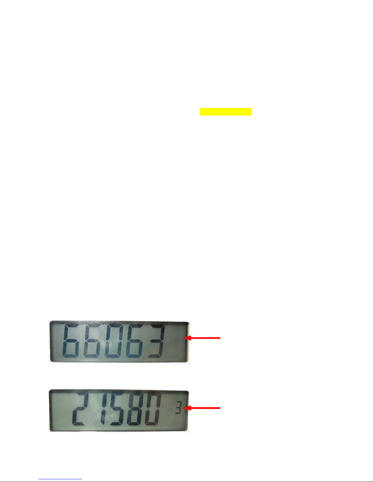
3.1 Readout of the Internal Counts
For example:
Without number
In that case the internal count is 66 063
With number (here 3)
You have to set this number
before the value
In that case the internal count is 321 580
4 440…N-SH-e-0840
Page 5

4 Display Segment Test
Whenever the scale is power on, all segments of the LCD will be turn on for approx.
5 seconds. Check for any missing segment.
5 Functional Block Diagram / Description
5.1 Functional Block Diagram
440…N-SH-e-0840 5
digital signal
analog
signal
Microprocessor
Power control /
Regulator &
Low battery
detector
Keyboard
L C D
A/D Converter
External
Computer /
Printer
RS232 Serial
Interface
Battery
or
Adaptor
Amplifier
Load cell
(Sensor)
Page 6

6 440…N-SH-e-0840
5.2 Function Description
1. Load cell
This is the heart of the whole system. The load cell itself is arranged as a bridge.
The resistance change of the bridge elements is proportional to the load applied on
the load cell. Therefore, the output of the load cell is an analog signal, which is
proportional to the load applied on the scale.
2. Amplifier
The analog signal from the load cell is very small, of the order of micro-volt.
Hence, a linear and stable amplifier is applied to amplify the analog signal to an
appropriate level.
3. A/D Converter
In order for the analog signal can be input to the microprocessor, this part converts the
analog signal to its digital equivalent. The operation of the analog to digital converter
is using a SIGMA DELTA technique and under the control of the microprocessor.
4. Microprocessor
The microprocessor control all the functions of the scale, such as auto zero,
A/D conversion, timings, weight calculation, display, parts counting, RS232 interface,
overload indication, low battery indication, tare, etc….
5. Display
This is the part where the weight is shown out on the LCD display in digital form.
The whole display is driven by the microprocessor.
6. Power Regulator and Low Battery Detector
This part contains the ON/OFF power control. In order for the external power can be
used by other parts of the scale, a regulator is used to regulate the supply.
A low battery detector is employed to make sure that the power supply is strong
enough for normal operation of the scale. If rechargeable battery is installed, it can be
charged up by the charging circuit.
7. Keyboard
The keyboard provides on user interface. [On/Off], [Mode/Cal], [Set/M], [Print] and
[Tare] keys are employed to operate the scale.
8. RS232 Interface
The RS232 serial interface provides the communication to the external computer or
printer.
Page 7

440…N-SH-e-0840 7
6 Trouble Shooting
Power on
↓
Full Segments?
If no display, check battery /adaptor; connection between keyboard—main
board, battery/adaptor—main board.
If missing segments, check fixing of LCD frame, zebra connector under LCD.
↓
Display Zero?
If display [LO], check battery>7.5V, adaptor>9V.
If display [ E] , check internal count.
↓
Proper readout?
If unstable reading, check weighing plate, overload stopper, load cell and wires,
environmental conditions and stable table.
↓
Correct reading?
If not accurate, perform internal calibration.
If cannot reach full capacity, check weighing plate, overload stopper, load cell
and internal zero point.
If always zero, check internal zero point. Internal calibration if necessary.
↓
Proper Data to External Device?
If external device not response, check correct RS232 cable and connection,
application software running correctly, wires connecting D-sub connector and main
PCB.
↓
Normal operation.
Page 8

8 440…N-SH-e-0840
7 To Replace PCB
1. Disassemble top housing of scale.
2. Disconnect PL1, PL2, PL3, JP1 and BZ1 from the PCB. Disassemble the ground wire
screw.
Replace a new PCB. Connect PL1, PL2, PL3, JP1 and BZ1 again.
Assemble the ground wire with screw.
3. Assemble the top housing.
4. Perform internal calibration as described in section 3.
5. Check accuracy of scale at different weight.
440-21N 440-33N 440-35N 440-43N 440-45N
weight
(g)
tol.
(g)
weight
(g)
tol.
(g)
weight
(g)
tol.
(g)
weight
(g)
tol.
(g)
weight
(g)
tol.
(g)
10.000 0.003 50.00 0.02 100.00 0.03 100.0 0.2 200.0 0.2
20.000 0.003 100.00 0.02 200.00 0.03 200.0 0.2 500.0 0.2
30.000 0.003 150.00 0.02 300.00 0.03 300.0 0.2 700.0 0.2
40.000 0.004 200.00 0.02 400.00 0.04 400.0 0.2 1000.0 0.2
440-47N 440-49N 440-51N 440-53N 440-55N
weight
(g)
tol.
(g)
weight
(g)
tol.
(g)
weight
(g)
tol.
(g)
weight
(g)
tol.
(g)
weight
(g)
tol.
(g)
500.0 0.2 1000.0 0.3 1000 2 1000 2 1000.0 0.6
1000.0 0.2 2000.0 0.3 2000 2 2000 2 2000.0 0.6
1500.0 0.2 3000.0 0.3 3000 2 4000 2 4000.0 0.6
2000.0 0.2 4000.0 0.4 4000 2 6000 2 6000.0 0.6
440-35A 440-21A 440-49A
weight
(g)
tol.
(g)
weight
(g)
tol.
(g)
weight
(g)
tol.
(g)
100.00 0.03 10.000 0.003 1000.0 0.3
200.00 0.03 20.000 0.003 2000.0 0.3
400.00 0.04 40.000 0.004 4000.0 0.4
600.00 0.04 60.000 0.004 6000.0 0.4
6. Check other functions, such as Tare, Menory, Print, Mode and Auto-Off.
Page 9

440…N-SH-e-0840 9
8 To Replace Load Cell Assembly
1. Disassemble top housing of scale.
2. Disconnect PL2 from main PCB. Remove the four screws fixing the bottom plate of the
load cell assembly. Replace the load cell with a new one.
Connect PL2 and fix the four screws.
3. Put 110% full capacity loading onto weight stand of scale and adjust the overload
screws.
4. Assemble the top housing.
5. Perform internal calibration as described in section 3.
6. Check accuracy of scale at different weight.
440-21N 440-33N 440-35N 440-43N 440-45N
weight
(g)
tol.
(g)
weight
(g)
tol.
(g)
weight
(g)
tol.
(g)
weight
(g)
tol.
(g)
weight
(g)
tol.
(g)
10.000 0.003 50.00 0.02 100.00 0.03 100.0 0.2 200.0 0.2
20.000 0.003 100.00 0.02 200.00 0.03 200.0 0.2 500.0 0.2
30.000 0.003 150.00 0.02 300.00 0.03 300.0 0.2 700.0 0.2
40.000 0.004 200.00 0.02 400.00 0.04 400.0 0.2 1000.0 0.2
440-47N 440-49N 440-51N 440-53N 440-55N
weight
(g)
tol.
(g)
weight
(g)
tol.
(g)
weight
(g)
tol.
(g)
weight
(g)
tol.
(g)
weight
(g)
tol.
(g)
500.0 0.2 1000.0 0.3 1000 2 1000 2 1000.0 0.6
1000.0 0.2 2000.0 0.3 2000 2 2000 2 2000.0 0.6
1500.0 0.2 3000.0 0.3 3000 2 4000 2 4000.0 0.6
2000.0 0.2 4000.0 0.4 4000 2 6000 2 6000.0 0.6
440-35A 440-21A 440-49A
weight
(g)
tol.
(g)
weight
(g)
tol.
(g)
weight
(g)
tol.
(g)
100.00 0.03 10.000 0.003 1000.0 0.3
200.00 0.03 20.000 0.003 2000.0 0.3
400.00 0.04 40.000 0.004 4000.0 0.4
600.00 0.04 60.000 0.004 6000.0 0.4
7. Check other functions, such as Tare, Memory, Print, Mode and Auto-Off.
Page 10

9 Schematics
10 440…N-SH-e-0840
Page 11

5052-032107
440…N-SH-e-0840 11
Page 12

10 Components Layout
12 440…N-SH-e-0840
 Loading...