

Page 1

KERN & Sohn GmbH
Ziegelei 1
D-72336 Balingen-Frommern
E-Mail: info@kern-sohn.com
Tel: 0049-[0]7433- 9933-0
Fax: 0049-[0]7433-9933-149
Internet: www.kern-sohn.com
GB
Service Manual
Compact Scales
Platform Balances and Terminals
Page 3
KERN FTB/FTC
KERN ITB/ITS/ITT
KERN KMB/KMS/KMT-TM
Version 2.0 03/2007
Page 2

FTx/ITx-SH-e-0720 3
Contents
1 General .......................................................................................................................................... 5
1.1 How to use this service manual? ....................................................................................................... 5
1.2 Service concept ............................................................................................................................... 5
1.3 Introducing the product group ........................................................................................................... 6
1.4 Safety notes..................................................................................................................................... 7
2 Compact scales, small platform FTB/FTC (weighing pan 200x240mm) ............................................. 8
2.1 Scales with strain gauge weighing cells ............................................................................................. 8
2.2 Scales with strain gauge weighing cell and IP65 protection ................................................................. 12
2.3 Display unit FTB ............................................................................................................................... 16
2.4 Display unit FTC ............................................................................................................................... 18
3 Compact scales, large platform FTB/FTC (weighing pan 240x350mm) .............................................. 20
3.1 Scales with strain gauge weighing cell .............................................................................................. 20
3.2 Scales with strain gauge weighing cell and IP65 protection ................................................................. 25
3.3 Display unit FTB ............................................................................................................................... 29
3.4 Display unit FTC ............................................................................................................................... 31
4 Terminals ....................................................................................................................................... 33
4.1 KMB-TM terminal (ITB) ...................................................................................................................... 33
4.2 KMS-TM terminal (ITS) ...................................................................................................................... 35
4.3 KMT-TM terminal (ITT) ....................................................................................................................... 37
4.4 OptionPac ....................................................................................................................................... 39
4.5 Small parts set................................................................................................................................. 41
5 Replacing components with compact scales .................................................................................... 42
5.1 Important notes ............................................................................................................................... 42
5.2 Replacing the keypad overlay ........................................................................................................... 43
5.3 Replacing the AC adapter.................................................................................................................. 43
5.4 Replacing the battery ........................................................................................................................ 43
5.5 Replacing the charging PCB .............................................................................................................. 44
5.6 Replacing the analog PCB ................................................................................................................ 44
5.7 Replacing the display mounting plate, display unit and digital PCB ...................................................... 45
5.8 Replacing the weighing cell .............................................................................................................. 47
Page 3

4 FTx/ITx-SH-e-0720
6 Repair of terminals ......................................................................................................................... 49
6.1 Important information ....................................................................................................................... 49
6.2 Disassembling/reassembling the terminal .......................................................................................... 49
6.3 Replacing the keypad overlay ........................................................................................................... 50
6.4 Replacing the AC adapter.................................................................................................................. 50
6.5 Replacing the analog board.............................................................................................................. 50
6.6 Replacing the display mounting plate, display unit, and digital board .................................................. 51
6.7 Repairing the OptionPac ................................................................................................................... 53
7 Scale definition, settings and diagnostics ...................................................................................... 54
7.1 Accessing and using the technician menu ......................................................................................... 54
7.2 Technician menu – Overview ............................................................................................................ 55
7.3 Admissibility for certification (SCALE –> Metrology) ............................................................................. 56
7.4 Selecting the scale to be configured (SCALE –> Scale 1/Scale 2) ......................................................... 56
7.5 Querying the value of the analog/digital converter (SCALE –> Ramp) ................................................... 56
7.6 Serial number of the scale or terminal (SCALE –> Serial Number) ........................................................ 56
7.7 Entering configuration data (SCALE –> Scale Build) ...........................................................................56
7.8 Setting the GEO adjustment value (SCALE –> Geo Value) .................................................................... 58
7.9 Linearization with simultaneous calibration (SCALE –> LIN-CAL) .......................................................... 58
7.10 Basic calibration (SCALE –> Calibration) ........................................................................................... 59
7.11 Activating control mode (SCALE –> Control Mode) .............................................................................. 59
7.12 Settings for the zero point (SCALE –> Zero) ....................................................................................... 59
7.13 Defining MinWeigh value (SCALE–> Minweigh) .................................................................................. 60
7.14 Settings in the “TERMINAL” menu block .............................................................................................. 60
7.15 Setting of country version ................................................................................................................. 60
8 Additional information .................................................................................................................... 61
8.1 Technical data and tolerances .......................................................................................................... 61
8.2 Notes on load cell capacities ............................................................................................................ 66
8.3 Overview of load cells and preloads .................................................................................................. 67
8.4 Table of geo values.......................................................................................................................... 68
8.5 Interface data .................................................................................................................................. 69
8.6 Attaching weighing platforms ............................................................................................................ 71
9 Software ......................................................................................................................................... 74
9.1 Software architecture ........................................................................................................................ 74
9.2 Error messages after service work ..................................................................................................... 75
9.3 Deleting the scale data in the EAROM ................................................................................................. 75
9.4 Loading new scale software into Flash memory .................................................................................. 76
Page 4

FTx/ITx-SH-e-0720 5
1 General
1.1 How to use this service manual?
This service manual contains instructions for the repair and maintenance work to be performed by service engineers.
It is assumed that the reader is familiar with the operation of the scale and can refer to the relevant operating instructions when
necessary.
1.1.1 Layout of this service manual
This manual comprises nine main sections:
• General: This section which you are looking at now gives instructions on using the service manual, and also provides an
overview of the scales covered by it.
• FTB/FTC (small platform): This section contains the exploded view drawings and spare parts lists for compact scales
with the small platform (weighing pan 200 x 240 mm).
• FTB/FTC (large platform): This section contains the exploded view drawings and spare parts lists for compact scales
with the large platform (weighing pan 240 x 350 mm).
• KMB-/KMS-/KMT-TM: This section contains the exploded view drawings and spare parts lists for terminals.
• Replacing components with compact scales: This section describes all repair work and the replacement of components
for compact scales with large and small platforms. It also contains a list of the tools and working aids required.
• Replacing components with terminals: This section describes all repair work and the replacement of components for
terminals. It also contains a list of the tools and working aids required.
• Scale definition, settings and diagnostics: This section describes how to enter scale setup data, make various settings
and use the diagonstic functions.
• Additional information: This section contains certification tolerances and other technical information plus an overview of all
weighing cells and preloads and a table of geographical adjustment values.
• Software: This section contains information on the various software versions and their compatibility. It also describes
typical error messages that can appear following service work and provides troubleshooting instructions.
1.1.2 Working with the service manual
The exploded view drawings are provided as a guide for disassembly and assembly work and for identifying the order
numbers for spare parts.
When ordering spare parts, please use the information given in the spare parts lists. The item numbers in the first column
"Item" correspond to those on the exploded view drawing opposite.
1.2 Service concept
The scales have been designed so that defective components can be replaced with just a few simple tools. Technician mode
and supervisor mode will already be familiar to you, since this concept has already been used in other KERN & SOHN
products. As almost all parameters can be configured with the keyboard of the scale.
As you can see, we have kept it simple for efficient servicing.
Page 5

6 FTx/ITx-SH-e-0720
1.3 Introducing the product group
The product group comprises the following models, which are all covered by this manual:
FTB, ITB, KMB-TM
The FTB-,ITB-scales and the KMB-terminal possess basic weighing functions for simple weighing duties. They are IP65
versions.
FTC, ITS, KMS-TM
In addition to basic weighing functions, counting scales also have built-in functions for piece counting. An extended keypad
and a display with a visual weighing-in aid are available in order to use these additional functions.
ITT, KMT-TM
In addition to the simple piece counting functions these scales have a numeric keypad as well as totalising, checking and
ID functions.
Common features
Apart from the differences with regard to functions and operating and display elements, all models have the following
common features:
– All models are designed either for direct connection to the AC power line or contain a built-in rechargeable battery.
Rechargeable battery scales are connected to the AC power line via an AC adapter.
– All models are also available as certifiable instruments.
– The weighing cells are strain gauge.
Page 6

FTx/ITx-SH-e-0720 7
1.4 Safety notes
When carrying out service or repair work, always observe the following:
1.5 Environmental protection
Disposal of rechargeable batteries
Please note all current environmental directives when disposing of the terminal. If
the terminal is equipped with a rechargeable battery: The nickel-metal-hydride
(NiMH) storage battery may not be disposed of in the normal refuse. Please
observe local regulations when disposing of environmentally harmful materials.
Disposal of electronic components
Dispose of defective components in strict compliance with all local and national
regulations! In many countries electronic components are classified as hazardous
waste for whose disposal there are special regulations. In some countries
electronic components are collected separately for recycling. If necessary, find out
the applicable regulations from the local authorities!
• Before opening the scale, isolate it from the AC power line (pull out the plug).
• The scales contain precision electronic components that are sensitive to elec-
trostatic discharge. We recommend that you wear a grounding wrist strap
when doing any work in the interior of the scale, in order to prevent any
electrostatic charge building up. Grounding wrist straps are commercially
available from electronic component suppliers.
• Servicing work in explosion hazard zones is strictly prohibited! Ignition
power could inadvertently be generated, causing an explosion. Servicing work
should therefore only be undertaken in secure areas. Please also observe all
special instructions in this service manual relating to work on instruments that
are approved for use in potentially explosive environments. Such instructions
are indicated by the adjacent symbol.
Page 7

8 FTx/ITx-SH-e-0720
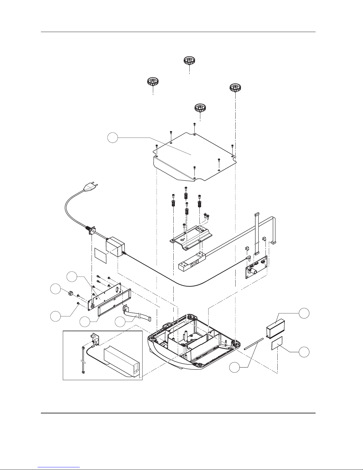
2 Compact scales, small platform
FTB/FTC (weighing pan 200x240mm)
2.1 Scales with strain gauge weighing cells
2
3
4
1
6
7
5
8
Page 8

FTx/ITx-SH-e-0720 9
Item Qty. Description Order No.
1 1 weighing pan 200 x 240 mm 21203071
2 4 rubber cushions
1)
21203073
3 2 countersunk Torx screw M6 x 30 *
4 1 pan support plate 200 x 240 mm –
5 1 housing, with small platform –
6 1 keypad overlay Chap. 2.3 – 2.4
7 1 mounting plate and display unit (digital PCB with LCD and backlighting unit) Chap. 2.3 – 2.4
8 2 EMV clamp 21203480
* included in the small parts set (Chapter 4.5)
1)
New rubber cushions have a hole in the surface to assist with assembly. A pin can be used to insert the cushion into the
corresponding drilled hole in the load plate support
Page 9

10 FTx/ITx-SH-e-0720
Scales with strain gauge weighing cells (continued)
1
2
3
6
5
4
7
8
9
10
16
11
17
15
13
12
18
14
19
19c
19d
19b
19a
Page 10

FTx/ITx-SH-e-0720 11
Item Qty. Description Order No.
1 4 adjustable foot Ø 44 mm (M10 x 0.75 mm) 21203434
2 6 countersunk Torx screw M4 x 12 *
3 1 bottom plate for small platform model –
4 4 button head Torx screw M4 x 12 *
5 4 wide flange washer 4.3 x 20 *
6 4 overload spring **
7 1 overload stop adjustment screw (with certain production series only) **
8 2 countersunk Torx screw M6 x 16 *
9 1 overload plate for small platform model –
10 1 weighing cell with cable (certifiable)
weighing range 3 kg:
LC0765-5-MRV (Standard cell) 21203873
LC0765-5-6TV (Premium cell) 21203877
weighing range 6 kg:
LC0765-10-MRV (Standard cell) 21203874
LC0765-10-6TV (Premium cell) 21203878
11 1 bench AC adapter (always order together with item 16):
EURO version 22011363
USA version 22011364
UK version 22011365
JAPAN version 22011366
Australian version 22011367
external power supply unit (battery charger) for operation with a storage battery
(without power cable) 22011300
socket for external power supply unit 22011311
12 2 spring clip *
13 1 analog PCB BBA AN DMS 7k 21203092
14 1 RS cable 460 mm 21203168
15 1 A/D cable 110 mm, for small platform model 21203164
16 1 adhesive patch for AC adapter or battery (for battery version order 2 pcs.) 21203184
17 1 RS connector plate –
(various types, depending on the equipment)
18 4 raised cheese head Torx screw M4 x 6 *
19 for scales with AccuPac only:
19a 1 accu 14.4V NiMH (always order together with item 16) 22011349
19b 1 battery connection cable –
19c 1 print charger NiMH 22011351
19d 1 battery cable (charging PCB – analog PCB) 21203233
*included in the small parts set (Chapter 4.5) ** see Chapter 5.8 "Replacing the weighing cell"
19d 1
battery cable (charging PCB - analog PCB)
21203233
Page 11

12 FTx/ITx-SH-e-0720
2.2 Scales with strain gauge weighing cell and IP65 protection
1
2
3
4
5
6
7
8
9
Page 12

FTx/ITx-SH-e-0720 13
Item Qty. Description Order No.
1 1 packing for cover plate 21203235
2 1 cover plate –
3 2 countersunk Torx screw M3 x 8 *
4 1 flange D = 100mm –
5 1 diap hragm 21203077
6 1 flange D = 58mm –
7 3 countersunk Torx screw M3 x 10 *
8 4 countersunk Torx screw M3 x 8 *
9 2 EMC clamp 21203480
* included in the small parts set (Chapter 4.5)
Note: Parts of the scale not numbered in the illustration are included in the normal version (Chapter 2.1).
Page 13
14 FTx/ITx-SH-e-0720
Scales with strain gauge weighing cell and IP65 protection (continued)
6
2
1
3
5
4
8
10
9
8
10
9
Page 14
FTx/ITx-SH-e-0720 15
Item Qty. Description Order No.
1 1 bottom plate for small platform model IP65 version 21203511
2 1 RS connector plate IP65 version (various types, depending on the equipment) –
3 1 air supply/extraction filter 21203860
4 1 packing for RS connector plate 21203236
5 6 raised cheese head Torx screw M4 x 6 *
6 1 RS cable 460mm IP65 21203717
8 1 pressure equalizer 21203611
9 1 pressure equalizer tube LA 21203862
10 1 adhesive patch for pressure equalizer 21203184
* included in the small parts set (Chapter 4.5)
Note: Parts of the scale not numbered in the illustration are included in the normal version (Chapter 2.1).
Page 15

16 FTx/ITx-SH-e-0720
2.3 Display unit FTB
1
2
3
4
5
6
Page 16

FTx/ITx-SH-e-0720 17
Item Qty. Description Order No.
1 1 keypad overlay for small platform model 22011400
2 1 display mounting plate (always order together with item 1) 21203120
3 1 LCD 21203134
4 1 backlighting unit 21203136
5 1 digital PCB with FLASH Memory Chip (soldered)
1)
21204025
6 1 Torx oval head tapping screw 2.9 x 13 (red) *
* included in the small parts set (Chapter 4.5)
1)
see Chapter 9.4 for information on loading the software
Page 17

18 FTx/ITx-SH-e-0720
2.4 Display unit FTC
1
2
3
4
5
6
Page 18

FTx/ITx-SH-e-0720 19
Item Qty. Description Order No.
1 1 keypad overlay for small platform model 22011401
2 1 BC display mounting plate (always order together with item 1) 21203120
3 1 LCD 21203687
4 1 backlighting unit 21203137
5 1 Digital PCB with FLASH Memory Chip soldered
1)
21204025
6 1 Torx oval head tapping screw 2.9 x 13 (red) *
* included in the small parts set (Chapter 4.5)
1)
see Chapter 9.4 for information on loading the software
Page 19

20 FTx/ITx-SH-e-0720
2
3
4
1
6
7
5
8
3 Compact scales, large platform
FTB/FTC (weighing pan 240x350mm)
3.1 Scales with strain gauge weighing cell
Page 20

FTx/ITx-SH-e-0720 21
Item Qty. Description Order No.
1 1 weighing pan 240 x 350 mm 21203072
2 4 rubber cushions
1)
21203073
3 2 countersunk Torx screw M6 x 30 *
4 1 pan support plate 240 x 350 mm –
5 1 housing, large platform –
6 1 keypad overlay Chap. 3.3 – 3.4
7 1 mounting plate and display unit (digital PCB with LCD and backlighting unit) Chap. 3.3 – 3.4
8 2 EMC clamp 21203480
* included in the small parts set (Chapter 4.5)
1)
New rubber cushions have a hole in the surface to assist with assembly. A pin can be used to insert the cushion into the
corresponding drilled hole in the load plate support
Page 21

22 FTx/ITx-SH-e-0720
Scales with strain gauge weighing cell (continued)
1
3
2
7
5
4
11
16
17
18
14
19
19c
19d
19b
19a
10
9
8
6
12
15
13
Page 22

FTx/ITx-SH-e-0720 23
Item Qty. Description Order No.
1 4 adjustable foot Ø 55mm (M10 x 0.75 mm) 21203433
2 11 countersunk Torx screw M4 x 10 *
3 1 bottom plate for large platform model –
4 4 button head Torx screw M5 x 12 *
5 4 wide flange washer 5.3 x 20 *
6 4 overload spring **
7 1 overload stop adjustment screw (with specific production series only) **
8 2 countersunk Torx screw M6 x 16 *
9 1 overload plate for large platform model –
10 1 weighing cell with cable (certifiable)
weighing range 15 kg:
LC0785-20-MRV (standard cell) 21203885
LC0785-20-6TV (premium cell) 21203889
weighing range 35 kg:
LC0785-50-MRV (standard cell) 21203886
LC0785-50-6TV (premium cell) 21203890
weighing range 60 kg:
LC0785-100-MRV (standard cell) 21203887
LC0785-100-6TV (premium cell) 21203891
11 1 bench AC adapter (always order together with item 16):
EURO version 22011363
USA version 22011364
UK version 22011365
JAPAN version 22011366
Australian version 22011367
external power supply unit (battery charger) for operation with a storage battery
(without power cable) 22011300
socket for external power supply 22011311
12 2 spring clip *
13 1 analog PCB BBA AN DMS 7k 21203092
14 1 RS cable 460 mm 21203168
15 1 A/D cable 300 mm for large platform model 21203167
16 1 adhesive patch for AC adapter 21203184
2 adhesive patch for battery, thick 21255260
2 adhesive patch for battery, thin 21203184
17 1 RS connector plate (various types, depending on the equipment) –
18 4 raised cheese head Torx screw M4 x 8 *
Page 23

24 FTx/ITx-SH-e-0720
19 for scales with with AccuPac only:
19a 1 accu 14,4V NiMH (always order together with item 16) 22011349
19b 1 battery connection cable –
19c 1 print charger NiMH 22011351
19d 1 battery cable (charging PCB – analog PCB) 21203233
* included in the small parts set (Chapter 4.5)
** see section 5.8 "Replacing the weighing cell"
Page 24

FTx/ITx-SH-e-0720 25
8
1
2
3
4
5
6
7
9
3.2 Scales with strain gauge weighing cell and IP65 protection
Page 25

26 FTx/ITx-SH-e-0720
Item Qty. Description Order No.
1 1 packing for cover plate 21203235
2 1 cover plate –
3 2 countersunk Torx screw M3 x 8 *
4 1 flange D = 100 mm –
5 1 diaphrag m 21203077
6 1 flange D = 58 mm –
7 3 countersunk Torx screw M3 x 10 *
8 4 countersunk Torx screw M3 x 8 *
9 2 EMC clamp 21203480
* included in the small parts set (Chapter 4.5)
Note: Parts of the scale not numbered in the illustration are included in the normal version (Chapter 3.1).
Page 26

FTx/ITx-SH-e-0720 27
Scales with strain gauge weighing cell and IP65 protection (continued)
1
6
2
3
5
4
8
10
9
Page 27

28 FTx/ITx-SH-e-0720
Item Qty. Description Order No.
1 1 bottom plate for large platform model IP65 version 21203512
2 1 RS connector plate IP65 version (various types, depending on the equipment) –
3 1 air supply/extraction filter 21203860
4 1 packing for RS connector plate 21203236
5 6 raised cheese head Torx screw M4 x 8 *
6 1 RS cable 460 mm IP65 21203717
8 1 pressure equalizer 21203611
9 1 pressure equalizer tube LA 21203862
10 1 adhesive patch for pressure equalizer 21203184
* included in the small parts set (Chapter 4.5)
Note: Parts of the scale not numbered in the illustration are included in the normal version (Chapter 3.1).
Page 28

FTx/ITx-SH-e-0720 29
3.3 Display unit FTB
1
2
3
4
5
6
Page 29

30 FTx/ITx-SH-e-0720
Item Qty. Description Order No.
1 1 keypad overlay for large platform model 22011404
2 1 display mounting plate (always order together with item 1) 21203120
3 1 LCD 21203134
4 1 backlighting unit 21203136
5 1 digital PCB with FLASH Memory Chip (soldered)
1)
21204025
6 1 Torx oval head tapping screw 2.9 x 13 (red) *
* included in the small parts set (Chapter 4.5)
1)
see Chapter 9.5 for information on loading the software
Page 30

FTx/ITx-SH-e-0720 31
3.4 Display unit FTC
1
2
3
4
5
6
Page 31

32 FTx/ITx-SH-e-0720
Item Qty. Description Order No.
1 1 keypad overlay for large platform model 22011404
2 1 display mounting plate (always order together with item 1) 21203120
3 1 LCD 21203134
4 1 backlighting unit 21203136
5 1 digital PCB with FLASH Memory Chip (soldered)
1)
21204025
6 1 Torx oval head tapping screw 2.9 x 13 (red) *
* included in the small parts set (Chapter 4.5)
1)
see Chapter 9.5 for information on loading the software
Page 32

FTx/ITx-SH-e-0720 33
4 Terminals
4.1 KMB-TM terminal (ITB)
1
3
22
21
5
4
6
7
8
910
12
14
15
16
17
13
18
19
20
2
23
24
11
Page 33

34 FTx/ITx-SH-e-0720
Item Qty. Description Order No.
1 1 base plate with seal attached 21255118
2 4 rubber foot 00200068
3 8 countersunk screw M4 x 12 Torx T20 *
41 bench AC adapter 8VA (always order together with item 5):
EURO version 22011363
USA version 22011364
UK version 22011365
JAPAN version 22011366
Australian version 22011367
external power supply unit (battery charger) for operation with
a storage battery (without power cable) 22011300
socket for external power supply unit 22011311
5 1 adhesive tape for AC adapter 21203184
6 1 seal for terminal rear panel 21255012
7 1 connector plate for 1 interface (RS232C/load cell) standard –
8 1 countersunk screw M4 x 12 Torx T20 *
9 5 fillister head screw M4 x 8 Torx T20 *
10 1 RS232C interface IP65 with cable (soldered) standard 21203717
11 2 dust cover for interfaces 11101560
12 1 keypad overlay KMB-TM 22011414
13 1 display mounting plate BC (always order together with item 12) 21255041
14 1 LCD 21203134
15 1 backlighting 21203136
16 1 digital PCB with FLASH Memory Chip (soldered) 21204025
17 2 Torx oval head tapping screw 2.9 x 13 (red) *
18 1 analog board 7k 21255054
19 1 fastening clamp for analog board *
20 1 A/D cable 300 mm 21203167
21 1 EMC clamp short 21203480
22 1 EMC clamp long 21255047
23 4 screw lock *
24 1 EMC clamp for analog board 22007948
* included in the small parts set (Chapter 4.5)
Page 34

FTx/ITx-SH-e-0720 35
4.2 KMS-TM terminal (ITS)
1
3
22
21
5
4
7
910
12
14
15
16
17
13
18
19
20
8
2
23
24
6
11
Page 35

36 FTx/ITx-SH-e-0720
Item Qty. Description Order No.
1 1 base plate with seal attached 21255118
2 4 rubber foot 00200068
3 8 countersunk screw M4 x 12 Torx T20 *
41 bench AC adapter 8VA (always order together with item 5):
EURO version 22011363
USA version 22011364
UK version 22011365
JAPAN version 22011366
Australian version 22011367
external power supply unit (battery charger) for operation with a storage battery
(without power cable) 22011300
socket for external power supply unit 22011311
5 1 adhesive tape for AC adapter 21203184
6 1 seal for terminal rear panel 21255012
7 1 connector plate for 1 interface (RS232C/load cell) standard –
8 1 countersunk screw M4 x 12 Torx T20 *
9 5 fillister head screw M4 x 8 Torx T20 *
10 1 RS232C interface IP65 with cable (soldered) 21203717
11 2 dust cover for interfaces 11101560
12 1 keypad overlay KMS-TM 22011415
13 1 display mounting plate (always order together with item 12) 22010038
14 1 LCD 21203687
15 1 backlighting 21203137
16 1 digital board with FLASH Memory Chip (soldered) 21204025
17 2 Torx oval head tapping screw 2.9 x 13 (red) *
18 1 analog board 7 k 21255054
19 1 fastening clamp for analog board * *
20 1 A/D cable 300 mm 21203167
21 1 EMC clamp short 21203480
22 1 EMC clamp long 21255047
23 4 screw lock *
24 1 EMC clamp for analog board 22007948
* included in the small parts set (Chapter 4.5)
Page 36

FTx/ITx-SH-e-0720 37
4.3 KMT-TM terminal (ITT)
1
3
23
22
5
4
12
15
16
17
18
14
19
20
21
13
2
25
7
910
8
24
6
11
Page 37

38 FTx/ITx-SH-e-0720
Item Qty. Description Order No.
1 1 base plate with seal attached 21255118
2 4 rubber foot 00200068
3 8 countersunk screw M4 x 12 Torx T20 *
41 bench AC adapter 8VA (always order together with item 5):
EURO version 22011363
USA version 22011364
UK version 22011365
JAPAN version 22011366
Australian version 22011367
external power supply unit (battery charger) for operation with a storage battery
(without power cable) 22011300
socket for external power supply unit 22011311
5 1 adhesive tape for AC adapter 21203184
6 1 seal for terminal rear panel 21255012
7 1 connector plate for 1 interface (RS232C/load cell) standard –
8 1 countersunk screw M4 x 12 Torx T20 *
9 5 fillister head screw M4 x 8 Torx T20 *
10 1 RS232C interface IP65 with cable (soldered) 21203717
11 2 dust cover for interfaces 11101560
12 1 keypad overlay KMT-TM 22011416
13 1 numeric membrane keypad (always order together with item 12) 21203439
14 1 display mounting plate (always order together with items 12 and 13) 22010039
15 1 LCD 21203687
16 1 backlighting 21203137
17 1 digital board with FLASH Memory Chip (soldered) 22013719
18 2 Torx oval head tapping screw 2.9 x 13 (red) *
19 1 analog board 7k 21255054
20 1 fastening clamp for analog board *
21 1 A/D cable 300 mm 21203167
22 1 EMC clamp short 21203480
23 1 EMC clamp long 21255047
24 4 screw lock *
25 1 EMC clamp for analog board 22007948
* included in the small parts set (Chapter 4.5)
Page 38

FTx/ITx-SH-e-0720 39
1
3
7
8
9
10
12
13
18
17
16
15
4
5
14
6
11
2
4.4 OptionPac
Page 39

40 FTx/ITx-SH-e-0720
Item Qty. Description Order No.
1 1 base plate with seal attached 21255118
2 4 rubber foot 00200068
3 8 countersunk screw M4 x 12 Torx T20 *
4 4 fillister head screw M5 x 12 *
5 1 PCB for NiMH storage battery charger circuit 22011451
6 2 fastening clamp for charging circuit board *
7 1 connecting cable charging circuit – analog board 21203233
8 1 battery cable –
9 1 battery 14.4V NiMH (always order together with item 10) 22011350
10 2 adhesive tape for battery 21255260
11 1 bench AC adapter 8VA (always order together with adhesive tape order no. 21203184):
EURO version 22011363
USA version 22011364
UK version 22011365
JAPAN version 22011366
Australian version 22011367
external power supply unit (battery charger) for operation with a storage battery
(without power cable) 22011300
socket for external power supply unit 22011311
12 1 seal for back panel OptionPac 21255013
13 1 back panel without openings 21255003
14 1 analog interface option board only KMS/KMT-TM 21203383
15 4 tapping screw M3 x 6 –
16 1 EPROM with interface software for analog option (KMS/KMT-TM only) 22013444
17 1 cable for analog option (KMS/KMT-TM only) 21203604
18 1 seal (between OptionPac and terminal) 21255011
5 fillister head screw M4 x 8 Torx T20 *
1 countersunk screw M4 x 10 Torx T20 *
* included in the small parts set (Chapter 4.5)
Page 40

FTx/ITx-SH-e-0720 41
4.5 Small parts set
The small parts set comprises all the standard components (screws, washers, etc.) required for service work on scales and
terminals.
Qty. Description Order No.
1 small parts set 21203404
20 countersunk Torx screw M3 x 8 –
20 countersunk Torx screw M3 x 10 –
20 countersunk Torx screw M6 x 30 –
50 countersunk Torx screw M4 x 10 –
10 countersunk Torx screw M4 x 12 –
20 button head Torx screw M3 x 6 –
30 button head Torx screw M4 x 12 –
30 button head Torx screw M5 x 12 –
20 wide flange washer 4.3 x 20 –
20 wide flange washer 5.3 x 20 –
20 countersunk Torx screw M6 x 16 –
20 spring clip –
50 raised cheese head Torx screw M4 x 8 –
10 screw lock –
10 Torx oval head tapping screw 2.9 x 13 –
Page 41

42 FTx/ITx-SH-e-0720
5 Replacing components with compact scales
5.1 Important notes
This section describes how to change individual components of the compact scales. When doing this, please refer to the
exploded view drawings and spare parts lists in Chapters 2 and 3. Important: After replacing components, a functional check
of the scale must always be carried out.
5.1.1 Safety and environment
The following instructions must be observed for all repairs:
– Disconnect the scale from the power supply before starting repair work!
– The scale contains electronic components which can be damaged by electro-
static discharges. You must therefore always wear a grounded wriststrap
when performing repair work! Grounded wriststraps can be purchased from
specialist electronics dealers.
– Defective components must be disposed of according to the instructions in
Chapter 1!
• Servicing work in explosion hazard zones is strictly prohibited. Ignition
power could inadvertently be generated, causing an explosion. Servicing work
should therefore only be undertaken in secure areas. The location in which
the scale is installed must be declared by the system operator to be safe for the
duration of the repair work. If no such declaration is available, the scale must be
switched off and disconnected from the power supply and moved to a safe area.
• The scales can also be disconnected and reconnected to the power supply in
potentially explosive environments provided that the power supply has first been
switched off.
5.1.2 Tools and working aids
– Screwdrivers: Torx T10, T20, T25, and T30; Phillips 5 mm; flat type size 4
– Torque wrench up to 10 Nm
– Wrench heads Torx T25, T30, and hex 17 mm
– Open-end wrench, size 20
– Feeler gauge
– Carpet knife (“cutter”)
– Grounded wriststrap (as protection against electrostatic discharges)
– Weights of class M1 or F1
5.1.3 Work instructions
Take great care when inserting and tightening screws into holes tapped directly into the aluminum casting: After inserting the
screw, always turn it first about 1 turn counterclockwise until it engages in the existing thread, and only then screw it tight! Do
not tighten the screw too much, since this may damage the thread in the aluminum casting!
Page 42

FTx/ITx-SH-e-0720 43
5.2 Replacing the keypad overlay
• Lift up the defective keypad overlay (if necessary carefully prying it up with a knife) and gently peel it off the scale.
Caution: take care that the specification label is not damaged when the membrane is removed!
• Carefully clean display mounting plate and window (removing all traces of adhesive).
• Make sure that the specification label is in its correct position (must be visible through the window in the keypad overlay),
then peel off the protective film from the new overlay and carefully affix the latter to the display mounting plate.
• Press the keypad overlay down uniformly.
5.3 Replacing the AC adapter
Note: The AC adapter has a fuse as overcurrent protection. For safety reasons this fuse cannot be replaced, and the AC adapter
must therefore be replaced completely if the fuse blows. This applies only to scales that are connected directly to the AC power
line (without rechargeable battery and external AC adapter).
• Unscrew the adjustable feet and remove them.
• Undo the bottom plate retaining screws, removing them and the plate itself.
• Disconnect the AC adapter cable from the analog PCB.
• Remove the AC adapter (held on by an adhesive patch) from the wall of the housing. If necessary, carefully insert a flat
blade (knife or screwdriver) between adapter and housing and pry them apart. Remove all traces of adhesive from the
housing.
• Undo the screws holding the RS connector plate in place (rear panel of scale) and remove the plate.
• Slide the AC adapter power cord grommet out of the RS connector plate. Remove the AC adapter from the scale.
• Place the new AC adapter in the scale and fix it in place with the adhesive patch.
• Slide the power cord grommet into the slot of the RS connector plate and screw the plate in place.
Note for scales with IP65 protection: Check that the seal of the connector plate is still correctly fastened to the housing. If
it is not, the seal must be replaced as follows: Remove the existing seal from the housing so as to leave no trace. Clean and
degrease the surface to which it was fastened. Carefully affix the new seal to the housing in exactly the right position.
• Plug the AC adapter output cable onto the analog PCB.
• Replace the bottom plate and the adjustable feet.
5.4 Replacing the battery
Note: This procedure is only required for scales that have a built-in battery and an external AC adapter (“AccuPac” version).
• Unscrew the adjustable feet screws and remove them.
• Undo the bottom plate retaining screws, removing them and the plate itself.
• Undo the screws holding the RS connector plate in place (rear panel of scale) and remove the plate.
• Slide the charging PCB out from the guide and remove both plugs on the PCB (connection cable to battery or analog PCB).
• Remove the battery from the wall of the housing (held in place by the adhesive strip). If necessary, carefully insert a flat
blade (knife or screwdriver) between the battery and housing and pry them apart. Remove all traces of adhesive from the
housing.
• Remove the battery from the scale and disconnect the cable to the charging PCB.
• Attach the adhesive patch to the wall of the housing, remove its protective foil, place the battery in the scale and press it
Page 43

44 FTx/ITx-SH-e-0720
against the wall of the housing.
• Attach both plugs with connectors to the charging PCB and slide the PCB back it into the guide.
• Replace the RS connector plate and secure with the screws.
Note for scales with IP65 protection: Check that the seal of the connector plate is still correctly fastened to the housing. If
it is not, the seal must be replaced as follows: Remove the existing seal from the housing so as to leave no trace. Clean and
degrease the surface to which it was fastened. Carefully affix the new seal to the housing in exactly the right position.
• Check the connections of all cables: The cables must lie in the correct slots of the housing, to ensure they are not pinched
by the bottom plate.
• Replace the bottom plate and the adjustable feet.
5.5 Replacing the charging PCB
Note: This procedure is only required for scales with a built-in battery (“AccuPac” version). Before fitting the new charging
PCB, check that the correct AC adapter for “AccuPac” operation is used (see spare parts lists in Chapters 2 and 3). If not,
the AC adapter must also be replaced.
• Undo the screws holding the RS connector plate in place (rear panel of scale) and remove the plate.
• Slide the PCB out from the guide and remove both plugs on the PCB (connection cable to battery or analog PCB).
• Attach both plugs with connectors to the (new) charging PCB and slide it into the guide.
• Replace the RS connector plate and secure with the screws.
Note for scales with IP65 protection: Check that the seal of the connector plate is still correctly fastened to the housing. If
it is not, the seal must be replaced as follows: Remove the existing seal from the housing so as to leave no trace. Clean and
degrease the surface to which it was fastened. Carefully affix the new seal to the housing in exactly the right position.
5.6 Replacing the analog PCB
• Unscrew the adjustable feet and remove them. Undo the bottom plate retaining screws, removing them and the plate itself.
• Disconnect weighing cell cable, connecting cable to the digital PCB and the AC adapter output cable from the analog PCB.
• Pull off the two spring clips from the analog PCB and remove it.
• Fit the new analog PCB and fix it in place with the spring clips.
• Connect the weighing cell cable, the A/D cable from the digital PCB and the AC adapter output cable to the analog PCB.
• Replace the bottom plate and the adjustable feet.
Caution: After replacing the analog PCB all scale data must be entered again in technician mode (Chapter 7), plus all
supervisor mode settings must be re-entered! The scale must first be calibrated and a linearization and recalibration carried out
as required.
Page 44

FTx/ITx-SH-e-0720 45
5.7 Replacing the display mounting plate, display unit and digital PCB
The display mounting plate is located underneath the keypad membrane and is attached to the scale housing by 6 snaps. The
display unit comprises the digital PCB, the liquid crystal display (LCD) and the backlighting unit. It is held in place on the
mounting plate by snaps. The digital PCB is connected to the analog PCB and the RS232C interface by two ribbon cables.
5.7.1 Preliminary word
• Unscrew the adjustable feet and remove them.
• Undo the bottom plate retaining screws, removing them and the plate itself.
• Remove both EMC clamps. Undo the red retaining screw (since September 2005) which fastens the display unit to the
mounting plate. Pull back the front cantilever snaps holding the display unit to release it, raise the front edge of the
display unit and withdraw it from the rear snaps. Disconnect the RS232 cable and the connecting cable to the analog PCB
from the digital PCB. Remove the display unit.
5.7.2 Replacing the display mounting plate
Note: In order to replace the display mounting plate, the keypad overlay must be removed. This cannot then be reused and
must also be replaced.
• Remove keypad overlay (Chapter 5.2).
• Push the 3 cantilever snaps at the front edge of the display mounting plate backwards to release the plate and remove it to
the outside.
• Insert the new display mounting plate into the aperture so that it clicks into place.
• Apply the new self-adhesive keypad overlay (Chapter 5.2).
5.7.3 Replacing the liquid crystal display (LCD) or the backlighting unit
• Place the display unit with the digital PCB downwards on a conductive CMOS film.
• Disconnect the backlighting ribbon cable from the digital PCB.
• Carefully insert a flat blade screwdriver (size 4) between the digital PCB and the backlighting unit immediately adjacent to
the connectors.
• With the screwdriver pry the liquid crystal display and the backlighting unit out of the socket strips. When doing this, lever
the shaft of the screwdriver against the edge of the digital PCB. Never lever the tip of the screwdriver against the surface of
the PCB, as this could damage the latter!
• Remove the upper protective film of the backlighting unit.
• Place the new backlighting unit onto the digital PCB (it snaps into place on the board).
• Remove the upper and lower protective cover of the LCD.
• Carefully place the LCD onto the backlighting unit and ensure that the connector pins are correctly aligned with the socket
strips. When correctly positioned, the ends of the LCD and backlighting unit are flush. Use a flat object such as a ruler to
exert a uniform pressure on the LCD and gently push it home.
• Push the backlighting unit ribbon cable connector onto the digital PCB pins.
Page 45

46 FTx/ITx-SH-e-0720
5.7.4 Replacing the digital PCB
• Remove the LCD and backlighting unit as described in the previous chapter.
• Fit LCD and backlighting unit onto the new digital PCB (Chapter 5.7.3).
After the digital PCB has been replaced, the application software of the scale has to be downloaded into the flash memory of
the digital PCB (refer to Chapter 9 of this service manual). If the software was not loaded successfully via the PC, the complete
digital PCB with the soldered-on flash memory chip has to be replaced.
5.7.5 Final reassembly
• Connect the RS232 cable and the cable from the analog PCB to the digital PCB.
• Engage the display unit or the LCD module under the rear snaps of the display mounting plate and then lower its front edge
until it snaps into place. Fit the red retaining screw(s) (since September 2005).
Caution: The red screw is used for adjusting. It must first be tightened completely and then loosened by half a rotation.
If this is not done, the pushbuttons on the digital PCB are too close to the display insert and can no longer be pressed.
The distance between the pushbuttons of the digital PCB and the display insert can be modified by means of this red
adjusting screw. An additional manual keyboard test must always be carried out. In this context fine adjustment also has
to be carried out with the adjusting screw.
Caution: On FTB the LC display is only held in the connector strip on one side. Because of this, for assembly of the PCB,
the display, and the backlighting must be held together by hand, otherwise the backlighting may come out of the drilled
holes in the PCB and be displaced!
• Install both EMC clamps.
• Replace the bottom plate and adjustable feet.
Page 46

FTx/ITx-SH-e-0720 47
5.8 Replacing the weighing cell
5.8.1 Replacing a strain gauge weighing cell
Disassembly
• Remove the weighing pan.
• Scales without IP65 protection: Undo the pan support plate retaining screws and remove the pan support plate.
• Scales with IP65
protection (see exploded view drawings in Chapters 2 and 3):
• Undo the 4 M3 x 8 screws fastening the membrane to the load plate support.
• Undo the two M6 x 30 retaining screws of the load plate support and carefully lift the load plate support off.
Caution: If the load plate support remains attached to the membrane, the membrane must be released with a thin pin.
(Insert the pin through the drilled holes in the load plate and carefully press the membrane down.)
• Undo the 3 M3 x 10 screws fastening the small flange to the membrane. Remove the small flange, the membrane, and
the large flange.
• Undo the 2 M3 x 8 fastening screws of the cover plate. Carefully lift off the cover plate together with the rubber seal.
• Turn the scale upside down, unscrew the adjustable feet and remove them.
• Undo the bottom plate retaining screws, removing them and the plate itself.
Replacing the load cell
• Remove the weighing cell cable connector from the analog PCB.
• Undo the 4 retaining screws for the overload plate. Remove the screws, washers and springs.
• Remove the overload plate with the weighing cell screwed to it.
• Remove the weighing cell retaining screws.
• Screw the new weighing cell to the overload plate. Caution: Before tightening the screws, verify that the weighing cell is
aligned exactly parallel with the edges of the overload plate! Screw torque: 10 Nm!
• There is an adjustment screw for the overload stop with scales from specific production series. The overload stop must then
first be readjusted after replacing the load cell. If the adjustment screw has been removed, a drop of superglue should be
applied to the thread to keep the screw firmly in place after adjustment. A feeler gauge should be used to adjust the overload
stop. The adjustment screw is to be tightened until there is a gap between the screw and weighing cell according to the table
below. Caution: Turning the screw too tightly can damage the weighing cell!
Scale Color of overload spring Gap between adjustment screw and weighing cell
FTB/FTC 3 kg red 0.45 mm
FTB/FTC 6 kg red 0.45 mm
FTB/FTC 15 kg white 0.25 mm
FTB/FTC 35 kg brown 0.25 mm
FTB/FTC 60 kg black 0.40 mm
• Place the overload plate with the weighing cell screwed to it in the scale. Fit the springs and washers, then tighten the
screws.
• Fit the weighing cell cable connector onto the analog PCB pins.
Page 47

48 FTx/ITx-SH-e-0720
Assembly
• Replace the bottom plate and the adjustable feet.
• Scales without IP65 protection: Turn the scale the right way up, replace the pan support plate and secure it with the
screws. Before finally tightening the screws, make sure that the pan support plate is aligned squarely with the scale
housing. Caution: screw torque 10 Nm!
• Scales with IP65
protection (see exploded view drawings in Chapters 2 and 3 ):
• Mount the rubber seal and the cover plate and insert the 2 M3 x 8 fastening screws (but do not tighten them yet).
• Lay the large flange on the cover plate, then lay the membrane in position and align the 3 fastening holes. Next, lay the
small flange in position and align it exactly. Insert the 3 M3 x 10 screws and tighten them evenly together with the two
M3 x 8 screws of the cover plate.
• Align the large flange exactly on the 4 fastening holes of the membrane.
• Lay the load plate support in position, and then insert the two M6 x 30 fastening screws and slightly tighten them. Before
finally tightening the screws, make sure that the pan support plate is aligned squarely with the scale housing.
Caution: screw torque 10 Nm!
• To be able to screw the large flange and the membrane to the load plate support, the flange and the membrane must be
lifted slightly, because the fastening screws are too short to reach to the threaded holes in the flange. To do this, proceed
as follows:
Carefully insert a fine screwdriver under the side of the large flange and lift the flange slightly together with the membrane.
Insert one of the 4 M3 x 8 fastening screws in the corresponding drilled hole in the load plate support and screw it in only
slightly. Insert the remaining 3 M3 x 8 fastening screws into the membrane and then tighten all 4 screws evenly.
Note: Instead of using a screwdriver to lift the flange and membrane, this can also be done by temporarily inserting two
M3 screws at least 15 mm long into two opposite holes in the load plate support and slightly tightening them. (These
temporary screws are long enough to reach the threaded holes in the flange and to lift the flange together with the
membrane). Insert two of the 4 M3 x 8 fastening screws into the free drilled holes in the load plate support and screw
them in slightly. Undo the two temporary screws and insert the two remaining M3 x 8 screws in their place. Tighten all
4 screws evenly.
• Replace the weighing pan.
• Calibrate the scale in technician mode and linearize it (Chapter 7). If a weighing cell with another capacity has been
installed, the new weighing range (“Range”) and the resolution (“Resol.”) must also be selected.
Note: Scales with strain gauge weighing cells have fixed cornerload stops that do not need to be readjusted.
Page 48

FTx/ITx-SH-e-0720 49
6 Repair of terminals
6.1 Important information
When performing repairs please refer to the exploded view drawings and lists of spare parts in Chapter 4 of this manual.
Important: After replacing components, a functional check of the terminal must always be carried out.
6.1.1 Safety and environment
Whenever repairs are carried out, the following safety precautions must always be taken:
– The terminal must be disconnected from the power supply before repair
work is started!
– The terminal and the OptionPac contain electronic components which can be
damaged by electrostatic discharges. You must therefore always wear a
grounded wriststrap when performing repair work. Grounded wriststraps
can be purchased from specialist electronics dealers.
– Defective components must be disposed of according to the instructions in
Chapter 1!
6.1.2 Tools and working aids
– Torx screwdrivers T10, T20, and T30
– Phillips screwdrivers size 2
– Insulated slotted-head screwdriver (with plastic-covered shaft), size 4
– Grounded wriststrap (to protect against electrostatic discharges)
6.1.3 Work instructions
Take great care when inserting and tightening screws into holes tapped directly into the aluminum casting: After inserting
the screw, always turn it first about 1 turn counterclockwise until it engages in the existing thread, and only then screw it
tight! Do not tighten the screw too much, since this may damage the thread in the aluminum casting!
6.2 Disassembling/reassembling the terminal
• Remove base plate from terminal or OptionPac (8 screws, Torx T20).
• If OptionPac is installed: Disconnect all cable connections between OptionPac and terminal in OptionPac.
Tip: Note where cables are connected. Unfasten OptionPac from terminal (4 Phillips screws) and lift off.
• Reassemble in reverse order.
Page 49

50 FTx/ITx-SH-e-0720
6.3 Replacing the keypad overlay
• Lift the defective keypad overlay by a corner and gently peel it off.
• Carefully remove all traces of adhesive with, for example, a wooden or plastic scraper. Caution: Make sure not to
damage the keypad membrane of KMT-TM terminals!
• Carefully clean the windows of the keypad overlay and the display mounting plate.
• Peel off protective film from new overlay.
• Center the keypad overlay on the display mounting plate and press down uniformly.
6.4 Replacing the AC adapter
Note: The AC adapter has a fuse as overcurrent protection. For safety reasons this fuse cannot be replaced, and the AC
adapter must therefore be completely replaced if the fuse blows or the AC adapter is defective.
• Open terminal, remove OptionPac (if present) (Chapter 6.2).
• Peel output cable of AC adapter off analog board. Battery-operated scales only: The output cable of the AC adapter is
plugged into the charging circuit board of the OptionPac and is usually already removed when the OptionPac is
disassembled (Chapter 6.2).
• Remove
AC adapter from wall of housing (attached by adhesive patch). If necessary, carefully insert a flat blade (knife or
screwdriver) between AC adapter and housing and detach AC adapter. Remove all traces of adhesive from housing.
• Undo the 6 screws holding the RS connector plate in place (rear panel of terminal) and remove the plate. (Caution: cable
connections!).
• Remove power cord grommet of AC adapter from RS connector plate. Remove AC adapter from terminal.
• Attach new adhesive patch to housing wall and peel off protective film.
• Place new AC adapter in terminal and press onto adhesive patch.
• Locate the power cord grommet (with its closed side facing up!) in the center of the blanking plate slot, then press the
grommet down thoroughly. This requires a fair amount of force which is intended as it ensures proper IP protection.
Caution: Never use a hammer or similar tool for pushing the grommet into place because this may damage the
wires! Once the grommet is properly located in the slot you may fasten the blanking plate.
• Plug AC adapter output cable onto analog board. Battery-operated terminals: The output cable of the AC adapter must
be plugged onto the charging circuit board in the OptionPac.
• Install terminal/OptionPac (Chapter 6.2).
6.5 Replacing the analog board
• Open terminal, remove OptionPac (if present) (Chapter 6.2).
• Disconnect the load cell connection cable and all other cable connectors from analog board. Tip: Make a note of the
cable connections!
• Pull off the spring clip and the EMC clamp from the analog board and remove it.
• Fit new analog board and fasten in place with the spring clip and the EMC clamp.
• Plug the load cell connection cable and all other cable connectors onto the analog board.
• Close terminal, mount OptionPac (if present) (Chapter 6.2).
Caution: After replacing the analog board all scale data and user settings must be reentered, because they are saved
in the EAROM on the analog board! When they have been reentered, the weighing system must be calibrated/
linearized. These operations are described in Chapter 7 of the this service manual.
Page 50

FTx/ITx-SH-e-0720 51
6.6 Replacing the display mounting plate, display unit, and digital board
The display mounting plate is located underneath the keypad overlay and is attached to the scale housing by 6 snaps. The
display unit comprises the digital PCB, the liquid crystal display (LCD) and the backlighting unit. It is held in place on the
mounting plate and the housing by snaps and screws. The digital PCB is connected to the analog PCB and the RS232C
interface by two ribbon cables (on KMT-TM terminals there is an additional cable for the keypad).
6.6.1 Preliminary work
• Open terminal, remove OptionPac (if present) (Chapter 6.2).
• Undo the two screws (Torx T10) fastening the digital board to the display mounting plate.
• Push back the two (small) black snaps at the front of the display mounting plate and slowly raise the digital board until
it is vertical. Carefully pull the digital board vertically upward and out of the rear snaps.
• Disconnect all cables from the digital board, then remove the board. Tip: Make a note of the cable connections.
KMT-TM only: The membrane cable for the keypad of the KMT-TM (numeric keypad) must also be disconnected from the
digital board. Use a soft felt pen to mark first the membrane cable and then the plug, so you know afterwards how the
cable has to be plugged in. Then slightly pull out the two small black snaps on the left and right of the plug. This releases
the spring mechanism of the plug, and the cable can be pulled off.
6.6.2 Replacing the display mounting plate
Note: In order to replace the display mounting plate, the keypad overlay must be removed. This cannot be reused, and must
therefore also be replaced. On KMT-TM terminals the membrane keypad, which is fastened to the display mounting plate,
must also be replaced.
• Remove keypad overlay (Chapter 6.3).
• Push the 3 cantilever snaps at the front edge of the display mounting plate backwards to release the plate and remove it
to the outside.
• Insert the new display mounting plate into the aperture so that it clicks into place.
• KMT-TM only: Peel the protective film off the new membrane keypad and carefully apply the membrane keypad to the
display mounting plate. Pass the membrane cable through the aperture and into the inside of the terminal.
• Apply the new self-adhesive keypad overlay (Chapter 6.3).
6.6.3 Replacing the liquid crystal display (LCD) and/or the backlighting unit
• Place the display unit with the digital board downwards on a conductive CMOS film.
• Unplug the backlighting ribbon cable from the digital board.
• Carefully insert a flat-bladed screwdriver (size 4) between the digital board and the backlight unit immediately adjacent
to the connectors. Tip: Use an electrician’s screwdriver with an insulated shaft as this reduces the risk of causing
damage.
• Use the screwdriver to pry the liquid crystal display and the backlighting unit out of the socket strip(s). When doing this,
lever the shaft of the screwdriver against the edge of the digital board. Never lever the tip of the screwdriver
against the surface of the digital board, as this could damage the board!
• Peel off the upper protective film of the new backlighting unit.
• Place the new backlighting unit onto the digital board. Two of the four feet of the backlighting unit are in the form of pins.
These pins must be inserted into the corresponding holes in the digital board.
Page 51

52 FTx/ITx-SH-e-0720
• Peel the upper and lower protective films off the new LCD.
• Carefully place the LCD onto the backlighting unit and ensure that the contact pins are correctly aligned with the socket
strip(s). When correctly positioned, the ends of the LCD and the backlighting unit are flush. Use a flat object such as a
ruler to exert a uniform pressure on the LCD and gently push it home.
• Push the backlighting unit ribbon connector onto the digital board pins.
6.6.4 Replacing the digital board
• Remove the LCD and backlighting unit as described in the previous Chapter (6.6.3).
• After the digital board has been replaced, the application software for the terminal must be loaded into the flash memory
of the digital board from the PC (see Chapter 9 of this service manual). If downloading the terminal software via a
computer fails for any reason, the entire digital PCB inlcuding the soldered Flash Memory chip must be replaced.
• Mount the LCD and backlighting unit on the new digital board (Chapter 6.6.3).
Caution: The red screw (since September 2005) is used for adjusting! It must first be tightened completely and then
loosened by half a rotation. If this is not done, the pushbuttons on the digital PCB are too close to the display insert and can
no longer be pressed. The distance between the pushbuttons of the digital PCB and the display insert can be modified by
means of this adjusting screw. An additional manual keyboard test must always be carried out. In this context fine
adjustment also has to be carried out with the adjusting screw.
6.6.5 Final reassembly
• Connect all cables to the digital board (incluning the membrane keypad cable on KMT-TM terminals).
KMT-TM only: The membrane cable for the keypad must also be plugged into the digital board. To do so, pull out the two
small black snaps on the left and right of the plug. Then push the membrane cable into the plug as far as the stop, hold
it in this position and push the two snaps against the plug. The cable is then held fast.
• Engage the display unit under the rear snaps of the display mounting plate and then lower its front edge until it snaps into
place. Fit the retaining screws.
• Install both EMC clamps.
• Install the terminal/OptionPac, if present (Chapter 6.2).
• Replace the bottom plate and secure with 8 screws.
Page 52

FTx/ITx-SH-e-0720 53
6.7 Repairing the OptionPac
6.7.1 Replacing the battery
Note: This section relates only to terminals which have an OptionPac with built-in battery.
• Remove the base plate of the OptionPac (8 screws, Torx T20).
• Remove battery from wall of housing (attached by adhesive patch). If necessary, carefully insert a flat blade (knife or
screwdriver) between battery and housing, then release AC adapter. Remove all traces of adhesive from housing.
• Lift battery out of OptionPac and pull off cable connecting to charging circuit board.
• Fasten adhesive patch to wall of housing, peel off protective film, place battery in OptionPac and press latter against wall
of housing.
• Check all cables are correctly laid. The cables must lie in the correct recesses in the housing so they are not trapped by
the base plate.
• Screw the base plate of the OptionPac on again.
6.7.2 Replacing the charging circuit board
Note: This section relates only to terminals which have an OptionPac with built-in battery. The charging circuit board has an
electronic overload protector which automatically resets after being activated.
• Remove base plate of OptionPac (8 screws, Torx T20).
• Pull off cable from battery (blue plug), then remove the two snap fasteners of the charging circuit board and carefully lift
the board out of the housing.
• Undo all cable connections on charging circuit board.
• Plug cable onto new charging circuit board and place board in housing.
• Fasten board with the two snap fasteners and plug cable into battery (blue plug).
• Screw base plate of OptionPac on again.
6.7.3 Replacing the analog option board
Note: This section relates only to terminals fitted with an OptionPac containing the analog option for connecting a second
weighing platform.
• Remove base plate of OptionPac (8 screws, Torx T20).
• Undo all cable connections on the analog option board. Tip: Make a note of the cable connections.
• Undo the 4 screws fastening the board (Torx T10) and remove the board.
• Using a suitable tool, remove the EPROM from its socket and fit on the new board. Caution: The chamfered corner of the
EPROM must be aligned with the chamfered corner of the socket (see marking)!
• Place new board in housing and fasten with screws.
• Plug in all cables on the analog option board.
• Screw the base plate of the OptionPac on again.
Caution: After the analog option board has been replaced, all the data and user settings for the second weighing
platform must be reentered, because these are stored in the EAROM on the board! The second weighing platform must
then be calibrated and linearized. These steps are described in Chapter 7 of this service manual.
Page 53

54 FTx/ITx-SH-e-0720
7 Scale definition, settings and diagnostics
The menu of the compact scales and the terminals includes a special section dedicated to the service technician. The
technician setup offers settings and procedures for maintenance and diagnostics. Accessing this part of the menu requires
a special password while navigation within the technician menu is the same as with the user and supervsior menu (see User
Manual). Caution: Settings in the technician menu may only be made by qualified personnel. The wrong settings could
result in the scale or terminal not functioning correctly!
7.1 Accessing and using the technician menu
7.1.1 Accessing the technician menu of scales or terminals that are not certified
• Press and hold it down until the prompt to enter the password appears.
• Press . Once you have confirmed the password, the first menu block (“SCALE”) appears. Basically,
the technician menu is the same as the one for the supervisor (see User Manual) except that there are some additional
blocks for setup and diagnostics.
7.1 2 Accessing the technician menu of certified scales or terminals
With certified scales and terminals, direct access to the technician mode (with the and key) is blocked. This is
for technical reasons, and also to comply with regulations. To access the technician mode, proceed as follows:
• Switch off the scale or terminal.
• Remove the bottom plate of the scale by undoing the retaining screws (Torx T20) (see Chapters 4 and 5 for a detailed
description). Important: In order to remove the bottom plate it is necessary to break the certification seal affixed to them!
Once this seal has been destroyed, the scale must be recertified by an accredited organization, and a new
certification seal must be affixed before the instrument may be used as a certified scale again!
• Hold down the service switch (pushbutton) on the analog PCB (indicated by an arrow in the drawings below), while at the
same time switching on the scale or terminal. Keep the service switch pressed in until “SCALE” appears in the display.
small platform model
large platform model
terminals
Page 54

FTx/ITx-SH-e-0720 55
7.2 Technician menu – Overview
The overview below shows the menu blocks holding additional settings dedicated to the technician (“SCALE”, “TERMINAL”).
The settings available to the technician only are printed in boldface. The further menu blocks (“APPLICATION”,
“COMMUNICATION” and “DIAGNOSTICS”) are similar to the ones in the supervisor setup (see User Manual) and are not shown
below. The factory settings are marked with an asterisk (*). Depending on the model some menu items are not available.
Level 1 Level 2 Level 3 Level 4
SCALE Metrolo no Appr
OIML
NTEP
Scale 1/Scale 2 [choose]
Ramp
Serial Number
Scale Build Scale Type Single Range
2Multi Interval
2Multi Range
3Multi Interval
3Multi Range
Base Unit g, kg, oz, lb, t
Ver. Interval e = d, e = 10d
Scale Cap. 1 [entry]
Resolution 1 1200d ...
Scale Cap. 2 [entry]
Resolution 2 1200d ...
Scale Cap. 3 [entry]
Resolution 3 1200d ...
Geo Value 0 ... 31
LIN-CAL 3 Point [Start]
5 Point [Start]
Calibration [Start]
Control Mode
Display Unit 1 g, kg*, oz, lb, t
Unit 2 g*, kg, t, lb, oz
Resolution 1200d ...
Unt.roll Off*, On
Tare Auto tare Off*, On
Chain tare Off, On*
Auto clear tare Off*, On
Tare key Off, On*
Zero Zero-Capt. –2%+18%*, –2+2%
Set Zero [Start]
Auto zero Off, 0.5d, 1d, 2d, 5d, 10d
Restart Off*, On
Filter Vibration Low, Medium*, High
Process Universal*, Dosing
Stability Fast, Standard*, Precise
Fact Temp Off, 1K, 2K, 5K
MinWeigh Set Value [entry]
On/Off Off*, On
Reset [Start]
TERMINAL Device Language English, US English, German,
French, Italian, Spanish
Power off Off, 1 min., 3 min., 5 min., 15 min., 30 min
Power supply (akku) Off, 1 min., 3 min., 5 min., 15 min., 30 min
Contrast 0 ... 5* ... 10
Weight display small*, large
Date/Time Date format EU, US
Date [entry]
Time [entry]
AM*, PM
Beeper Off*, On
Password Supervisor Password [Enter Code], [Retype Code]
Timeout Mode Not active*, Leasing, Text only
Days 1 ... 999
Text1 [entry]
Text2 [entry]
Reset [Start]
Page 55

56 FTx/ITx-SH-e-0720
Only the settings and procedures for the “SCALE” and “TERMINAL” menus that are available exclusively to service technicians
are described here. The other menu options are described in the User Manual.
7.3 Admissibility for certification (
SCALE –> Metrology
)
The following settings are available:
“no Appr” do not certify scale / no certifiable state
“OIML” do certify to OIML / certified
“NTEP” do certify to NTEP / certified
Caution: If a scale is certified, a number of scale settings are no longer available.
7.4 Selecting the scale to be configured (
SCALE –> Scale 1/Scale 2
)
Here you specify which scale you want to configure. This option is only available for two-scale systems, i.e. when the scale
or terminal has an analog option for connecting a second weighing platform.
The same menu blocks that are described in the sections below are available for both scales in the technician menu.
7.5 Querying the value of the analog/digital converter (
SCALE –> Ramp
)
The percentage deflection of the analog/digital converter (“Ramp”) can be displayed in this menu. This value can be used to
determine whether the load cell is operating correctly. Scales with identical and correctly operating load cells have roughly the
same ramp values. The value is dynamic and changes with the load.
7.6 Serial number of the scale or terminal (
SCALE –> Serial Number
)
In this menu, you can display and change the serial number of the scale or terminal, which consists of seven digits. Note: The
number should only be changed or reentered if necessary (e.g. after a new scale PCB is installed). The serial number is found
on the rating plate of the scale or terminal.
The serial number can be entered with the numerical keypad for KMT-TM and terminals (ITT). Press for compact scales
FTx and KMB/KMS-TM terminals (ITB/ITS). The first digit starts flashing and can now be changed with the and
keys.
Confirm new digit with . The second digit starts flashing and can be changed in the same way. This also applies for all
following digits (seven total). To exit the block, press again after entering the last digit.
7.7 Entering configuration data (
SCALE –> Scale Build
)
This menu includes a number of different submenus for entering configuration data for the weighing system. These submenus
are described in the following sections:
Defining the scale type (“Scale Type”) ––> Chapter 7.7.1
Specifying the base unit (“Base Unit”) ––> Chapter 7.7.2
Choosing the verification interval (“Verification Interval”) ––> Chapter 7.7.3
Specifying the capacity of the weighing system (“Scale Capacity”) ––> Chapter 7.7.4
Choosing the resolution (“Resolution”) ––> Chapter 7.7.5
Page 56

FTx/ITx-SH-e-0720 57
7.7.1 Defining the scale type (
SCALE –> Scale Build –> Scale Type
)
The following scale types are available
“Single Range” Single-range scale.
“2 Multi Interval” Scale with coarse range and 1 movable fine range. Automatic switching between the ranges in
both directions.
“2 Multi Range” Scale with coarse range and 1 fixed fine range. Automatic switching to the coarse range. Return
to fine range after reaching a stable zero (gross = 0).
“3 Multi Interval” Scale with coarse range and 2 movable fine ranges.
“3 Multi Range” Scale with coarse range and 2 fixed fine ranges.
7.7.2 Specifying the base unit (
SCALE –> Scale Build –> Base Unit
)
The base unit can be specified in this menu. The base unit is used for determining the capacity of the weighing system and the
resolution and has nothing to do with the weighing unit used for day-to-day operation (this is specified separately, see User
Manual). The following units are available: gram (g), kilogram (kg), metric ton (t), pound (lb) and ounce (oz).
Note: Only “g”, “kg” and “t” are available on weighing systems that are suitable for certification to OIML. Only “kg” and “lb” are
available on weighing systems that are suitable for certification to NTEP.
7.7.3 Choosing the verification interval (
SCALE –> Scale Build –> Verification Interval
)
This setting is only relevant for certifiable weighing systems (Chapter 7.3). The following verification intervals are available:
“e = d” and “e = 10d”.
Note: If the verification interval is set to “e = 10d”, the last digit of the weighing result is displayed in brackets (known as
calibration brackets). These indicate that the last digit is not taken into account for calibration tolerance. If the verification
interval is set to “e = d”, the weighing result is displayed without brackets.
7.7.4 Specifying the capacity of the weighing system (
SCALE –> Scale Build –> Scale Capacity
)
The capacity of the weighing system must be specified when building a new scale using a terminal. Furthermore, if the
analog PCB is replaced, it is necessary to specify the capacity, because the EEPROM on the PCB is set to a default value at the
factory. On compact scales FTx the capacity is shown on the plate above the display and must be set to this value. It is also
necessary to set the capacity if a load cell of a different capacity is installed. In this case the capacity must be set in
accordance with the load cell used (see specifications in Chapter 8).
Entering the scale capacity (in the previously selected basic unit)
The capacity can be entered with the numerical keypad for KMT-TM terminals (ITT). Press the key for compact scales
FTx and KMB-/KMS-TM terminals (ITB/ITS) . The first digit starts flashing and can now be changed with the and
keys. Confirm new digit with the key. The second digit starts flashing and can be changed in the same way. This also
applies for all following digits (seven total).
If it is a multi-interval scale or multi-range scale (see Chapter 7.7.1), this menu block can be accessed separately for
each weighing range (“Scale CAP. 1” to “Scale CAP. 3”, depending on the number of weighing ranges). The additional
blocks for capacity are displayed after the “Resolution” block. The upper capacity limit must be entered for each weighing
range.
Example for a 30 kg dual-range scale: “SCL.CAP 1” = 15 kg, “SCL.CAP 2” = 30 kg. In this example switching from the fine
range to the coarse range occurs at 15 kg.
Page 57

58 FTx/ITx-SH-e-0720
7.7.5 Choosing the resolution (
SCALE –> Scale Build –> Resolution
)
The resolution must be specified when building a new scale using a terminal.
Furthermore, the resolution has to be specified if the analog PCB is replaced, as its EEPROM is factory-set to a basic value.
With compact scales FTx the resolution is indicated on the plate above the display and must be set to this value. The
resolution also needs to be set if a load cell of a different capacity is fitted. In this case the resolution must be entered
according to the load cell used (see technical data in Chapter 8 of this Service Manual). The available resolutions depend
on the capacity of the weighing system.
If it is a multi-interval scale or multi-range scale (see Chapter 7.7.1), this menu block can be accessed separately for
each weighing range ("RESOL. 1" to "RESOL. 3", depending on the number of weighing ranges). The additional blocks for
resolution are displayed after the corresponding block for entering the capacity ("SCL.CAP 1" bis "SCL.CAP 3").
7.8 Setting the GEO adjustment value (
SCALE –> Geo Value
)
The geo adjustment value is used to adjust the weighing system to local gravity conditions (setting range 0 – 31). The table
of geo adjustment values can be found in Chapter 8. Caution: If the scale is calibrated at the installation site, the geo value
may not be changed afterwards.
The value can be changed with the and keys.
7.9 Linearization with simultaneous calibration (
SCALE –> LIN-CAL
)
In this menu block the weighing system can be linearized and calibrated simultaneously. The calibration is purely
computational to compensate for shifts in the maximum load due to linearization. The loads placed on the pan are checked
(±5%), so a basic calibration must already have been performed (see chapter 7.10).
Procedure
• First place a preload on the pan, then select the type of linearization/calibration required and confirm with :
– 3-point linearization (default = 0%, 50% and 100% of the maximum load).
– 5-point linearization (default = 0%, 25%, 50%, 75% and 100% of the maximum load).
• Start the linearization/calibration. The display begins to flash as the scale automatically determines the zero point.
Determination of the zero point can be interrupted manually with , in which case the existing zero point is used as a
reference. This is particularly useful if larger scales have already been loaded with heavy test weights, which would have to be
removed in order to determine the zero point.
• Once the zero point has been determined, the display prompts you to load a weight (half load for 3-point linearization,
quarter load for 5-point linearization). Change the weight if required with (available values depend on the capacity
of the weighing system).
• Once the weight has been placed on the scale and its value confirmed with , linearization is performed at the first
point. The display then prompts for additional weights (the number depends on the type of linearization chosen), which
again can be changed if necessary. At the last linearization point the scale is also calibrated at the same time.
Linearization/calibration can be cancelled at any time with the key.
• Once linearization has been performed at all points, the display confirms that linearization/calibration has been successfully
completed.
Page 58

FTx/ITx-SH-e-0720 59
7.10 Basic calibration (
SCALE –> Calibration
)
The basic calibration uses the display unit 1 (
SCALE –> Display –> Unit 1
).
Procedure
• Before calibration the geo adjustment value should be checked and corrected if necessary (chapter 7.8). It cannot be
changed again subsequently.
• Start the calibration. You will be prompted to confirm the preload. Place the desired preload on the pan and confirm it. If
there is already a test load on the scale, measurement of the preload can be interrupted manually with
, in which
case the existing zero point is used as a reference. This is useful if larger scales have already been loaded with heavy test
weights, which would have to be removed in order to determine the preload.
• Once the preload has been measured, the display prompts you to place the calibration weight corresponding to the
maximum load on the pan. If you do not want to calibrate with this value (e.g. because not enough weights are available), you can choose a different value (available values depend on the capacity of the weighing system). Note: You are
generally recommended to calibrate the scale at maximum load, especially in the case of certifiable scales.
• Place the desired weight on the pan and confirm its value. Calibration is now performed, after which its successful
completion is briefly confirmed. (Calibration can be cancelled at any time with the
key).
7.11 Activating control mode (
SCALE –> Control Mode
)
In this menu the current weighing result is displayed at high resolution (without the weighing unit). This enables the weighing
system to be checked after calibration and/or linearization, for example.
7.12 Settings for the zero point (
SCALE –> Zero
)
This menu includes a number of submenus with settings for the zero point. These submenus are described in the following
sections:
Specifying the zero capturing range (“Zero-Capture”) ––> Chapter 7.12.1
Shifting the calibration zero point (“Set Zero”) ––> Chapter 7.12.2
This menu block also includes the auto zero block. This menu block is also available to the supervisor so it is not described
here (see User Manual).
7.12.1 Specifying the zero capturing range (
SCALE –> Zero –> Zero-Capt.
)
This menu can be used to specify the range in which the scale is set to zero when it is switched on or when is pressed.
The following settings are available:
“–2%/2%” The zero capturing range is –2% to +2% of the nominal load (certifiability to NTEP)
“–2%/+18%” The zero capturing range is –2% to +18% of the nominal load (certifiability to OIML)
Note: The zero capturing range affects the nominal capacity of the weighing system. If the capacity of a load cell is fully
utilized, the zero capturing range can be reduced to –2% to +2%.
7.12.2 Shifting the calibration zero point (
SCALE –> Zero –> Set Zero
)
The calibration zero point can be moved in this menu. This is necessary if an auxiliary preload is used or if calibration cannot
be performed with the existing preload and it is outside the zero capturing range (in which case the scale would not be able to
start up). The corresponding preload must be in position in order for “Set Zero” to be executed. The zero point for calibration by
the supervisor is moved to this value, as is the reference point for the zero capturing range.
Page 59

60 FTx/ITx-SH-e-0720
Procedure
• Ensure that the preload for which the calibration zero point is to be moved is in place.
• Start the function. You will see a prompt asking you if you really want to move the calibration zero point. The calibration
zero point is moved when you confirm the prompt.
If the display signals an underload or overload when you quit this menu, switch the scale off and then on again.
7.13 Defining MinWeigh value
(SCALE–> Minweigh)
The MinWeigh function is to ensure that the weighing results lie within the defined tolerances corresponding to the
specifications of the quality-assurance system used.
If the value for MinWeigh = 0, the menu for the supervisor is fully hidden.
The value can be entered with the numerical keypad for KMT-TM terminals (ITT). Press the key for compact scales FTx
and KMB-/KMS-TM terminals (ITB/ITS). The first digit starts flashing and can now be changed with the and keys.
Confirm new digit with the key.
7.14 Settings in the “TERMINAL” menu block
Most of the TERMINAL menu block is also available to the supervisor and is therefore not described here (see User Manual).
However, this menu block includes a submenu that is restricted to the service technician and is described below.
7.14.1 Defining a timeout (
TERMINAL –> Timeout
)
In this menu you can limit the period of time for which the scale is used. This is particularly useful for leased scales, since it
prevents the scale for being used for longer than the agreed period. This menu item is only available for KMT-TM terminals
(ITT). The following settings are available:
“Not active” There is no restriction on the period of use of the scale (factory setting).
“Leasing” The duration of use is limited to the number of days entered. Enter the number of days (1 - 999)
during which the scale can be used in the "Days" menu item. The duration of use is valid as of the
next day. If the set duration of use has passed, the scale still starts up, but no longer performs
measurements and instead displays the message that the duration of use has passed.
7.15 Setting of country version
After replacing the analog or digital board of the scale it is absolutely necessary to check the country specific settings and to
adjust them if needed. The country specific settings affect the Technician Password, keyboard map, etc. Technician Password
EU = , US = .
For this procedure please connect the scale to an PC with an appropriated cable (PC – Scale, RS232, 9-pin straight cable
Sub D m/f) and open a terminal program on your PC (e.g. HyperTerminal). Verify that the scale is in “Dialog” Mode and the
settings of both interface of the scale and PC correspond.
Depending on your location you may need to send the SICS command “DSK_US” (for USA and Canada) or “DSK_EU” (for all
other countries) to the scale. The scale will send back “DSK_A”. This means that the command had been executed
successfully. If this is not the case, please re-check the connection between scale and PC as well as the interface settings and
repeat this procedure again. To inquire the current status of the “DSK”, send the SICS command “DSK”. Note that each SICS
command must be terminated with CRLF (carriage return, linefeed).
Page 60

FTx/ITx-SH-e-0720 61
8 Additional information
8.1 Technical data and tolerances
8.1.1 Certifiable and certified compact scales with strain gauge load cells (standard)
The following data apply to all certifiable or certified compact scales with strain gauge load cells.
Scale capacity 3 kg 6 kg 15 kg 35kg 60 kg
Weighing range (1/2) [g] 1500/3000* 3000/6000* 6000/15000* 15000/35000* 30000/60000*
Resolution 2 x 3000e 2 x 3000e 2 x 3000e 2 x 3000e 2 x 3000e
Certification class III III III III III
Readability (weighing range 1/2) [g] 0.5/1 1/2 2 5/10 10/20
Linearity [g] +/–0.05 +/–0.1 +/–0.2 +/–0.5 +/–1
+/–0.15** +/–0.2** +/–0.2** +/–0.5** +/–1**
Repeatability s [g] 0.05 0.1 0.2 0.5 1
0.15** 0.1** 0.2** 0.5** 1**
Calibration weight full loac
1)
[kg] 3 6 15 35 60
Repeatability minimum
1)
[kg] 0.1 0.1 0.2 0.4 0.6
Weight class M1 M1 M1 M1 M1
Corner load test weight [kg] 1 2 5 12 20
Corner load tolerance [g] 1 2 5 10 20
Overload stop fixed, not adjustable fixed, not adjustable fixed, not adjustable fixed, not adjustable fixed, not adjustable
Corner load stop fixed, not adjustable fixed, not adjustable fixed, not adjustable fixed, not adjustable fixed, not adjustable
* with approved scales the overload display may only appear when the load is more then 9d above the maximum load
** for scales with IP65 protection degree (FTB)
Note on linearity
The linearity of certified or certifiable scales must be verified at 0%, 50% and 100% of the full load. Tolerances are given
in the following calibration diagrams.
If there are not enough test weights available to
verify the linearity at 0%, 50% and 100% of the full
load, then the preset values can be changed.
1)
Note on calibration
Certified/certifiable scales should be calibrated under
full load. For the limits of permissible calibration
errors for each weighing range, refer to the diagrams
on the next page and the example below:
Example: Maximum permissible errors for 15 kg
(Weighing range 1: 6 kg / 2 g)
(Weighing range 2: 15 kg / 5 g)
– – – – – Maximum permissible errors for decreas-
ing load in weighing range 2
123456
3
2
1
g
-1
-2
-3
kg
4
5
6
7
8
-4
-5
-6
-7
-8
g
8 8 9 10 11 12 13 14 15
Page 61

62 FTx/ITx-SH-e-0720
10 20 30 40 50 60
30
20
10
g
-10
-20
-30
kg
Weighing range Readability e value Certification diagram
3 kg 1.0 g 1
6 kg 2.0 g 2
15 kg 5.0 g 5
35 kg 10.0 g 10
60 kg 20.0 g 20
123456
3
2
1
g
-1
-2
-3
kg
2.5 5 7.5 10 12.5 15
7.5
5
2.5
g
-2.5
-5
-7.5
kg
51015202530
15
10
5
g
-5
-10
-15
kg
0.5 1 1.5 2 2.5 3
1.5
1
0.5
g
-0.5
-1
-1.5
kg
Page 62

FTx/ITx-SH-e-0720 63
8.1.2 Certifiable and certified compact scales with strain gauge load cells (premium)
The following data apply to all certifiable or certified compact scales with premium strain gauge load cells.
Scale capacity 3kg 6 kg 15kg 35 kg 60kg
Weighing range [g] 3000* 6000* 15000* 35000* 60000*
Resolution 1 x 6000e 1 x 6000e 1 x 7500e 1 x 7000e 1 x 6000e
Certification class III III III III III
Readability [g] 0.5 1 2 5 10
Linearity [g] +/–0.05 +/–0.1 +/–0.2 +/–0.5 +/–1
Repeatability s [g] 0.05 0.1 0.2 0.5 1
Calibration weight full load
1)
[kg] 3 6 15 35 60
Calibration weight minimum
1)
[kg] 0.1 0.1 0.2 0.4 0.6
Weight class M1 M1 M1 M1 M1
Corner load test weight [kg] 1 2 5 12 20
Corner load tolerance [g] 0.5 1 2 5 10
Overload stop fixed, not adjustable fixed, not adjustable fixed, not adjustable fixed, not adjustable fixed, not adjustable
Corner load stop fixed, not adjustable fixed, not adjustable fixed, not adjustable fixed, not adjustable fixed, not adjustable
* with approved scales the overload display may only appear when the load is more then 9d above the maximum load
Note on linearity
The linearity of certified or certifiable scales must be verified at 0%, 50% and 100% of the full load. Tolerances are given
in the following calibration diagrams.
If there are not enough test weights available to verify the linearity at 0%, 50% and 100% of the full load, then the preset
values can be changed.
1)
Note on calibration
Certified/certifiable scales should be calibrated under full load. For the limits of permissible calibration errors for each weighing
range, refer to the diagrams on the next page.
Page 63

64 FTx/ITx-SH-e-0720
Weighing range Readability e value Certification diagram
3 kg 0.5 g 0.5
6 kg 1.0 g 1
15 kg 2.0 g 2
35 kg 5.0 g 5
60 kg 10.0 g 10
0.5 1.0 1.5 2.0 2.5 3.0gkg
0.75
0.50
0.25
-0.25
-0.50
-0.75
1.0 2.0 3.0 4.0 5.0 6.0
1.5
1.0
0.5
g
-0.5
-1.0
-1.5
kg
5
g
kg
7.5
5.0
2.5
-2.5
-5.0
-7.5
g
kg
15
10
5
-5
-10
-15
10 15 20 25 30
10 20 30 40 50 60
2.5
g
kg
3
2
1
-1
-2
-3
5 7.5 10 12.5 15
Page 64

FTx/ITx-SH-e-0720 65
8.1.3 Non-certifiable scales with strain gauge load cells (standard resolution 2x3000d)
The following data apply to all non-certifiable compact scales with standard strain gauge load cells.
Scale capacity 3 kg 6 kg 15 kg 35kg 60 kg
Weighing range (1/2) [g] 1500/3000 3000/6000 6000/15000 15000/35000 30000/60000
Resolution 2 x 3000d 2 x 3000d 2 x 3000d 2 x 3000d 2 x 3000d
Certification class ––– ––– ––– ––– –––
Readability (weighing range 1/2) [g] 0.5/1 1/2 2/5 5/10 10/20
Linearity [g] +/–0.05 +/–0.1 +/–0.2 +/–0.5 +/–1
+/–0.15* +/–0.2* +/–0.2* +/–0.5* +/–1*
Repeatability s [g] 0.05 0.1 0.2 0.5 1
0.15* 0.1* 0.2* 0.5* 1*
Calibration weight full load [kg] 3 6 15 35 60
Calibration weight minimum [kg] 0.1 0.1 0.2 0.4 0.6
Weight class M1 M1 M1 M1 M1
Corner load test weight [kg] 1 2 5 12 20
Corner load tolerance [g] 1 2 5 10 20
Over laod stop fixed, not adjustable fixed, not adjustable fixed, not adjustable fixed, not adjustable fixed, not adjustable
Corner load stop fixed, not adjustable fixed, not adjustable fixed, not adjustable fixed, not adjustable fixed, not adjustable
* for scales with IP65 protection degree (FTB)
Note on calibration
It is recommended that non-certifiable scales are also calibrated under full load. If required, however, these can also be
calibrated at less than full load (minimum approx. 25% of full load). The calibration tolerance given in the table applies to
calibration under full load. It is reduced in proportion to the calibration weight used.
Note on linearity
The linearity of noncertified scales must be verified at 0%, 50% and 100% of the full load. Tolerances are given in the
calibration diagrams in the preceding subsection.
If there are not enough test weights available to verify the linearity at 0%, 50% and 100% of the full load, then the preset
values can be changed.
Page 65

66 FTx/ITx-SH-e-0720
8.2 Notes on load cell capacities
The following diagram is a schematic summary of the distribution of the total capacity of a load cell.
Total capacity of load cell
The total capacity of the load cell is the combined sum of the weighing range, the total preload, the zero setting range and any
extended nominal load (if any).
Total preload
The sum of all fittings and equipment that are acting on the load cell upon calibration (load plate support, load plate, roller
track, etc.).
Zero setting range on power-up
The menu for service technicians offers a choice of two zero setting ranges (–2%/18% or –2%/2%).
Weighing range
The weighing range (“Range”) is specified in the technician mode (Chapter 7). Dual-range scales have two weighing ranges.
Note: If the resolution for certifiable scales is set to “e = 10d” in the technician mode, then the last decimal place of the
weighing result is shown in brackets (parentheses). These indicate that the last decimal position is not considered for the
calibration tolerance. If the resolution is set to “e = d”, then the weighing result is shown without parentheses.
Total
preload
0%
Total capacity of load cell
Zero setting
range on power up
Extended
nominal load
Weighing range ("Range")
100%
Page 66

FTx/ITx-SH-e-0720 67
8.3 Overview of load cells and preloads
8.3.1 Strain gauge load cells
Model Weighin pan Weigh- Replacement Preload Preload Total of load Mechanical Preload reserve Cell
(mm) ing cell no. load plate weighing plate support preload switch-on zero capacity (kg)
range support pan and weighing reserve (18% of
(kg) pa n weighing range)
FTB/FTC 200 x 240 mm 3 kg 21203873 0.280 kg 0.540 kg 0.820 kg 1.180 kg 0.540 kg 5 kg
21203877*
FTB/FTC 200 x 240 mm 6 kg 21203874 0.280 kg 0.540 kg 0.820 kg 3.180 kg 1.080 kg 10 kg
21203878*
FTB/FTC 240 x 350 mm 15 kg 21203885 0.840 kg 0.880 kg 1.720 kg 3.280 kg 2.700 kg 20 kg
21203889*
FTB/FTC 240 x 350 mm 35 kg 21203886 0.840 kg 0.880 kg 1.720 kg 13.280 kg 6.300 kg 50 kg
21203890*
FTB/FTC 240 x 350 mm 60 kg 21203887 0.840 kg 0.880 kg 1.720 kg 38.280 kg 10.800 kg 100 kg
21203891*
* Premium strain gauge load cells
Page 67

68 FTx/ITx-SH-e-0720
8.4 Table of geo values
Elevation above sea level in meters
0 325 650 975 1300 1625 1950 2275 2600 2925 3250
Geographical latitude in 325 650 975 1300 1625 1950 2275 2600 2925 3250 3575
the northern or southern Elevation above sea level in feet
hemisphere in degrees 0 1060 2130 3200 4260 5330 6400 7460 8530 9600 10660
and minutes 1060 2130 3200 4260 5330 6400 7460 8530 9600 10660 11730
0°0'-5°46'54433221100
5° 46' - 9° 52' 5 5 4 4 3 3 2 2 1 1 0
9° 52' - 12° 44' 6 5 5 4 4 3 3 2 2 1 1
12°44' - 15° 6' 6 6 5 5 4 4 3 3 2 2 1
15° 6' - 17° 10' 7 6 6 5 5 4 4 3 3 2 2
17°10' - 19° 2' 7 7 6 6 5 5 4 4 3 3 2
19° 2' - 20° 45' 8 7 7 6 6 5 5 4 4 3 3
20°45' - 22° 22' 8 8 7 7 6 6 5 5 4 4 3
22°22' - 23° 54' 9 8 8 7 7 6 6 5 5 4 4
23°54' - 25° 21' 9 9 8 8 7 7 6 6 5 5 4
25°21'-26°45'109988 776655
26°45' - 28° 6' 10 10 9 9 8 8 7 7 6 6 5
28°6'-29°25'11101099887766
29°25' - 30° 41' 11 11 10 10 9 9 8 8 7 7 6
30°41' - 31° 56' 12 11 11 10 10 9 9 8 8 7 7
31°56' - 33° 9' 12 12 11 11 10 10 9 9 8 8 7
33° 9' - 34° 21' 13 12 12 11 11 10 10 9 9 8 8
34°21' - 35° 31' 13 13 12 12 11 11 10 10 9 9 8
35°31' - 36° 41' 14 13 13 12 12 11 11 10 10 9 9
36°41' - 37° 50' 14 14 13 13 12 12 11 11 10 10 9
37°50' - 38° 58' 15 14 14 13 13 12 12 11 11 10 10
38°58' - 40° 5' 15 15 14 14 13 13 12 12 11 11 10
40° 5' - 41° 12' 16 15 15 14 14 13 13 12 12 11 11
41°12' - 42° 19' 16 16 15 15 14 14 13 13 12 12 11
42°19' - 43° 26' 17 16 16 15 15 14 14 13 13 12 12
43°26' - 44° 32' 17 17 16 16 15 15 14 14 13 13 12
44°32' - 45° 38' 18 17 17 16 16 15 15 14 14 13 13
45°38' - 46° 45' 18 18 17 17 16 16 15 15 14 14 13
46°45' - 47° 51' 19 18 18 17 17 16 16 15 15 14 14
47°51' - 48° 58' 19 19 18 18 17 17 16 16 15 15 14
48°58' - 50° 6' 20 19 19 18 18 17 17 16 16 15 15
50° 6' - 51° 13' 20 20 19 19 18 18 17 17 16 16 15
51°13' - 52° 22' 21 20 20 19 19 18 18 17 17 16 16
52°22' - 53° 31' 21 21 20 20 19 19 18 18 17 17 16
53°31' - 54° 41' 22 21 21 20 20 19 19 18 18 17 17
54°41' - 55° 52' 22 22 21 21 20 20 19 19 18 18 17
55°52' - 57° 4' 23 22 22 21 21 20 20 19 19 18 18
57° 4' - 58° 17' 23 23 22 22 21 21 20 20 19 19 18
58°17' - 59° 32' 24 23 23 22 22 21 21 20 20 19 19
59°32' - 60° 49' 24 24 23 23 22 22 21 21 20 20 19
60°49' - 62° 9' 25 24 24 23 23 22 22 21 21 20 20
62° 9' - 63° 30' 25 25 24 24 23 23 22 22 21 21 20
63°30' - 64° 55' 26 25 25 24 24 23 23 22 22 21 21
64°55' - 66° 24' 26 26 25 25 24 24 23 23 22 22 21
66°24' - 67° 57' 27 26 26 25 25 24 24 23 23 22 22
67°57' - 69° 35' 27 27 26 26 25 25 24 24 23 23 22
69°35' - 71° 21' 28 27 27 26 26 25 25 24 24 23 23
71°21' - 73° 16' 28 28 27 27 26 26 25 25 24 24 23
73°16' - 75° 24' 29 28 28 27 27 26 26 25 25 24 24
75°24' - 77° 52' 29 29 28 28 27 27 26 26 25 25 24
77°52' - 80° 56' 30 29 29 28 28 27 27 26 26 25 25
80°56' - 85° 45' 30 30 29 29 28 28 27 27 26 26 25
85°45' - 90° 00' 31 30 30 29 29 28 28 27 27 26 26
Page 68

FTx/ITx-SH-e-0720 69
8.5 Interface data
FTB/FTC compact scales and KMB-/KMS-/KMT-TM terminals (ITB/ITS/ITT) terminals are fitted as standard with one RS232C
interface (DIN 66020; CCITT V24/V.28). They are optionally available with an additional interface (RS232, Ethernet, Digital
I/O (only KMT-TM, ITT) or analog second scale interface (KMS-/KMT-TM,ITS/ITT and FTC)).
The pins of individual interfaces are assigned as below:
Pin view of connector
RS232C standard interface
Pin COM1 (RS232)
1 VCC (+5V power supply)
2) 4)
2 TxD 1 (transmit data)
3 RxD 1 (receive data)
4
3)
5 GND (signal ground)
6
3)
7
3)
8
3)
9
3)
2)
The VCC load on one interface must not exceed 100 mA
3)
must not be connected
4)
can be deactivated in the scale menu
53214
6789
Page 69

70 FTx/ITx-SH-e-0720
Optional interface: RS232C and Digital I/O
Pin COM1 (RS232) COM2 (Digital I/O)
1
1)
GND
2 TxD 1 (transmit data) OUT 0
6)
3 RxD 1 (receive data) OUT 1
6)
4
3)
OUT 2
6)
5 GND (Signal ground) OUT 3
6)
6
3)
IN 0
5)
7
3)
IN 1
5)
8
3)
IN 2
5)
9 VCC (power supply +5V)
2) 4)
IN 3
5)
1)
unassigned
2)
The VCC load on one interface must not exceed 100 mA
3)
must not be connected
4)
can be deactivated in the scale menu
5)
External 5 ... 30 VDC for control inputs
6)
External 5 ... 30 VDC / max. 100 mA for control outputs
Optional interface: RS232C and analog second scale
Pin COM1 (RS232) Analog second scale
1 VCC (power supply +5V)
2) 4)
+Excitation (+8.2 VDC)
2 TxD 1 (transmit data) +Sense
3 RxD 1 (receive data) shield
4
3)
–Sense
5 GND (Signal ground) –Excitation
6
3) 1)
7
3)
+Signal
8
3)
–Signal
9
3) 1)
Page 70

FTx/ITx-SH-e-0720 71
8.6 Attaching weighing platforms
All analog weighing platforms can be attached to the terminals if they conform to the required specifications (see chapter
8.5). A second weighing platform can be attached to terminals equipped with the optional analog interface (OptionPac).
Compact two-scale systems can therefore be constructed using just one terminal.
8.6.1 Instructions on weighing cells
Cells with or without SENSE lines
In case the weighing platform employs a measuring cell without SENSE lines, the pins "+Ex" (Excitation) and "+Se" (Sense)
must be short-circuited at the connector, as well as pins "–Ex" and "–Se".
Cells without SENSE lines Cells with SENSE lines
(required for certifiable weighing systems)
Attaching weighing platforms with several weighing cells
Up to 4 weighing cells can be connected in parallel to a terminal. These weighing cells can be connected in the usual way
using a junction box.
The sum of the rated capacities of the individual cells corresponds to the total capacity of the weighing system. When entering
the weighing capacities in the menu-driven dialog (chapter 7.7.4), the values should be selected so that the individual cells
are not overloaded!
+Si
+Se
+Ex
–Se
–Si
–Ex
+Si
+Se
+Ex
–Se
–Si
–Ex
Page 71

72 FTx/ITx-SH-e-0720
8.6.3 Attaching the weighing platform to the terminal
Before assembling, the terminal must first be disconnected from the power supply!
Undo the gland nut of the heavy gauge cable gland and
remove this together with the black crimping ferrule and the
two washers.
Undo the rear cover plate of the terminal (6 Torx T20
screws) and fold down carefully (cable connections!).
Mount the nut, crimping ferrule and the washer with the
larger hole on the connecting cable of the weighing
platform. Flange the shield of the cable slightly and place
the second washer over it. Insert the cable through the
heavy gauge cable gland of the terminal.
Remove the green plug from the terminal. The plug
connector is fitted with a latch to simplify plugging in and
out. The diagram opposite shows the position of the
connector in the terminal.
Remove the insulation as shown on the left.
Note: For connecting to the analog option, only 100 mm
of cable insulation should be removed.
15mm
135mm
5mm
8.6.2 Preparing the connecting cable for the weighing platform
Page 72

FTx/ITx-SH-e-0720 73
+Ex +Se +Si -Si -Se -Ex
7-pin connector
Secure the individual strands of the connecting cable on the connector. The pin
assignment is shown in the diagram opposite.
The pins are marked as follows:
Si = Signal, Ex = Excitation, Se = Sense.
Attach the connector to the terminal. Caution: When inserting the connector,
ensure that it is centered exactly in the connector socket. If the connector is
skew, then not all pins are in contact!
Reassemble the rear cover plate of the terminal. Note that the connecting cable of
the weighing platform is not crimped!
Tighten the nut of the heavy gauge cable gland. Ensure that the shield of the cable
is held firmly between the two washers.
8.6.4 Connection of a second weighing platform to the analog option
The analog option, which allows the connection of a second weighing platform, is housed in the OptionPac. The connection
of a second weighing platform to the analog option requires a weighing platform already connected to the terminal.
The analog second weighing platform is connected directly to the OptionPac via a 9-pin Sub-D connector.
Pin Assignment
1 + Excitation (+8,2 VDC)
2 + Sense
3 Shield
4 – Sense
5 – Excitation
6 not assigned
7 + Signal
8 – Signal
9 not assigned
Connection of analog weighing platforms without suitable connector
Connect analog weighing platforms that do not have a suitable connector to the
analog option in accordance with the adjacent connection assignment. Also
observe the connection assignment of the weighing platform.
Important: The analog second weighing platform is configured as a reference scale in the factory setting. “Bulk” (bulk scale)
or “Auxiliary” (auxiliary scale) can furthermore be selected in the interface menu “COMMUNICATION –> Option –> Mode”. The
weighing platform can be deactivated with the "Bypass" setting.
Then calibrate the weighing platform ("SCALE 2").
Page 73

74 FTx/ITx-SH-e-0720
9 Software
9.1 Software architecture
All compact scales and terminals have a Flash memory chip on the digital board, which cannot be replaced. On these scales
the software can be loaded into the Flash memory via a PC (see Chapter 9.4).
The type of software depends on the type of scale. The various software versions are not compatible with one another. An
illegible display can indicate that an incorrect software version is installed. The various models of a particular series have
identical software (e.g. FTB 6kg and FTB 15kg).
On powering up, the scale carries out a display test in which the software version is also briefly displayed, e.g.:
"4-1.1.07" or "14-1.1.10".
The first digit designates the scale type and weighing cell
used:
7-x.x.xx: FTB and KMB-TM (ITB)
6-x.x.xx: FTC and KMS-TM (ITS)
5-x.x.xx: KMT-TM (ITT)
20-x.x.xx: Optional analog interface (can be inquired only
by printing out the menu settings)
The following digits (x.xx) designate the actual software
version (e.g. “1.07”).
The number after the hyphen identifies the scale capacity, see
table. If the scale is not calibrated (Error 6), a space is inserted
instead of a number
No. Capacity Note
03 kg
16 kg
2 15 kg
3 35 kg
4 60 kg
5 150 kg terminals only
6 300 kg terminals only
7 600 kg terminals only
8 1500 kg terminals only
9 3000 kg terminals only
The type data for a scale are stored in a memory chip (EAROM) on the analog PCB (serial number, weighing range,
calibration data, etc. ). If there is a second weighing platform connected via the analog option, its type data is stored on the
EAROM of the analog option board (as well as all further settings in the “Scale 2” menu block). If the analog PCB (or analog
option board) is replaced, these data no longer match the scale and must be re-entered.
Note: After replacing the analog PCB of any scale, all user settings must be re-entered as these are also stored on the analog
PCB.
Page 74

FTx/ITx-SH-e-0720 75
Err 6
9.3 Deleting the scale data in the EAROM
In an emergency (e.g. an “Error 53”) the type data of the scale can be deleted. This data is stored in the EAROM on the
analog board. Before you delete the scale data, print it out. This makes re-entering it aftwards much easier!
The data can be deleted as follows:
• Connect the scale to the interface of a PC using a suitable interface cable.
• Set the interfaces of the scale and the PC to the same parameters (protocol, data bits/parity, baud rate). Set the operating
mode of the scale interface to “DIALOG”.
• Start the communication program on the PC (e.g. “HyperTerminal”).
• Enter the following command to delete the data in the EAROM (_ = space character):
“FLU_DEL_E2”.
• Teminate the command with <CRLF> (Return). Deletion of the data is briefly confirmed in the display with “Flush”, and the
scale then re-starts.
• After re-starting, the scale displays “Error 6” (no calibration data). All the type data for the scale must be re-entered and then
the scale must be calibrated (see Chapter 7 of this service manual). If the data in the EAROM of the analog board has been
deleted, the supervisor mode settings must also be re-entered, since these are also stored in the EAROM.
9.2 Error messages after service work
In addition to the errors described in the operating instructions, the following error messages may also appear after carrying
out service work:
No calibration
This error only occurs after reinitializing the EAROM, i.e. after rectifying Error 53.
Remedy: Recalibrate the scale in technician mode (Chapter 7).
Invalid data in EAROM (checksum error)
This error message indicates defective type data in the EAROM.
Remedy: Completely reset the scale by holding down the key. “Flush”
appears in the display. The scale restarts and then indicates Error 6. Re-enter the
type data (weighing range, serial number, certification status, geographical
adjustment value) in technician mode and save them (Chapter 7). Access
technician mode again and then calibrate and linearize the scale.
Err 53
Page 75

76 FTx/ITx-SH-e-0720
9.4 Loading new scale software into Flash memory
Loading new software into the flash memory chip requires a special program, the so-called FlashLoader for the Microsoft
Windows® operating system.
The FlashLoader is used to load the software from the PC onto the scale. If for any reason this is not possible, the digital PCB
on which the Flash Memory chip is soldered must be replaced (see Section 4/5 of this service manual).
9.4.1 Prerequisites
To be able to transfer the new software to the scale you need the following:
– PC Microsoft Windows® operating system (Version 95, 98, NT 4.0, ME, 2000 or XP)
– Connection cable PC –scale (RS232 cable, 9-pin Sub-D connector m/f)
– FlashLoader application
– File with new scale software
Install both the FlashLoader and the scale software in the same folder on any drive of the Windows PC.
9.4.2 Loading the software onto the scale
Before you can load the software onto the scale, you must connect the scale to the serial interface of the PC with the RS232
cable.
Set the COM1 interface on the scale to the following values:
Operating mode: Dialog
Data transmission rate: 9600 baud
Data bits/parity: 8 data bits/no parity (“8 none”)
Transmission protocol: “No” or “Xon/Xoff”
Start the FlashLoader. The first time it is started it prompts
you to select the interface of the PC to which the scale is
connected.
When you have selected the respective interface, click the
“Proceed” button.
Page 76

FTx/ITx-SH-e-0720 77
You will then be prompted to connect the interface cable to
the serial interface of the scale.
Answer the query on the loss of current data with "Proceed"
to start loading the new software. You can still cancel the
process at this point with "Cancel".
De-energize scale or terminal (disconnect power plug) and
confirm with "Proceed".
The "Start Software Update Procedure..." mesage appears.
After loading, reconnect the scale or terminal to the power
supply.
Exit the FlashLoader when the "The scale is now
programmed" message appears.
 Loading...