

Page 1

KERN & Sohn GmbH
Ziegelei 1
D-72336 Balingen-Frommern
E-Mail: info@kern-sohn.com
Tel: 0049-[0]7433- 9933-0
Fax: 0049-[0]7433-9933-149
Internet: www.kern-sohn.com
GB
Service Manual
Electronic Precision Balances
Page 2
KERN EW · EW-C · EG (N)
Version 2.2 01/2007
- 1 - EW_EW-C_EG_N-SH-e-0722
Page 2

GB
KERN EW · EW-C · EG (N)
Version 2.2
Service Manual
Electronic Precision Balances
1 TOTAL VIEW ..........................................................................................................4
1.1 Total View Of EW Type - 220-12000g........................................................ 4
1.2 Total View Of EG Type - 220-620g, 2200g, 4200g..................................... 4
1.3 Total View Of EW-C Type - 600ct (120g)................................................... 5
1.4 Total View Of EW Type - 120g/0,0002g..................................................... 5
2 ELECTRONIC CONSTRUCTION ...........................................................................6
2.1 Block Diagram.............................................................................................. 6
2.2 Whole Wiring................................................................................................ 7
3 TROUBLESHOOTING............................................................................................8
3.1 Troubleshooting Procedure.......................................................................... 8
3.2 Trouble shooting Table................................................................................. 9
3.3 Primary Checks.......................................................................................... 10
3.4 Checks For Electric/Electronic Parts.......................................................... 11
4 ADJUSTMENTS AND SETTINGS........................................................................12
4.1 Span Calibration (CAL) .............................................................................. 12
4.1.1 EW and EW-C Type............................................................................ 12
4.1.2 EG Type.............................................................................................. 13
4.2 Lock Switch................................................................................................ 14
4.3 Corner Error Adjustment ............................................................................ 15
4.3.1 EW – 120-1200 and EW-C Type......................................................... 15
4.3.2 EW – 2200-12K................................................................................... 16
4.4 Adjustment Sequence For Cases............................................................... 17
4.5 Resetting Address Data (Coefficients) ...................................................... 18
4.6 How To Call Address Mode/How To Re-write Address Data ..................... 19
4.7 Linearity Adjustment................................................................................... 20
4.8 Calibration Of Built-In Weight (Ref Cal)...................................................... 23
5 PARTS REPLACEMENTS....................................................................................25
5.1 How to remove the case............................................................................. 25
5.1.1 EW 220-1200...................................................................................... 25
5.1.2 EW 2200-12K...................................................................................... 26
5.1.3 EW-C .................................................................................................. 27
5.1.4 EW 120-4 NM...................................................................................... 28
- 2 - EW_EW-C_EG_N-SH-e-0722
Page 3

5.2 How To Cover The Case............................................................................ 29
5.2.1 EW 120-1200 and EW-C..................................................................... 29
5.2.2 EW 2200-12K...................................................................................... 29
5.3 Sequence Of Mechanism Unit Replacement.............................................. 30
5.3.1 How To Remove The Weighing Mechanism Unit................................ 31
5.3.2 How To Install Weighing Mechanism.................................................. 33
5.4 Plate Rib Replacement............................................................................... 34
5.4.1 Plate Rib Replacement Procedure...................................................... 35
5.5 Sequence Of Tuning-Fork Sensor Replacement........................................ 36
5.5.1 How to uninstall Tuning-fork assy ....................................................... 36
5.6 Sequence Of The AJDP Circuit Board Replacement ................................. 37
5.6.1 How To Remove AJDP Circuit Board.................................................. 37
5.6.2 How To Install AJDP Circuit Board...................................................... 38
5.7 How To Remove Calibration Weight Unit................................................... 39
5.7.1 EG 220-620......................................................................................... 39
5.7.2 EG 2200-4200..................................................................................... 39
5.8 How To Install Calibration Weight Unit....................................................... 41
6 INSTALLATION OPTIONS...................................................................................42
6.1 Installation Of Battery Option ..................................................................... 42
6.1.1 EW 120-1200 and EW-C..................................................................... 42
6.1.2 EW 2200-12K...................................................................................... 43
7 PARTS LIST..........................................................................................................44
7.1 EW 220-1200 ............................................................................................. 44
7.2 EW 2200-12K............................................................................................. 45
7.3 EW-C / EW 120-4 NM................................................................................ 46
- 3 - EW_EW-C_EG_N-SH-e-0722
Page 4
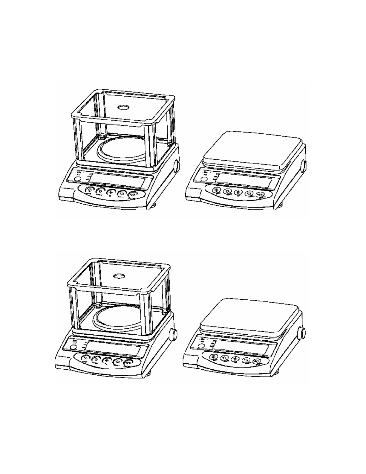
1 Total View
1.1 Total View Of EW Type - 220-12000g
1.2 Total View Of EG Type - 220-620g, 2200g, 4200g
- 4 - EW_EW-C_EG_N-SH-e-0722
Page 5
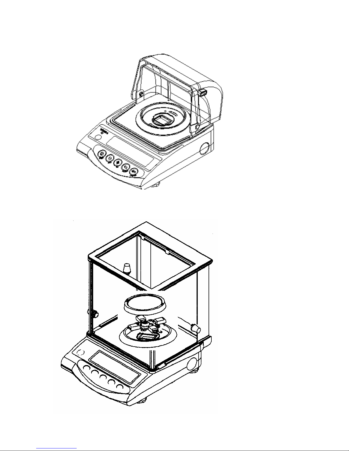
1.3 Total View Of EW-C Type - 600ct (120g)
1.4 Total View Of EW Type - 120g/0,0002g
- 5 - EW_EW-C_EG_N-SH-e-0722
Page 6

2 Electronic Construction
2.1 Block Diagram
EG
EG
AC Adaptor
- 6 - EW_EW-C_EG_N-SH-e-0722
Page 7

2.2 Whole Wiring
EG
EG
- 7 - EW_EW-C_EG_N-SH-e-0722
Page 8

3 Troubleshooting
3.1 Troubleshooting Procedure
- 8 - EW_EW-C_EG_N-SH-e-0722
Page 9
3.2 Trouble shooting Table
Symptoms Causes & Remedy
No display lights on. 1. AJDP board is defective.
2. AC adapter is defective.
3. Wrong connection of connection c ords inside.
4. Built-in battery (option) is discharged.
u-Err
or
o-Err
appears self test of
segments.
1. Wrong weighing pan is applied.
2. Tuning-fork sensor or mechanism unit is defective.
3. AJDP board is defective.
4. Setting of address data has mistake.
5. Coefficient memories (address data) have changed
by noises or static electricity. Adjust linearity.
Display dose not get
settled down.
Display dose not repeat
correctly.
Zero point drifts.
1. Some parts such as stopper touches others.
2. Weighing pan touches other parts.
3. Foreign substance is in the scale.
4. Tuning-fork sensor or mechanism unit is defective.
5. Affected by a wind or disturbing oscillation. Check
environment or working base. Check also setting of
stabilization time. See operation manual.
o-Err
appears
with a net load less than
specified capacity (F.S.
+9d).
1. Gross weight applied to the scale pan (net weight +
tare value) exceeds the scale capacity.
2. Coefficient memories (address data) have changed
by noises or static electricity. Adjust linearity.
3. Setting of address data has mistake.
4. Calibration weight is not correct.
Span is out of specified
range.
1. Tuning-fork sensor or mechanism unit is defective.
2. AJDP board is defective.
3. Setting of address data has mistake.
4. Coefficient memories (address data) have changed
by noises or static electricity.
Linearity is out of
specified range.
1. Tuning-fork sensor or mechanism unit is defective.
2. Setting of address data has mistake.
3. Coefficient memories (address data) have changed
by noises or static electricity.
4. Calibration weight is not correct.
- 9 - EW_EW-C_EG_N-SH-e-0722
Page 10
Symptoms Causes & Remedy
Corner error is too much. 1. Mechanism unit is defective, such as Roberval
plate (Spring) has been bent or twisted.
2. Pan base touches other parts.
Display suddenly
disappeared in operation.
1. Built-in battery (option) has been consumed.
2. AJDP board is defective.
3. AC adaptor is defective.
b-Err
appears.
1. AJDP board is defective.
2. Coefficient memories ( address data) have
changed by noises or static electricity. Adjust
linearity.
d-Err
appears.
1. Address data related to determine the capacity
has been destroyed. Contact the shipper.
2. AJDP board is defective.
I-Err
appears.
1. The calibration weight is less than ½ F.S.
2-Err
appears.
1. The data error exceed s 0.4%. Or perhaps the
scale may be defective. Contact the shipper.
3.3 Primary Checks
1. Is any wind around the site?
Is any oscillation? Is the working table stable.
2. Is anything under the pan base or the weighing pan?
3. Is the weighing pan right one.
4. Is AC adaptor connected both with the scale and with the scale and with the
outlet properly?
5. Is battery option charged sufficiently?
- 10 - EW_EW-C_EG_N-SH-e-0722
Page 11
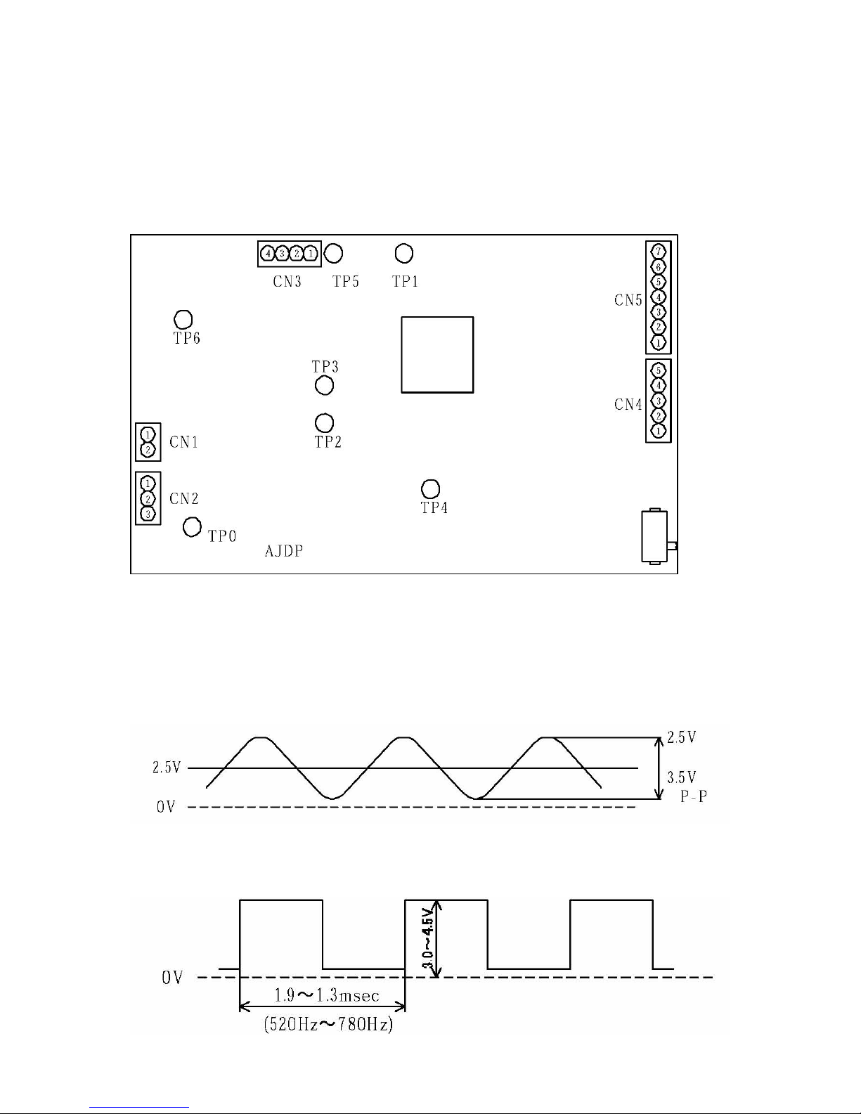
3.4 Checks For Electric/Electronic Parts
-AJDP Circuit board-
Checks for electric/electronic parts are to be carried out on back of AJDP board after
removing the upper case, at test Points and Pins of CN1, CN4, TP4 and TP6.
1. Check of input voltage
TP0 - (1) of CN1 •••••• +8V ~ +12V
2. Power voltage in the circuit
TP0 - (2) of CN4 •••••• +4,75V ~ +5,25V
3. Check of signal wav es (1)
TP0 - TP6
4. Check of signal wav es (2)
TP0 - TP4
- 11 - EW_EW-C_EG_N-SH-e-0722
Page 12

4 Adjustments and Settings
4.1 Span Calibration (CAL)
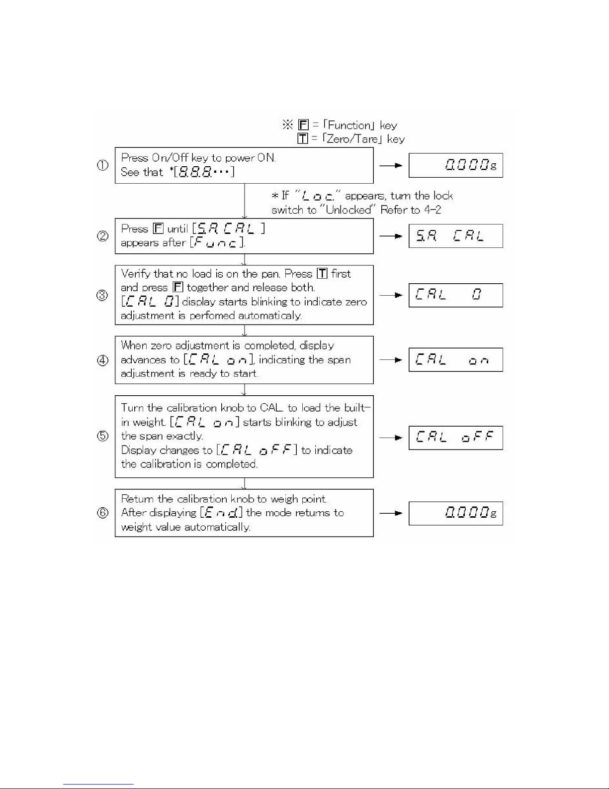
4.1.1 EW and EW-C Type
1. It is recommended to use a calibration weight of better accuracy than the
scale.
2. The calibration is available with ½ of F.S. Nevertheless, it is recommend to
use weight closer to F.S. for accurate calibration.
3. Error messages:
o-Err
: The calibration weight is over the full capacity.
I-Err
: The calibration weight is less than ½ of the capacity.
2-Err
: The data error exceeds 1%. Or perhaps the scale may be defective.
- 12 - EW_EW-C_EG_N-SH-e-0722
Page 13
4.1.2 EG Type
- 13 - EW_EW-C_EG_N-SH-e-0722
Page 14
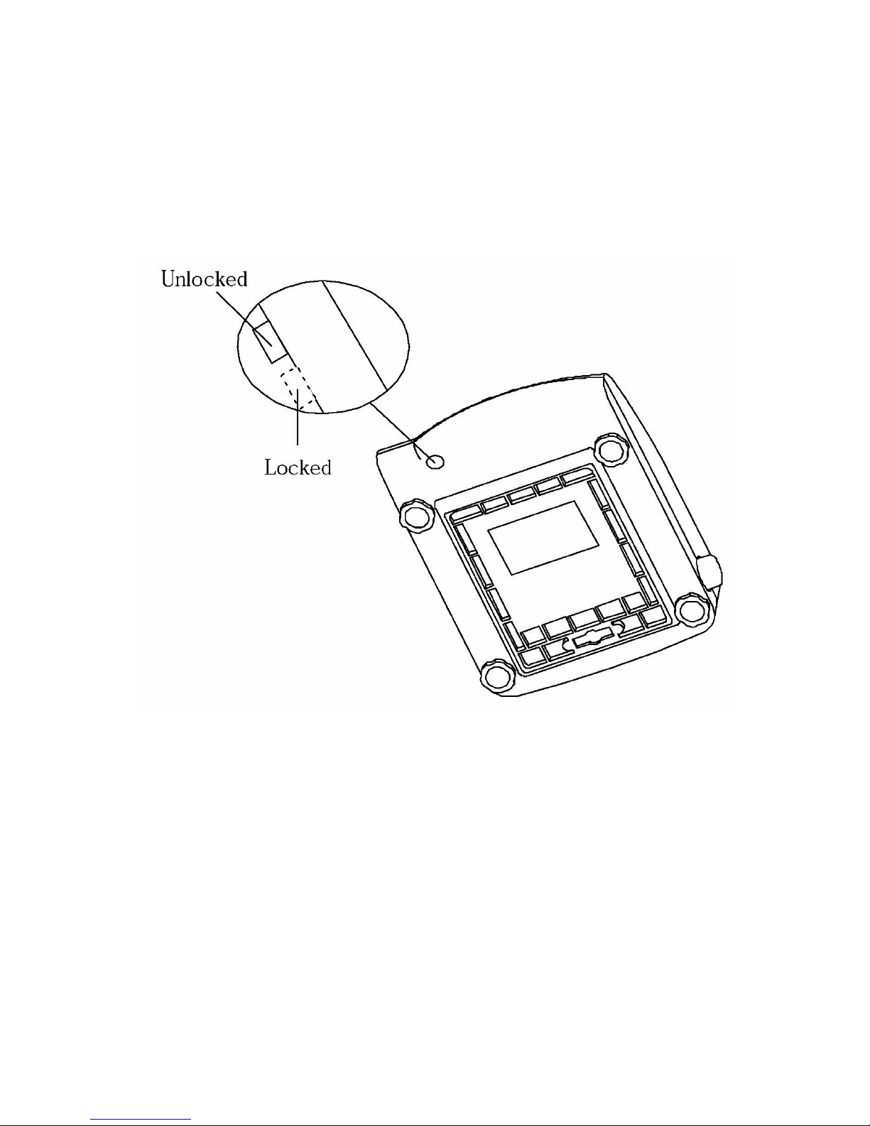
4.2 Lock Switch
Set the lock switch to “Locked” before stamping or sealing so that the user is unable
to change parameters or to calibrate the scale.
- 14 - EW_EW-C_EG_N-SH-e-0722
Page 15

4.3 Corner Error Adjustment
4.3.1 EW – 120-1200 and EW-C Type
Remove the case referring to 5 – 1.
Place the pan base, then place the weighing pan on the mechanism.
Adjust the level.
Remove fixing screw on AJDP board and unplug connector with CN4 on AJDP
board. Adjust corner errors by adjusting bolts referring to following illustrations.
- 15 - EW_EW-C_EG_N-SH-e-0722
Page 16

4.3.2 EW – 2200-12K
- 16 - EW_EW-C_EG_N-SH-e-0722
Page 17

4.4 Adjustment Sequence For Cases
- 17 - EW_EW-C_EG_N-SH-e-0722
Page 18

4.5 Resetting Address Data (Coefficients)
When memories of address data are changed or lost by some reasons, such as by
replacement of PCB, or by noises or static electricity, re-set original data by following
procedure.
1. Location Of Original Data
2. Contents Of Data Sheet
- 18 - EW_EW-C_EG_N-SH-e-0722
Page 19

4.6 How To Call Address Mode/How To Re-write Address Data
EW-C Type
- 19 - EW_EW-C_EG_N-SH-e-0722
Page 20

4.7 Linearity Adjustment
1. How To Adjust Linearity
EW -C Type
EG type
- 20 - EW_EW-C_EG_N-SH-e-0722
Page 21

2. Table Increasing Calibration Weight For Linearity Adjustment
( ) : Cumulative total of weights on the scale
Model
Display
EW 220-3NM
EG 220-3NM
EW 420-3NM
EG 420-3NM
EW 620-3NM
EG 620-3NM
EW 820-3NM
on =
0g
(0g)
0g
(0g)
0g
(0g)
0g
(0g)
on 1
50g
(50g)
100g
(100g)
150g
(150g)
200g
(200g)
on 2
50g
(100g)
100g
(200g)
150g
(300g)
200g
(400g)
on 3
50g
(150g)
100g
(300g)
150g
(450g)
200g
(600g)
on 4
70g
(220g)
120g
(420g)
170g
(620g)
220g
(820g)
Calibration
Weight
Required
50g x 4
20g x1
100g x 4
20g x 1
100g x 4
50g x 4
20g x 1
200g x 4
20g x 1
Model
Display
EW 2200-2NM
EG 2200-2NM
EW 4200-2NM
EG 4200-2NM
EW 6200-2NM EW12000-1NM
on 0
0g
(0g)
0g
(0g)
0g
(0g)
0g
(0g)
on 1
500g
(500g)
1kg
(1000g)
1,5kg
(1500g)
3kg
(3000g)
on 2
500g
(1000g)
1kg
(2000g)
1,5kg
(3000g)
3kg
(6000g)
on 3
500g
(1500g)
1kg
(3000g)
1,5kg
(4500g)
3kg
(9000g)
on 4
700g
(2200g)
1,2kg
(4200g)
1,7kg
(6200g)
3kg
(12000g)
Calibration
Weight
Required
500g x 4
200g x 1
1kg x 4
200g x 1
1kg x 4
500g x 4
200g x 1
2kg x 4
1kg x 4
Please use the weight for F1 (OIML R – 111) or higher class to maintain the
accuracy.
- 21 - EW_EW-C_EG_N-SH-e-0722
Page 22

( ) : Cumulative total of weights on the scale
Model
Display
EW 600-C3 NM EW 120-4 NM
on 0
0g
(0g)
0g
(0g)
on 1
30g
(30g)
30g
(30g)
on 2
30g
(60g)
30g
(60g)
on 3
30g
(90g)
30g
(90g)
on 4
30g
(120g)
30g
(120g)
Calibration
Weight
Required
20g x 4
10g x 4
20g x 4
10g x 4
Please use the weight for E2 (OIML R – 111) or higher class to maintain the
accuracy.
- 22 - EW_EW-C_EG_N-SH-e-0722
Page 23

4.8 Calibration Of Built-In Weight (Ref Cal)
- EG Type -
• Following does not describe the procedure of ordinary span calibration.
• This is the procedure of calibration of the built-in weight with EG scales
• It is necessary to adjust the linearity of the scale beforehand. Refer to 4-7.
- 23 - EW_EW-C_EG_N-SH-e-0722
Page 24

Cautions
(1) [ ] must be carried out in following cases:
(1) When built-in weight is added or replaced.
(2) When linearity adjustment is done.
(3) When AJDP board is replaced.
(2) The quality/tolerance of the reference weight determine the accuracy of the scale.
Use weights of higher accuracy than the scale.
(3) Adjust the level beforehand. The REF CAL must be done in a good environment,
no wind, no oscillation, and no temperature changes.
(4) : The reference weight is less than ½ of F.S.
: The data error exceeds 1%. Adjust the linearity.
- 24 - EW_EW-C_EG_N-SH-e-0722
Page 25

5 Parts Replacements
5.1 How to remove the case
5.1.1 EW 220-1200
(1) Unplug the AC adaptor. Remove the pan and pan base.
(2) Remove case fixing screw with a screwdriver.
(3) Locate two hooks beneath the scale near front. Pull those
two hooks toward you to lift the case up, then shift the case
to rear to release it from hooks.
- 25 - EW_EW-C_EG_N-SH-e-0722
Page 26

5.1.2 EW 2200-12K
(1) Remove the weighing.
(2) Remove case fixing screw with a (+) screwdriver.(2 places in
the top and 1 place in the chassis)
- 26 - EW_EW-C_EG_N-SH-e-0722
Page 27

5.1.3 EW-C
(1) Unplug the AC adaptor. Remove the pan and pan base.
(2) Remove case fixing screw with screwdriver.
(3) Locate two hooks toward you to lift the case up, then shift the
case to rear to release it from hooks.
- 27 - EW_EW-C_EG_N-SH-e-0722
Page 28

5.1.4 EW 120-4 NM
- 28 - EW_EW-C_EG_N-SH-e-0722
Page 29

5.2 How To Cover The Case
5.2.1 EW 120-1200 and EW-C
(1) Cover the scale with the case, seeing cables are just stored inside
properly. Insert the rear hooks first, then press the upper case gently
until two front hooks are set securely.
(2) Drive in case fixing screw securely.
(3) Set pan base and then weighing pan on the scale.
5.2.2 EW 2200-12K
(1) Put the case on properly catching connection codes.
(2) Insert the case fixing screw with a (+) screwdriver. (2 places in top and
1 place in the chassis).
(3) Install the pan base and put the weighing pan on.
- 29 - EW_EW-C_EG_N-SH-e-0722
Page 30

5.3 Sequence Of Mechanism Unit Replacement
- 30 - EW_EW-C_EG_N-SH-e-0722
Page 31

5.3.1 How To Remove The Weighing Mechanism Unit
5.3.1.1 EW 120-1200 and EW-C
(1) Remove the case referring to 5-1.
(2) Remove four sensor cover fixing screw.
(3) Remove wires to the tuning-fork sensor, by welding solders at AJDP
circuit board
(4) Remove the AJDP circuit board fixing screw.
AJDP Circuit Board Fixing Screw
- 31 - EW_EW-C_EG_N-SH-e-0722
Page 32

* For EG series (With-internal-calibration type), refer to section 5-6.
(5) Remove three mechanism unit screws.
(6) Remove the mechanism unit by holding the chassis.
Mechanism unit fixing screws
5.3.1.2 EW 2200-12K
(1) Remove the case referring to 5-1.
(2) Remove wires to the Tuning-fork sensor, by welding solders at AJDP
circuit board.
(3) Remove the AJDP circuit board fixing screw and AJDP circuit board.
AJDP Circuit Board Fixing Screws
- 32 - EW_EW-C_EG_N-SH-e-0722
Page 33

* For EG series (With-internal-calibration type), refer to section 5-6.
(4) Remove four mechanism unit fixing screws
(5) Remove (cut) the board band.
(6) Remove the mechanism unit by holding at the chassis.
5.3.2 How To Install Weighing Mechanism
(1) Place the mechanism on the chassis. Fit it with the fixing screws.
(2) Solder wires of the Tuning-fork sensor to the AJDP circuit board.
(3) (1)Cover the mechanism unite with the sensor cover. Fit it with four
fixing screw. (EW 120-1200).
(2)Fix the Tuning-fork sensor wire to hexagon pillar with cord
band. (EW2200-12K)
(4) Cover the scale referring to 5-2.
Circuit Board Fixing Screw
- 33 - EW_EW-C_EG_N-SH-e-0722
Page 34

5.4 Plate Rib Replacement
- 34 - EW_EW-C_EG_N-SH-e-0722
Page 35

5.4.1 Plate Rib Replacement Procedure
(1) Remove the mechanism unit from the chassis. (5-3)
(2) Replace the tuning-fork sensor.
(3) Attach the fixing jig with fixing screws for the tuning-fork sensor assy.
*The fixing jig should be attacked to the guide link.
(4) Remove the damaged plate rib by unscrewing and fix the new one.
(5) Remove the fixing jig.
(6) Fix the tuning-fork sensor assy. (torque 20kgfcm)
- 35 - EW_EW-C_EG_N-SH-e-0722
Page 36

5.5 Sequence Of Tuning-Fork Sensor Replacement
5.5.1 How to uninstall Tuning-fork assy
(1) Remove the mechanical unit from the chassis.
(2) Replace the tuning-fork sensor.
(3) Insert shim at stopper.
(4) While holding guide link down to under direction, tighten screws.
(Need the torque 25kgfcm)
- 36 - EW_EW-C_EG_N-SH-e-0722
Page 37

5.6 Sequence Of The AJDP Circuit Board Replacement
5.6.1 How To Remove AJDP Circuit Board
(1) Remove the case referring to 5-1.
(2) Remove wires to the Tuning-fork sensor, by welding solders at AJDP
circuit board.
(3) Remove the AJDP circuit board fixing screw.
(4) Unplug connectors at CN1, CN4, (and CN3 with AJH-CE) on AJDP
board. With battery option, unplug CN5, in addition.
Circuit Board Fixing Screw
- 37 - EW_EW-C_EG_N-SH-e-0722
Page 38

5.6.2 How To Install AJDP Circuit Board
(1) Solder wires of the Tuning-fork sensor to the new AJDP board
(2) Plug connectors.
CN1 : AJLF cord
CN3 : Calibration cord
CN4 : AJIF cord
CN5 : Battery cord
(3) Place the AJDP board on the chassis. Fix it with a fixing screw.
(4) Cover the scale referring to 5-2.
- 38 - EW_EW-C_EG_N-SH-e-0722
Page 39

5.7 How To Remove Calibration Weight Unit
5.7.1 EG 220-620
1. Remove the CN3 connector. (Removing AJDP P.C.B. in advance makes it easy to
do it.)
2. Remove (cut) the cord band.
3. Unscrew at two points.
5.7.2 EG 2200-4200
(1) Remove SW cord assy from AJDP circuit board
(2) Remove the weight holder
- 39 - EW_EW-C_EG_N-SH-e-0722
Page 40

Weight Holder
(3) Remove the side ring and disassemble the weight
Weight Fixing Screw Side Ring
(4) Remove the weight shaft from the mechanical main unit
Weight Shaft
- 40 - EW_EW-C_EG_N-SH-e-0722
Page 41

5.8 How To Install Calibration Weight Unit
Follow the instruction in 5-7 by the opposite order.
Refer to the position for the installation below.
- 41 - EW_EW-C_EG_N-SH-e-0722
Page 42

6 Installation Options
6.1 Installation Of Battery Option
6.1.1 EW 120-1200 and EW-C
(1) Remove the case referring to 5-1.
(2) Plug AJ battery cord to CN5 on AJDP board.
(3) Install AJ battery holder assy.
(4) Cover the scale and stick battery label above power jack on the rear panel.
Battery Label
- 42 - EW_EW-C_EG_N-SH-e-0722
Page 43

6.1.2 EW 2200-12K
(1) Remove the case referring to 5-1.
(2) Plug AJ battery cord to CN5 on AJDP board.
(3) Fasten the AJM battery held together into the nylon-clamp which has holed the
cord of the AJMIF circuit board assy.
Nylon Clamp
AJMBT Assy
(4) Cover the scale and stick the battery label above power jack on the rear panel.
Battery Label
- 43 - EW_EW-C_EG_N-SH-e-0722
Page 44

7 Parts List
7.1 EW 220-1200
EW 220/-420/-620
EG 220/-420/-620
EW 820/-1200
EG 220/-420/-620
- 44 - EW_EW-C_EG_N-SH-e-0722
Page 45

7.2 EW 2200-12K
- 45 - EW_EW-C_EG_N-SH-e-0722
Page 46

7.3 EW-C / EW 120-4 NM
EW 600-C3 NM EW 120-4 NM
- 46 - EW_EW-C_EG_N-SH-e-0722
 Loading...