

Page 1
KERN & Sohn GmbH
Ziegelei 1
D-72336 Balingen
E-Mail: info@kern-sohn.com
Tel: +49-[0]7433- 9933-0
Fax: +49-[0]7433-9933-149
Internet: www.kern-sohn.com
Installationsanleitung Stativ
Assembly instructions Tripod
Notice de montage Statif
Instrucciones de montaje Tripode
Istruzioni di montaggio Treppiede
Návod k montáži Stojan
Montage-instructies Statief
Instruções de montagem Tripode
Instrukcja montażu Statyw
Инструкция по монтажу Штатив
KERN DE-A10
Version 1.0
DE-A10-IA-multi-1010
Page 2

D
KERN DE-A10
Version 1.0 04/2010
Installationsanleitung Stativ
Lieferumfang:
Stück Bauteile
1 Stativ
4 Schrauben „Anzeigegerät“
3 Schrauben „Stativfuß“
Montage Stativ:
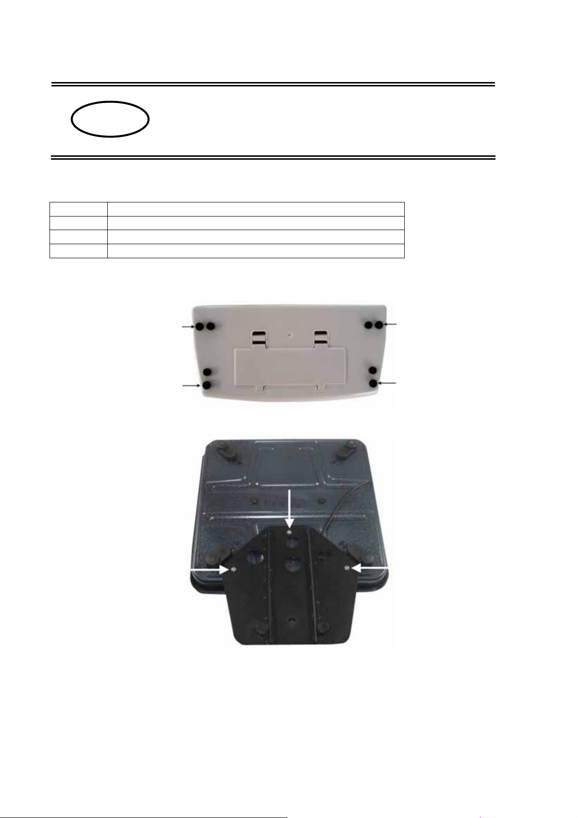
Gummipfropfen entfernen
Abbildungsbeispiel Wägeplatte 315 x 305 x 75 mm
Kabel lösen. Stativfuß lt. Abb. mit den 3 Schrauben und Unterlegscheiben an
Waagenunterseite befestigen. Darauf achten, dass das Kabel nicht eingeklemmt oder
beschädigt wird.
2 DE-A10-IA-multi-1010
Page 3

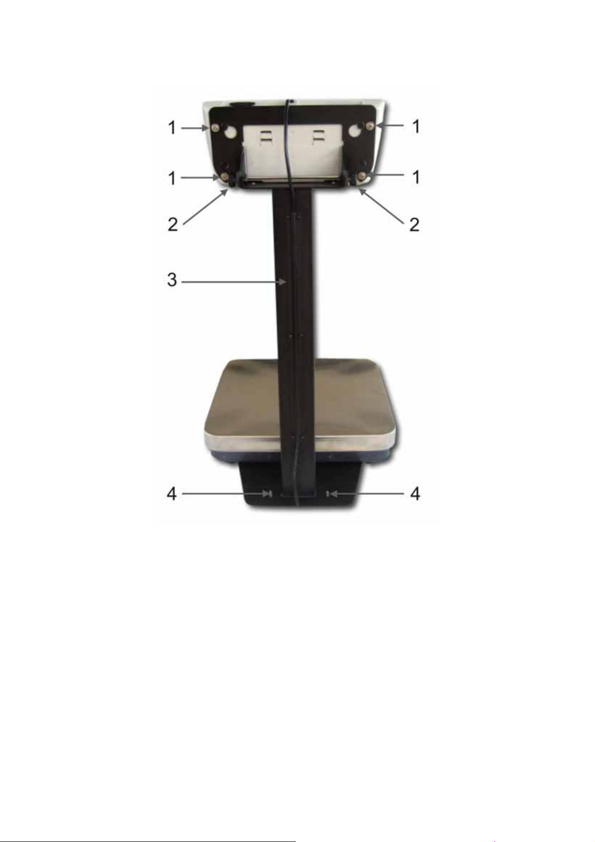
Abbildungsbeispiel Wägeplatte 315 x 305 x 75 mm
1. Schrauben zur Befestigung des Anzeigegerätes
2. Drehköpfe zur Positionierung des Anzeigegerätes
3. Kabelfach
4. Fußschrauben bis zum sicheren Stand eindrehen
DE-A10-IA-multi-1010 3
Page 4
GB
KERN DE-A10
Version 1.0 04/2010
Assembly instructions Tripod
Scope of delivery:
Qty. Component parts
1 Tripod
4 Screws „Display unit“
3 Screws „Tripod base“
Assembly of tripod.
Removing rubber plugs
Illustration example Weighing plate 315 x 305 x 75 mm
Detach cable. Attach the tripod base acc. to the illustration using three screws and
washers at the lower side of the balance. Ensure that the cable is not damaged nor
squeezed.
4 DE-A10-IA-multi-1010
Page 5

Illustration example Weighing plate 315 x 305 x 75 mm
1. Screws for fastening the display unit
2. Turning knobs for positioning the display unit
3. Cable box
4. Screw-in foot screws till they are safely fixed.
DE-A10-IA-multi-1010 5
Page 6

F
KERN DE-A10
Version 1.0 04/2010
Notice de montage Statif
Contenu de la livraison:
Qté. Composants
1 Statif
4 Vis „Afficheur“
3 Vis „pied de statif“
Montage du statif:
Retirer les bouchons en caoutchouc
Exemple d’illustration plateau de pesée 315 x 305 x 75 mm
Desserrer le câble. Fixer le pied du statif selon l’illustration à l’aide des trois vis et les
rondelles sur le côté inférieur de la balance. Veillez à ce que le câble ne soit pas
endommagée ou coincée.
6 DE-A10-IA-multi-1010
Page 7
Exemple d’illustration plateau de pesée 315 x 305 x 75 mm
1. Vis pour fixer l’afficheur
2. Boutons rotatifs pour positionner l’afficheur
3. Compartiment à câbles
4. Tourner les vis de pied jusqu’à avoir obtenu un emplacement sûre
DE-A10-IA-multi-1010 7
Page 8

E
KERN DE-A10
Versión 1.0 04/2010
Instrucciones de montaje Tripode
Volumen de entrega:
Pzas. Componentes
1 Tripode
4 Tornillos „Equipo indicador“
3 Tornillos „Pie de tripode“
Montaje del tripode:
Quitar tapones de caucho
Ejemplo de ilustración platillo de pesaje 315 x 305 x 75 mm
Aflojar cable. Montar el pie del tripode según la ilustración con los tres tornillos y
arandelas al lado inferior de la balanza. Observar que el cable no sea aplastado ni
dañado.
8 DE-A10-IA-multi-1010
Page 9

Ejemplo de ilustración platillo de pesaje 315 x 305 x 75 mm
1. Tornillo para montar el visualizador
2. Botones giratorios para posicionar el visualizador
3. Compartimiento de cables
4. Enroscar los tornillos hasta que estén bien asegurados.
DE-A10-IA-multi-1010 9
Page 10

I
KERN DE-A10
Versione 1.0 04/2010
Istruzioni di montaggio Treppiede
Volume di fornitura:
Pzo. Componenti
1 Treppiede
4 Viti „visualizzatore“
3 Viti „base del treppiede“
Montaggio del treppiede:
Togliere i tappi di gomma
Esempio di raffigurazione piatto di pesatura 315 x 305 x 75 mm
Allentare il cavo. Fissare la base del treppiede sec. ill. con le tre viti e le rondella nel lato
inferiore della bilancia. Attenzione a non danneggiare oppure schiacciare il cavo.
10 DE-A10-IA-multi-1010
Page 11

Esempio di raffigurazione piatto di pesatura 315 x 305 x 75 mm
1. Viti per fissare il visualizzatore
2. Bottoni girevoli per posizionare il visualizzatore
3. Scomparto cavi
4. Avvitare le viti di piede fino a ottenere uno stato sicuro
DE-A10-IA-multi-1010 11
Page 12

CZ
KERN DE-A10
Verze 1.0 04/2010
Stativ – návod na instalaci
Rozsah dodávky:
Kus Konstrukční díly
1 Stojan
4 Přišroubovat „Zobrazovací zařízení“
3 Přišroubovat „Nožku stativu“
Montáž stojanu:
Odstranit gumové zátky
Příklad zobrazení vážní plošina 315 x 305 x 75 mm
Povolit kabel. Nožku stativu připevnit podle obrázku třemi šrouby s podložkami ke spodní
straně váhy. Dbát na to, aby se kabel nezasekl nebo nepoškodil.
12 DE-A10-IA-multi-1010
Page 13

Příklad zobrazení vážní plošina 315 x 305 x 75 mm
1. Šrouby na upevnění zobrazovacího zařízení
2. Otočné hlavy na polohování zobrazovacího zařízení
3. Přihrádka na kabel
4. Šrouby nožiček přitáhnout tak daleko, aby se dosáhlo bezpečné stání.
DE-A10-IA-multi-1010 13
Page 14

NL
KERN DE-A10
Versie 1.0 04/2010
Montage-instructies Statief
Omvang van de levering:
Stuks Componenten
1 Statief
4 Schroeven „Afleesinstrument“
3 Schroeven „Statiefvoetstuk“
Montage statief:
Rubberproppen verwijderen
Afbeldingsvoorbeeld Weegplaat 315 x 305 x 75 mm
Kabel losmaken. Statiefvoetstuk volgens afb. met de 3 schroeven en onderlegplaatjes aan
de onderzijde van de weegschaal bevestigen. Let erop dat de kabel niet gekneld of
beschadigd raakt!
14 DE-A10-IA-multi-1010
Page 15

Afbeldingsvoorbeeld Weegplaat 315 x 305 x 75 mm
1. Schroeven voor de bevestiging van het afleesinstrument
2. Draaiknoppen voor de positionering van het afleesinstrument
3. Kabelvak
4. Voetschroeven indraaien totdat deze vastzitten.
DE-A10-IA-multi-1010 15
Page 16

P
KERN DE-A10
Versão 1.0 04/2010
Instruções de montagem Tripode
Conteúdo da entrega:
Unidade Componentes
1 Tripode
4 Parafusos „Equipamento visor“
3 Parafusos „Pé de tripode“
Montagem tripode:
Remover os tampões de borracha
Exemplo de ilustração prato de pesagem 315 x 305 x 75 mm
Afrouxar cabo. Fixar o pé de tripode segundo ilustração com os três parafusos e arruelas
à parte inferior da balança. Observar que o cabo não seja esmagado nem danificado.
16 DE-A10-IA-multi-1010
Page 17

Exemplo de ilustração prato de pesagem 315 x 305 x 75 mm
1. Parafuso para fixar o equipamento visor
2. Botões giratórios para posicionar o equipamento visor
3. Compartimento de cabos
4. Enroscar os parafusos de pé até estarem bem fixos.
DE-A10-IA-multi-1010 17
Page 18

PL
KERN DE-A10
Wersja 1.0 04/2010
Instrukacja instalacji statywu
Zawarte w dostawie:
Sztuk Podzespoły
1 Statyw
4 Śruby „Wyświetlacz“
3 Śruby „Nóżka statywu“
Statyw montażowy:
Usunąć gumową zatyczkę
Ilustracja przykładowa Płyta wagowa 315 x 305 x 75 mm
Rozwiązać przewód. Przymocować nóżkę statywu do spodu wagi tak, jak pokazano na
rysunku, za pomocą 3 śrub i podkładek. Uważać, aby przewód nie był przyciśnięty lub
uszkodzony.
18 DE-A10-IA-multi-1010
Page 19

Ilustracja przykładowa Płyta wagowa 315 x 305 x 75 mm
1. Śruby do zamocowania wyświetlacza
2. Głowice do ustawienia wyświetlacza
3. Schowek na przewód
4. Wkręcić nóżki tak, aby osiągnąć stabilność.
DE-A10-IA-multi-1010 19
Page 20

RUS
KERN DE-A10
Версия 1.0 04/2010
Инструкция по установке штатива
Состав комплекта поставки:
Кол-во Детали
1 Штатив
4 Винты "Индикатор"
3 Винты "Опора штатива"
Монтаж штатива:
Вынуть резиновые профили.
Пример изображения Плита весов 315 x 305 x 75 мм
Отсоединить кабель. Опору штатива согл. рис. закрепить 3 винтами и подкладными
шайбами к нижней стороне весов. Следить за тем, чтобы не пережать или не
повредить кабель.
20 DE-A10-IA-multi-1010
Page 21

Пример изображения Плита весов 315 x 305 x 75 мм
1. Винты для крепления индикатора
2. Поворотные рукоятки для позиционирования индикатора
3. Кабельный канал
4. Завинтите опорный винт до достижения устойчивого положения
DE-A10-IA-multi-1010 21
 Loading...