

Page 1

Keri Systems
User Manual
TAP100
Application Software
Page 2

TAP 100 Application Software Manual
© 1997 Keri Systems, Inc. ALL RIGHTS RESERVED
Document Number 01813-001, Revision 3.3
February, 1999
Keri Systems, ProxNet, TAP100, HPP-100 Hand-Held Programmer, PXL-100, OB-3, OB-9, and
KMM-40 Memory Module are trademarks of Keri Systems, Inc. Other product names are
trademarks or registered trademarks of their owners.
Keri Systems, Inc. reserves the right to change, without notice, product offerings or specifications.
No part of this publication may be reproduced in any form without written permission from Keri
Systems Inc.
Page 2 Revision 3.3
Page 3

TAP100 Application Software Manual
Contents
TAP100 SOFTWARE SETUP AND NAVIGATION 6
Introducing the TAP100 Software 6
Software Manual Conventions 6
Software Notes 6
Minimum System Requirements 6
Software Installation 7
Checking the PC System’s Time and Date 7
Starting the Program 9
Using the Menu System 10
The Menu Bar 10
Selecting a Menu Item 10
The Status Message Line 11
The Pull-Down Menus 11
The Network Communication Sprite 11
The Info and Quit Menu Options 11
The Info Option 11
The Quit Option 12
Dialog Boxes 12
SYSTEM CONFIGURATION 13
System Security 13
Setting/Changing a Unique Password 13
Entering Your PIN 14
Changing Your PIN 15
Configuring the TAP100 Software 17
Setting TAP100 Program Options 17
Enable/Disable Auditory Signals 17
Set Default Time Zone Values 17
The Default Time Zone Value for Disabled Access Cards 17
The Initial Enrollment Time Zone for New Cards 18
Set Event Log Viewing Options 18
Identifying the Database Files Directory 19
Configuring/Verifying Communications 20
Serial Port Configuration 20
Serial Port Connection 20
Modem Setup 21
Phone Hangup 22
Advanced Communication Setup Parameters 22
Verifying Network Operation 23
Revision 3.3 Page 3
Page 4

TAP 100 Application Software Manual
Configuring the ProxNet 26
Set the Timing Functions 26
Set the System Time and Date 26
Set Daylight Savings Time 27
Set Time Zones 27
Set Holidays 30
Configure the Readers 33
Opening the Reader Database 33
Query Status of a Reader 37
Global Secure 37
Setting Reader I/O Assignments 38
Setting an ‘OR’ I/O Assignment 39
Setting an ‘AND’ I/O Assignment 43
Clearing All I/O Assignments 46
CREATING/MAINTAINING A USER DATABASE 48
Create a Cardfile Database 48
Enrolling Cards 48
Open Cardholder File 50
Search for Cardholder Data 55
Voiding Cards 56
Get Network Card Data 57
Transaction Data File Management 58
Open Transactions File 59
Archiving a Transaction Log 63
Backup File 64
Get Network Transaction Data 64
ADVANCED COMMANDS 66
Monitor Network Events 66
Install New Reader 67
Lock/Unlock Commands 67
Lock A Reader 67
Unlock A Reader 68
Enable Global Lock/Unlock 68
Disable Global Lock/Unlock 69
Card Security Management Commands 70
Anti-Passback Amnesty 70
Set the Card Security Fence 70
APPENDICES 73
Status of Doors Table 75
Responding Nodes Table 78
Time Zone Table Worksheet 81
Glossary 82
Customer Support Information 83
Warranty Information 84
Page 4 Revision 3.3
Page 5

TAP100 Application Software Manual
Figures
FIGURE 1 - TAP100 MAIN MENU SCREEN 10
FIGURE 2 - INFO MENU OPTION INFORMATION 11
FIGURE 3 - SETUP MENU OPTION SCREEN 14
FIGURE 4 - UTILITY MENU OPTION SCREEN 15
FIGURE 5 - READERS MENU OPTION SCREEN 33
FIGURE 6 - CARDS MENU OPTION SCREEN 48
FIGURE 7 - TRANSACTIONS MENU OPTION SCREEN 58
Tables
TABLE 1 - PULL-DOWN MENU SUMMARY 11
TABLE 2 - AUTOMATIC LOCK/UNLOCK STATE 69
Revision 3.3 Page 5
Page 6

TAP 100 Application Software Manual
TAP100 Software Setup and Navigation
Introducing the TAP100 Software
The TAP100 Software provides access control programming for one or for multiple access control
sites, each with multiple access locations. It features complete alarm management and
programming flexibility for networks of up to 32 PXL-100 Control Units. Software programming is
performed through an easy to manage pull-down menu structure. For any given command, all
required information is displayed on the screen to provide easy set-up and management of your
access control system.
Software Manual Conventions
Bold Face
Information displayed by the computer will be shown in
.
For example:
Information you will be asked to type will be presented
For example:
Wherever appropriate, sample screen displays will be placed in the document, providing
information on the subject at hand.
C:\PROXNET>
cd \proxnet <ENTER>
Like This
.
Software Notes
Several of the commands in the menus in the TAP100 software refer to a Memory Module. The
KMM-40 Memory Module is an obsolete product, but the TAP100 software still supports its basic
operation. For those customers who already have and use KMM-40 Memory Modules, please
contact your Keri Systems dealer or installer for details on how to use the KMM-40 Memory
Module with the TAP100 software.
Minimum System Requirements
The TAP100 software requires a PC type of computer for operation. The following list defines the
minimum requirements for the PC system.
• PC-386 or greater microprocessor
• EGA color monitor or better
• 20 Mbyte hard drive
• 1 Mbyte RAM with at least 520K of free conventional memory
• 3.5” floppy disk drive
• serial port communications card
Optional requirements.
• mouse or track-ball pointing device
• parallel printer port
Page 6 Revision 3.3
Page 7

TAP100 Application Software Manual
Software Installation
The TAP100 software must be loaded and executed from the PC system’s hard drive. The
following set of instructions explain how to load the TAP100 software onto a PC system.
1. Start-up the computer.
C:\>
2. At the
3. Insert the TAP100 floppy disk into the 3.5” disk drive. Depending upon your system
configuration, this may be either the
assumes the 3.5” disk drive is the
substitute
4. Copy the TAP100.EXE program from the TAP100 floppy disk to the newly created ‘proxnet’
directory by typing:
DOS prompt, create a new directory by typing:
C:\> md proxnet <ENTER>
A:
drive or the B: drive. The following instruction
A:
drive; if it is the B: drive on your system, please
B:
for A:.
C:\>
cd \proxnet <ENTER>
C:\PROXNET>
5. Confirm that the TAP100 software was copied to the hard drive and is in the correct directory
by typing:
C:\PROXNET>
The computer should display:
copy a: TAP100.EXE <ENTER>
dir *.exe <ENTER>
TAP100 exe {file size} {creation date} {creation time}
{floppy disk related information}
This confirms the TAP100 software was copied to the hard drive and is in the correct directory. If
the computer does not confirm the transfer of the TAP100 software, please repeat this operation,
beginning with Step 1.
Checking the PC System’s Time and Date
Most of the functions within the TAP100 software are dependent upon having an accurate time
and date entered into the host PC system and, in turn, on the control units. Before starting the
TAP100 program, verify that the host PC system’s time and date are correct.
To verify/change the host PC system’s time:
C:\>
At the
DOS prompt, type:
C:\> time <ENTER>
The system will respond with:
Revision 3.3 Page 7
Page 8

TAP 100 Application Software Manual
Current time is XX : XX : XX . XX p/a
This lists the time on the host PC system in Hours : Minutes : Seconds . Hundredths of a
Second and then P.M. or A.M. If you are satisfied the system time is correct, type:
If you need to change the system time, enter the hours, minutes, and P.M. or A.M.
indicator to which you want to set the host PC system clock.
For example: To set the host PC system clock to 9:15 A.M., type:
Enter new time: 9:15 a <ENTER>
The host PC system’s clock will be set to the new time.
NOTE: All time commands are formatted to a 24-hour clock. For example: 6:15
P.M. becomes 18:15 hours.
To verify/change the host PC system’s date:
C:\>
At the
DOS prompt, type:
<ENTER>
C:\> date <ENTER>
The system will respond with:
Current date is Day-of-Week MM-DD-YYYY
This lists the date on the host PC system as the Day-of-the-Week followed by the Month,
Day, and Year. If you are satisfied the system date is correct, type:
<ENTER>
If you need to change the system date, enter the Month, Day, and Year to which you
want to set the host PC system date.
For example: To set the host PC system date to April 15, 1995, type:
Enter new date 04-15-95 <ENTER>
The host PC system’s calendar will be set to the new date.
Page 8 Revision 3.3
Page 9

TAP100 Application Software Manual
Starting the Program
Due to the manner in which PC systems allow executing programs to locate and access support
files, the TAP100 program must be executed from the PROXNET directory. This allows the
TAP100 program to locate and access all its support files. If the program is executed from
another directory, it will not be able to locate and access its support files and will not execute
correctly.
If the system is already in the PROXNET directory (identified by a DOS prompt of
C:\PROXNET>
), the program may be executed immediately by typing:
C:\PROXNET>
If the system is not in the PROXNET directory, regardless of which directory the system prompt is
at on the hard drive; to change to the PROXNET directory and begin executing the program, type:
C:\>
cd \proxnet <ENTER>
C:\PROXNET>
Upon execution, the program will clear the screen, identify itself, and request a password. The
following information will appear on the screen.
tap100 <ENTER>
tap100 <ENTER>
Keri Systems Transactions Analysis/ProxNet Program
VERSION x.xx Build Date: [date] Time: [time]
Enter your password:
When entering the program for the first time, the factory default password is ‘X X X X’ (all uppercase characters). Enter the program by typing:
Enter your password:
NOTE: You do not need to press
verification begins upon pressing the fourth character.
<ENTER>
when entering your password. Password
XXXX
If the program has accepted your password, it will immediately display the Main Menu screen. If
the password is not accepted, the program will exit and the DOS prompt will reappear.
If the program has
the factory-default password “X X X X’ is entered in UPPER-CASE. If the password is still not
accepted the password may have been changed. Instructions for resetting the password can be
obtained from your Keri distributor or system installer.
Revision 3.3 Page 9
not
accepted your password; repeat the steps from above, making sure that
Page 10

TAP 100 Application Software Manual
Using the Menu System
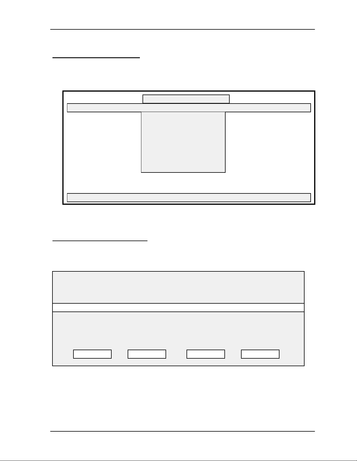
Once the password has been accepted, the TAP100 program begins, displaying the main menu.
TAP100 - Keri Systems, Inc.
Cards Transactions Readers Utilities Setup Info Quit
Menu Bar
Network Communication Sprite
‘Hot’ Key
Status Message Line
+
Press a hot key to make a selection.
Figure 1 - TAP100 Main Menu Screen
The Menu Bar
At the top of the main menu is the menu bar (see Figure 1). The menu bar consists of the quit
option, the TAP100 software information option, and five pull-down menus. Each pull-down menu
controls some facet of the access control system’s setup, operation, and maintenance.
Selecting a Menu Item
Three methods are available for navigating and selecting menu bar items.
Mouse/Trackball
•
used to move the TAP100 cursor around the screen to select a menu item. Once the
rectangular cursor is positioned over the desired item, click the left-button of the Mouse or
Trackball to select that item.
Arrow Keys
•
be used to move the TAP100 command highlight across the menu bar to select a menu item.
Once highlighted, the item can then be selected by pressing
‘Hot’ Keys
•
Figure 1). These are called “hot’ keys and are used as short-cuts to the desired menu item.
By pressing the letter on the PC’s keyboard corresponding to the highlighted ‘hot’ key, that
menu item is selected.
At any time when using a pointing device, the Arrow Keys, or the ‘Hot’ Keys, you can escape from
any command or sub-menu item by pressing the
Page 10 Revision 3.3
— If your PC is setup with a ‘pointing device,’ the pointing device can be
— For systems without a pointing device, the four arrow keys [! " # $] can
<ENTER>
— For each menu item, one letter will be highlighted in a contrasting color (see
<ESC>
(escape) key on the PC’s keyboard.
.
Page 11

TAP100 Application Software Manual
The Status Message Line
At the bottom of the menu screen is a status message line (see Figure 1). The status message
line displays information about the command in progress. When working with complex
commands, don’t neglect the status message line. It can assist you in tracking where you are in
the command or prompt you for the type of information to be entered.
The Pull-Down Menus
Selecting a pull-down menu from the menu bar will cause a list of items to appear. Typically,
these items will allow the operator to execute a command function. However, some items will, in
turn, cause a sub-menu to appear, supporting the more complex commands. Commands and
sub-menus will be explained in detail in a later section.
Table 1 - Pull-Down Menu Summary
Cards create a card file, enroll and void cards, assign access levels
Transactions create a transaction file, manage transaction/event data
Readers manage a single reader or a global set of readers, monitor a reader
Utilities manage time zone, PIN, and timing functions
Setup basic system configuration and communications port configuration
The Network Communication Sprite
Whenever an operation requires communication with networked control units a small, rotating
sprite appears in the lower left-hand corner of the main menu screen (see Figure 1). This sprite
continues rotating until communication has completed and control has been returned to the main
menu. When communication is being established, the sprite is white on a blue background. When
data is being transferred, the sprite is white on a green background.
The Info and Quit Menu Options
The two remaining items on the menu bar each perform one task.
The Info Option
The Info menu option displays the TAP100 software revision, the software copyright, and the
amount of computer memory available for the system software to use.
PROXNET/TAP-100 VERSION x.xx
© 1993-1995 Keri Systems, Inc.
xxxxxx bytes free memory
OK
Figure 2 - Info Menu Option Information
Revision 3.3 Page 11
Page 12

TAP 100 Application Software Manual
The Quit Option
The Quit menu option exits the TAP100 program and returns to DOS. To quit the TAP100
program, use your pointing device and select Quit. The following prompt box will appear.
This will end your session with TAP100.
DO YOU REALLY
WANT TO DO THIS?
YES/OK NO/CANCEL
To exit the program, use your pointing device and select YES/OK. To remain in the TAP100
program, use your pointing device and select NO/CANCEL to return to the main menu.
Dialog Boxes
Once a command has been selected from a menu or sub-menu, a dialog box will appear,
providing information and allowing the user to view and modify the parameters necessary to
perform a command. These dialog boxes follow certain conventions.
Red dialog boxes contain important warnings or confirmations that require acknowledgment by
the user before proceeding with the command. Please read this information before
acknowledging these boxes.
Dialog boxes with a series of data records or fields will have item highlighted in green. Use one of
the methods described above to select the item that you want to open for modification.
NOTE: If a list contains more records or fields than can be displayed on one screen, you
must use the arrow keys to scroll the list up and down to find the record or field you want.
Page 12 Revision 3.3
Page 13

TAP100 Application Software Manual
System Configuration
This section provides a logical progression of commands required for configuring your system for
an access control application. Please review this section in its entirety before configuring your
system. This section will cover system security, setting program operating options, configuring
system communications, and configuring the ProxNet system.
System Security
This section provides instructions for setting/changing the TAP100 software password, for
entering a Personal Identification Number (PIN), and for changing a PIN. You must enter the
correct password to be allowed access to the TAP100 program. You must enter the correct PIN
to make system configuration changes.
Setting/Changing a Unique Password
Before working with the TAP100 software, we recommend that you change from the factory
default password and set a unique password as soon as possible to ensure the security of your
PXL-100 access control system. These instructions also apply if you wish to change from one
unique password to a new unique password.
If you are already in the TAP100 program, use your pointing device to exit the program by
selecting Quit and then confirming the operation by selecting Yes.
This will leave you at the
NOTE: This is a lower-case ‘p.’
The system will display the following information on the screen.
C:\PROXNET>
C:\PROXNET>
DOS prompt. At the DOS prompt, type:
tap100 -p <ENTER>
Keri Systems Transactions Analysis/ProxNet Program
VERSION x.xx Build Date: [date] Time: [time]
Enter your password:
Enter the current password. If it is the system default, this will be ‘X X X X.’ If the password is
entered incorrectly, the screen will display:
Sorry your Password is Unacceptable.
The TAP100 software will then return to DOS.
If you password is accepted, the screen will display:
Please enter the NEW password:
Revision 3.3 Page 13
Page 14

TAP 100 Application Software Manual
Enter your new password.
NOTE: Passwords are ‘case-sensitive.’ This means a password may consist of both
upper- and lower-case letters. Be sure to enter the new password exactly as you want it
to be, paying close attention to the upper- and lower-cases.
Once entered, the program will ask you to confirm the new password by displaying:
Please enter it again just to be sure:
Again, carefully enter your new password. If the second entry matches the first, the screen will
display the following message and will then enter the program.
New Password installed.
If the two password entries do not match, the following error message will be displayed, and the
program will exit to DOS.
The two passwords did not match.
Your password has not been changed.
Just repeat this procedure, taking extra care to enter the new password correctly and identically,
when prompted.
Entering Your PIN
Before the TAP100 software will allow any system configuration changes, your Personal
Identification Number (PIN) must be entered. The software uses this number to identify an
operator with the authority to change the system configuration. Without the correct PIN number,
commands that affect system/network configuration or operation will not be transferred to the
system/network.
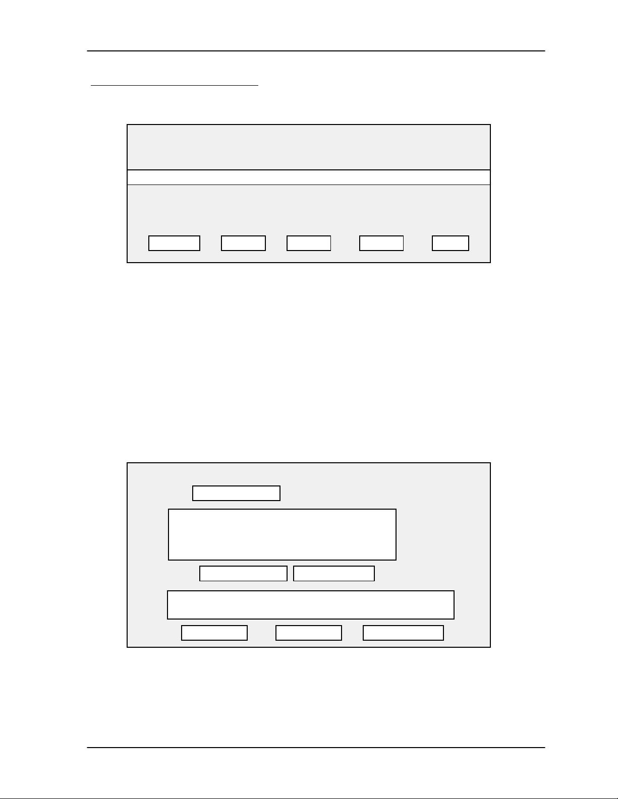
Using your pointing device, select Setup from the main menu. The following list directory of
commands will appear.
TAP100 - Keri Systems, Inc.
Cards Transactions Readers Utilities Setup Info Quit
Enter PIN
TAP options
Directory path
Port assignments
Serial connection
Modem setup
Advanced COM
Press a hot key to make a selection.
Figure 3 - Setup Menu Option Screen
Page 14 Revision 3.3
Page 15

TAP100 Application Software Manual
Using your pointing device, select Enter PIN. The following prompt box will appear, asking for
your 4 digit PIN.
PIN Entry
Enter your PIN: + + + +
The status message line will display:
Your PIN must be verified to enable communications with ProxLock.
The very first time the PIN is entered, it will be the factory default PIN: 0 0 0 0.
Enter your four digit PIN by typing:
0 0 0 0 <ENTER>
When your PIN is accepted, a prompt box will appear, confirming the PIN entry.
Your PIN entry was accepted.
OK
NOTE: You must be careful when entering your PIN. Any PIN will be accepted by the
system but only the correct PIN will allow you to actually set or make system
configuration changes.
Changing Your PIN
We recommend that you change from the factory default PIN and set a unique PIN as soon as
possible to ensure the security of your PXL-100 access control system.
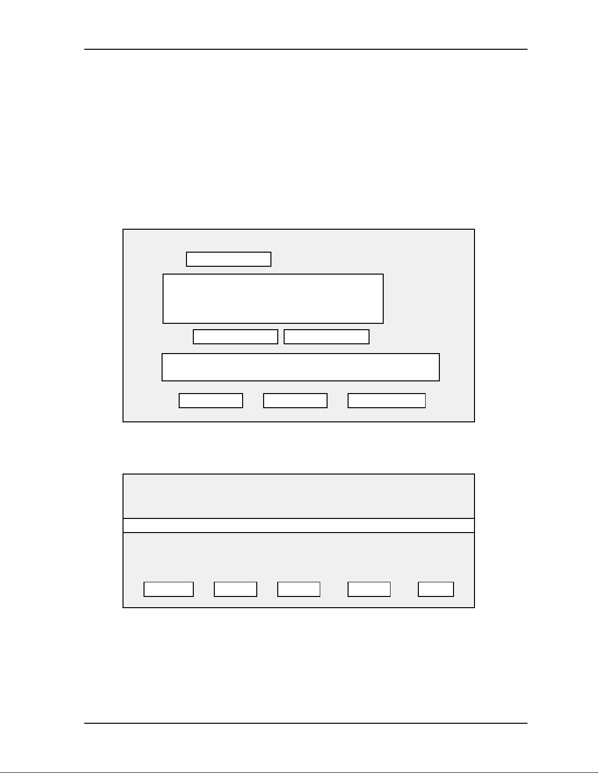
Changing your PIN is done from the Utilities menu.
TAP100 - Keri Systems, Inc.
Cards Transactions Readers Utilities Setup Info Quit
Time Zones
Holidays
I/O Assignments
Time and Date
Change System PIN
APB Amnesty
Erase Memory Module
Query Network
Phone Hangup
Press a hot key to make a selection.
Figure 4 - Utility Menu Option Screen
Revision 3.3 Page 15
Page 16

TAP 100 Application Software Manual
Use your pointing device and select Utilities, and then select Change System PIN. The following
prompt box will appear, asking for the new 4 digit PIN.
Set System PIN
Enter new PIN: + + + +
The status message line will display:
Change the system PIN to a new value.
Enter your new four digit PIN by typing the desired digits.
For example: To enter a new PIN of 1 2 3 4 type:
1 2 3 4 <ENTER>
The following prompt box will appear.
You are about to change the system PIN.
DO YOU REALLY
WANT TO DO THIS?
YES/OK
Use your pointing device and select YES/OK if you have entered the desired PIN. The TAP100
software will initiate communication with the control unit/readers on the network to inform them of
the new PIN. Once communication is complete, the system will confirm the new PIN with the
following prompt box.
Successfully changed system PIN.
You must now enter your PIN in the
SETUP menu to communicate with the
ProxLock master.
NOTE: If you have changed your PIN, you must re-enter your PIN as described in the
Entering Your PIN section on page 14, before the TAP100 software will allow any system
configuration changes.
If you have selected NO/CANCEL to exit the selection and cancel the new PIN, the system will
confirm the cancellation with the following prompt box.
NO/CANCEL
OK
System PIN not changed.
OK
Page 16 Revision 3.3
Page 17

TAP100 Application Software Manual
Configuring the TAP100 Software
This section provides instruction for setting TAP100 program options, identifying the directory
used for storing the program and the data files required by the system, configuring system
communications, configuring the ProxNet control units, and configuring the card readers.
Setting TAP100 Program Options
There are three TAP100 program options: enabling/disabling auditory signals (BEEPs), setting
default time zone values, and setting the event log viewing options.
Using your pointing device, select Setup from the main menu, and then select TAP options. A
prompt box will appear, displaying the three options.
Auditory signals
Timezone defaults
Event Log display
Enable/Disable Auditory Signals
Auditory signals are simply BEEPs from the computer’s speaker that prompt you to enter
information or alert you when a command has been accepted. Using your pointing device, select
A
uditory signals. A prompt box will appear, displaying the enable/disable option.
Sounds
( • ) Enable
( ) Disable
OK QUIT
The status message line will show:
Choose system sound state.
Use your pointing device and select Enable or Disable to meet your needs and select OK. Or,
select QUIT to exit the selection without making a change.
Set Default Time Zone Values
Setting the default time zone values allows you to set the default time zone value for disabled
access cards and to set the initial enrollment time zone for new cards.
The Default Time Zone Value for Disabled Access Cards
When an active card is disabled, it is automatically assigned to the time zone set by the default
time zone value for disabled access cards command. By setting this default time zone, you give
yourself the ability to disable an access card (and know it cannot have access to a controlled
area) without removing it from the database. This time zone should be configured as a ‘Never’
time zone. A ‘Never’ time zone is defined to not allow access at any time (the process for setting
time zones is described in a later section). You can then re-enable the card at a later date, simply
Revision 3.3 Page 17
Page 18

TAP 100 Application Software Manual
by assigning it to a working time zone. This is an easy and convenient way to disable a card for
someone who is on vacation or has taken a leave-of-absence. The card cannot be used while it is
assigned to this time zone. But, the card remains in the database, and can be quickly enabled
when the person returns.
NOTE: By factory default, time zone 7 has been configured as a ‘Never’ time zone.
The Initial Enrollment Time Zone for New Cards
The initial enrollment time zone for new cards automatically assigns the defined time zone to
newly enrolled cards. These cards stay at this time zone value until manually reassigned by the
software operator. This is an easy and convenient way to assign one time zone to a batch of
cards being enrolled; where one time zone value is set for typical users.
To set the default time zone values, use your pointing device, and select Timezone defaults. A
prompt box will appear, displaying the current time zone values.
Default Time Zones
Disabled Cards: 7
Initial Enrollment: 7
The status message line will display:
Specify timezones to be automatically assigned.
Using your pointing device, select the default time zone value that you want to set, and type in the
number.
For example: To set the Initial Enrollment time zone to 5, point to the Initial Enrollment field and
type:
5 <ENTER>
Set Event Log Viewing Options
The set event log viewing options command formats the cardholder and reader data in the event
log for viewing by a system operator. Using this command, you can format event data to display
the cardholder name with or without the card’s slot number and the reader’s name with or without
the reader’s ID number.
To set the event log viewing options, use your pointing device, and select Event Log display. A
prompt box will appear, displaying the current event log viewing options.
Event Log Viewing Options
( ) Show Slot Numbers and Cardholder Names
( ) Show Cardholder Names Only
( ) Show Reader Numbers and Names
( ) Show Names of Readers Only
OK QUIT
Page 18 Revision 3.3
Page 19

TAP100 Application Software Manual
The status message line will display:
Choose event display settings.
Use your pointing device and select the event log viewing options that meet your needs and
select OK. Or, select QUIT to exit the selection without making a change.
Identifying the Database Files Directory
When the TAP100 software was loaded onto the PC system, it was recommended that the
software be installed into a directory named
install the software in a different directory. In order for the TAP100 software to be able to locate
all of its database and system configuration files, you must identify the directory where the
software was installed (in DOS terms, this is called identifying the path).
To identify the database files directory, use your pointing device, and select Directory path. A
prompt box will appear, requesting the path where the TAP100 software is loaded on the PC host
system. It also displays the names of the system database and configuration files.
proxnet
Database Files
. Some system operators may decide to
Path:
Cardholder file name: chf.dbf
Log file name: log.dbf
System Configuration: sysinfo.cfg
The status message line will display:
Enter the directory path where the database files are located.
Type in the name of the directory where the TAP100 software is installed, and press
For example: To enter the factory recommended directory of
Path field and type:
c:\proxnet,
place the cursor in the
c:\proxnet <ENTER>
<ENTER>
.
Revision 3.3 Page 19
Page 20

TAP 100 Application Software Manual
Configuring/Verifying Communications
The next four commands in the setup menu deal specifically with configuring the usage of the
system’s communications network for the TAP100 software. These commands allow you to
assign which of the computer’s COM ports to use, define the use of the COM port (for serial
communication, modem communication, or for uploading or downloading memory module
information), define the modem setup information (if a modem is used), and set the
communication port’s interrupt vectors and port addressing.
Serial Port Configuration
The serial port configuration command asks you to define the serial COM port to use for each of
the three possible communication options.
To configure the serial port, use your pointing device, and select Port assignments. A prompt box
will appear, displaying the three possible communication devices and displaying the factory
default values. For all three communication devices, the factory default is COM port 1.
Port Configuration
Prox port: 1
Modem port: 1
Memory module port: 1
ENTER = accept ESC = quit
The status menu line will display:
Select serial port assignments.
To change a port assignment, use your pointing device and move the blinking cursor to the port
value to be changed, type the new number, and press
For example: To change the proxnet communication port to 2, place the cursor in the field to the
right of the Prox port call-out and type:
<ENTER>
.
2 <ENTER>
Serial Port Connection
The serial port connection command allows you to define the use of the serial port: for serial
communication in a PXL-100 network, modem communication (for remote communication with a
PXL-100 network), or for uploading or downloading memory module information.
To define the use of the serial port, use your pointing device, and select Serial connection. A
prompt box will appear, displaying the three possible communication devices. The factory default
is to enable the local prox network on COM1.
Page 20 Revision 3.3
Page 21

TAP100 Application Software Manual
Serial Port Connection
( • ) Local Prox Network on COM1
( ) Phone connection/modem on COM1
( ) Memory Module on COM1
OK QUIT
The status message line will display:
Select a new connection.
NOTE: The Memory Module is an obsolete hardware option. It is supported for those
customers who already have Memory Modules in use. For details on Memory Module
operation, please contact your Keri dealer or system installer.
Use your pointing device and select the serial port connection mode that meet your needs and
select OK. Or, select QUIT to exit the selection without making a change.
Modem Setup
The modem setup command asks you to define the modem initialization string and the telephone
dialing method: pulse or tone.
NOTE: Prior to executing the modem setup command, the master PXL-100 control unit
must be set to the modem mode with the modem connected. Refer to the HPP-100 Hand
Held Programmer manual for instructions on setting the PXL-100 to modem mode.
NOTE: The modem used for communication must be capable of operating at 9600 baud
or greater, and its error correction and data compression features must be disabled.
To setup the modem, use your pointing device, and select Modem setup. A prompt box will
appear, displaying the two modem setup commands.
Initialization String
Dialing Method
To set the initialization string, use your pointing device and select Initialization String. A prompt
box will appear, displaying the factory default modem initialization strings.
Modem Initialization String
Your init string: S0=0
TAP init string: &F&C1&D2E0V1Q0
Use your pointing device, move the blinking cursor to the beginning of the ‘Your init string’ field,
and type in your modem’s initialization string.
For example: To enter a possible modem initialization string for a US Robotics 14.4 Sportster
modem, place the cursor in the correct field and type:
ATE0&A2B0&N0S10=15&B1
Revision 3.3 Page 21
Page 22

TAP 100 Application Software Manual
To set the phone dialing method, use your pointing device and select Dialing Method. A prompt
box will appear, displaying the two options.
Dialing Method
( • ) Tone
( ) Pulse
OK QUIT
The status message line will display:
Select tone or pulse dialing.
Use your pointing device and select the dialing method that meets your telephone system and
select OK. Or, select QUIT to exit the selection without making a change.
Phone Hangup
To ensure proper disconnect of the telephone line following modem operations, use the phone
hangup command. Use your pointing device and select Utilities, and then Phone Hangup. The
following prompt box will appear.
You are about to hang up the phone.
DO YOU REALLY
WANT TO DO THIS?
YES/OK
If you are not ready to hang-up the phone, use your pointing device and select NO/CANCEL to
exit the selection without disconnecting the modem. Otherwise, use your pointing device and
select YES/OK. The modem will be disconnected from the telephone line.
NO/CANCEL
Advanced Communication Setup Parameters
The advanced com command asks you to define the interrupt request values and port addresses
for the four communication ports (COM1 through COM4). This command should be used
carefully. You must know the correct values to enter in these fields; an incorrect entry can entirely
disable your PC’s communication ability.
To define the interrupt request values and port addresses for the four communication ports, use
your pointing device, and select Advanced COM. A prompt box will appear with a table displaying
the factory default com port interrupt request values and port addresses.
Page 22 Revision 3.3
Page 23

Advanced COM Setup
TAP100 Application Software Manual
PORT IRQ
COM1 4 03F8
COM2 3 02F8
COM3 4 03E8
COM4 3 02E8
ENTER = accept ESC = quit
F1 = restore default values
The status message line will display:
Customize IRQ assignments and interrupt service vectors.
To exit this command without making a change, press <ESC>. To restore the IRQ and ADDR
values to the factory default, press <F1>. To change an IRQ/ADDR value, use your pointing
device, move the blinking cursor to the IRQ or ADDR fields, and type in the IRQ and ADDR
values for your PC system.
For example: To change COM4 to IRQ 7, ADDR 0FF8, place the cursor in the COM4, IRQ field
and type:
ADDR
7
Then place the cursor in the COM4, ADDR field and type:
0FF8 <ENTER>
Verifying Network Operation
If the TAP100 software has been configured for COM port/serial communication, this command is
used to verify the access control system network is communication properly. To verify network
communication, use your pointing device and select Utility and then Query Network. The status
message line will state:
Initiating communication with local network on COM1 . . . please wait.
Once communication has been established, the status message line will go blank and the
following prompt box will appear.
Network Information
System ID = 0
Net Faults = 0
P/O Self Test Fail = 0
P/O Count = 0
Net Security = Secured
Status of Doors = 00000000
Responding Nodes = 00000001
Favorite Nodes = 00000001
Links in Bindery = 0
OK
Revision 3.3 Page 23
Page 24

TAP 100 Application Software Manual
The System ID is the address of the master control unit on the network.
Net Faults is a counter keeping track of the number of times there is a network failure or a control
unit goes off-line. If power is removed from a control unit, it will go off-line and the counter will be
incremented. A high number in this field may indicate a loose wire somewhere in the
communication network.
P/O Self Test Fail is a counter keeping track of the number of times there has been a power-on
RAM check failure. This number should be 0. A high number in this field indicates the control
unit’s RAM is being corrupted. This may be due to electrical events such as sparks or static
charges, or it may be due to magnetic interference.
P/O Count is a counter keeping track of the number of times the system’s power has been cycled
on. A high number in this field indicates the control unit’s power is being cycled off and on. Verify
the control unit’s power connections are secure and that its power source is operating properly.
Net Security identifies if all doors on the network are secured or unsecured per the global secure
command (see the Global Secure command on page 38).
Status of Doors identifies how many and which doors are secured. An eight digit hexadecimal
value is displayed in the status of doors field. To determine which doors are secured, a
conversion process must be applied to each digit in that hexadecimal value.
Each hexadecimal digit in the status of doors field represents four doors. Working from right-to-
left, the first digit represents doors 1 through 4, the second digit represents doors 5 through 8,
and so on to the eighth digit representing doors 29 through 32.
Each hexadecimal digit must be converted to binary to determine specifically which doors are
secured. Again, working from right-to-left, convert the hexadecimal digit to its binary value. The
first digit in the binary value refers to the first door in the group (i.e. a group of doors 5 through 8,
the first digit would refer to door 5), the second digit refers to the second door (6), the third digit to
the third door (7), and the fourth digit to the fourth door (8). Wherever there is a zero in the binary
value, that indicates the corresponding door is secured.
To simplify this process, a table, breaking down this conversion process is provided in Appendix
1. By working the status of doors value through the table in Appendix 1, you can easily determine
which doors are secured.
Responding Nodes identifies how many and which controllers are responding to the network in a
manner similarly to the status of doors value. An eight digit hexadecimal value is displayed in the
responding nodes field. To determine how many and which controllers are responding, a
conversion process must be applied to each digit in that hexadecimal value.
Each hexadecimal digit in the responding nodes field represents four controllers. Working from
right-to-left, the first digit represents controllers 1 through 4, the second digit represents
controllers 5 through 8, and so on to the eighth digit representing controllers 29 through 32.
Each hexadecimal digit must be converted to binary to determine specifically which controllers
are on-line and active. Again, working from right-to-left, convert the hexadecimal digit to its binary
value. The first digit in the binary value refers to the first controller in the group (i.e. a group of
controllers 5 through 8, the first digit would refer to controller 5), the second digit refers to the
second controller (6), the third digit to the third controller (7), and the fourth digit to the fourth
controller(8). Wherever there is a one in the binary value, that indicates the corresponding
controller is responding to the network.
Page 24 Revision 3.3
Page 25

TAP100 Application Software Manual
To simplify this process, a table, breaking down this conversion process is provided in Appendix
2. By working the responding nodes value through the table in Appendix 2, you can easily
determine which controllers are responding to the network
Favorite Nodes, by factory definition, is always set to 00000001.
Links in Bindery identifies the number of reader I/O links that have been defined for the system.
For information on I/O links, see the Setting Reader I/O Assignments section on page 38.
When you are finished viewing this information, use your pointing device and select OK.
Revision 3.3 Page 25
Page 26

TAP 100 Application Software Manual
Configuring the ProxNet
In this section, we will describe the configuration of the ProxNet: setting all system timing
functions, configuring the reader database, and defining the reader’s I/O assignments.
Set the Timing Functions
The following commands deal with setting system time, date, time zone, and holiday zone
functions.
Set the System Time and Date
Synchronizing the time and date between access control units on the network and the host
computer allows for accurate time/date tracking of events. To set the time and date for the control
units on the network to match that of the host computer, use your pointing device and select
U
tility and then Time and Date. The status message line will state:
Initiating communication with local network on COM1 . . . please wait.
Once communication has been established, the following prompt box will appear.
SET SYSTEM TIME AND DATE
When you hit ENTER, the time and date
of the ProxLock system will be set to
the computer’s time and date.
Press ESC to quit without changing.
Press
<ESC>
the TAP100 software will set the access control unit’s time and date to match that of the host
computer. The software will confirm the operation completed successfully by displaying the new
time.
For example: If the computer’s time is 17:35:45 (5:35 P.M. and 45 seconds) and its date is July 4,
1995, the following information will be displayed.
to exit the operation without changing the time and date. Or, press
SET SYSTEM TIME AND DATE
Setting system time and date.
Sending time: 17:34:45
Sending date: 07/04/95, Tue
PRESS ANY KEY TO CONTINUE
<ENTER>
and
NOTE: All time commands are formatted to a 24-hour clock. For example: 6:15 P.M.
becomes 18:15 hours.
Page 26 Revision 3.3
Page 27

TAP100 Application Software Manual
Set Daylight Savings Time
To enable or disable the one-hour daylight savings time change, use your pointing device and
select Utility and then Daylight Savings. The following prompt box will appear.
Daylight Savings Mode
( ) Enabled
( • ) Disabled
OK QUIT
The status message line will display:
Choose daylight savings time state.
Use your pointing device and select Enabled or Disabled to match the current daylight savings
mode and select OK. Or, select QUIT to exit the selection without making a change.
NOTE: Daylight Saving Time for all U.S states, the District of Columbia, and U.S.
possessions begins at 2 A.M. on the first Sunday in April and ends at 2 A.M. on the last
Sunday in October.
Set Time Zones
A time zone is a defined block of time that is assigned to a card to allow access. A time zone
consists of either an all encompassing categorization of Never or Always, or it consists of a
definition of the hours and days of the week that access is allowed. Careful setting of the time
zones is critical to the proper operation of your access control system. It is through the use of
time zones that automatic entry and automatic securing of your controlled areas are set.
To begin the set time zone process, use your pointing device and select Utility and then Time
Zones. The following prompt box will appear with the factory default time zone values.
TIME ZONES
TZNUM ACCESS PERIOD
0Always
1 07:00 – 18:00 So Mo Tu We Th Fr Sa
2 15:00 – 00:30 So Mo Tu We Th Fr Sa
3 23:30 – 07:30 So Mo Tu We Th Fr Sa
4 07:00 – 16:00 So Mo Tu We Th Fr Sa
5 23:00 – 03:00 So Mo Tu We Th Fr Sa
6 External
7 Never (fixed time zone)
8 Never
MODIFY PRINT SEND QUIT
DAYS OF THE WEEK
In the above prompt box, TZNUM refers to the identification number for a time zone, ACCESS
PERIOD refers to the period of time that time zone will allow access to the controlled area, and
DAYS OF THE WEEK refers to the days of the week to which the access period is applied.
Revision 3.3 Page 27
Page 28

TAP 100 Application Software Manual
For example: TZNUM 1 has an access period of 07:00 to 18:00 (7 A.M. to 6 P.M.) on Monday
through Friday.
An access card assigned to TZNUM 1 will be allowed access between these hours Monday
through Friday. If used at any other time, an access card assigned to TZNUM 1 will cause an
alarm event.
NOTE: Time zones 0, 6, and 7 have reserved functions. An access card assigned to time
zone 0 will always be allowed access to the controlled area. An access card assigned to
time zone 7 will never be allowed access to the controlled area. Time zone 6 has been
reserved for external purposes.
Before setting the time zones for your access control system, please spend some time and map
out all time zone usage possibilities for your application. Not only do you need to consider the
variety of standard access hours for employees and customers, but you also need to take into
account such requirements as:
• janitorial personnel, who may require late night/early morning hours
• service/repair personnel, who may require access at any time
• supervisory/management personnel, who may require extended access hours
• swing shift, graveyard shift, and flex-time personnel, all with unique access requirements.
A time zone worksheet has been provided in Appendix 2 to assist you in this planning.
Once you have determined your time zone requirements, you can begin setting them into the
system. Remember, time zones 0, 6, and 7 cannot be changed. You can change the factory
default assignments in time zones 1 through 5, or leave these and start fresh with time zone 8. In
either case, the process for changing or creating a time zone is the same.
The easiest way to describe the time zone assignment process is through an example. In this
example, we will set time zone 8 for cards used by a janitorial service. This service performs its
work between 8 P.M. and 11 P.M., Monday through Friday.
Use your pointing device and select the time zone in which you want to set values – in this case,
time zone 8. The time zone will be identified by a bright highlight bar. Use your pointing device
and select Modify. The following prompt box will appear.
Modify Time Zone 8
Special Time Zone
( ) Never
( ) Always
( ) Extended
[ ] Sun Begin 00:00
[ ] Mon End 00:00
[ ] Tue
[ ] Wed
[ ] Thu
[ ] Fri
[ ] Sat
Definable Time Zone
OK QUIT
To switch between windows use LEFT, RIGHT Arrow keys
To move the cursor use UP, DOWN Arrows or Hotkeys
To select days of the week use SPACE BAR
Page 28 Revision 3.3
Page 29

TAP100 Application Software Manual
When this box appears, it will display either the Special Time Zone window or the Definable Time
Zone window. Use the Left and Right arrow keys to toggle between windows. For this example,
toggle to the Definable Time Zone window.
Use your pointing device and select Monday, Tuesday, Wednesday, Thursday, and Friday. As
you select these days, an “X” will appear between the brackets for that day. Now use your
pointing device and select the Begin time; type:
20:00
Now use your pointing device and select the End time; type:
23:00
The prompt box should now appear like this.
Modify Time Zone 8
Special Time Zone
( ) Never
( ) Always
( ) Extended
OK
To switch between windows use LEFT, RIGHT Arrow keys
To move the cursor use UP, DOWN Arrows or Hotkeys
To select days of the week use SPACE BAR
Finally, if you wish to exit without making these changes, use your pointing device and select
QUIT. If you are satisfied with your changes, use your pointing device and select OK. This will
return you to the original time zone table where your changes should now appear.
TZNUM ACCESS PERIOD
0Always
1 07:00 – 18:00 So Mo Tu We Th Fr Sa
2 15:00 – 00:30 So Mo Tu We Th Fr Sa
3 23:30 – 07:30 So Mo Tu We Th Fr Sa
4 07:00 – 16:00 So Mo Tu We Th Fr Sa
5 23:00 – 03:00 So Mo Tu We Th Fr Sa
6 External
7 Never (fixed time zone)
8 20:00 – 23:00 So Mo Tu We Th Fr Sa
[ ] Sun Begin 20:00
[X] Mon End 23:00
[X] Tue
[X] Wed
[X] Thu
[X] Fri
[ ] Sat
TIME ZONES
DAYS OF THE WEEK
Definable Time Zone
QUIT
MODIFY
Revision 3.3 Page 29
PRINT SEND QUIT
Page 30

TAP 100 Application Software Manual
Repeat this process for each time zone required to meet your application’s needs.
Once all time zone entries have been set, you can PRINT a hard copy of the time zone table.
This will allow you to review the entire time zone entry table one last time before sending this
information to the control units. To print a hard copy of the time zone table, use your pointing
device and select PRINT. The following prompt box will appear.
Print Job Progress
0% 100%
Press ESC to abort the print job.
As the time zone table is being printed, the status bar in this prompt box will monitor how far
along the print process is. When the print job has finished, you can review all time zone entries
and verify they are correct. The printout will appear like this.
TAP-100 VERSION X.XX Time Zones
DATE TIME page #
==========================================================
TZNUM ACCESS PERIOD DAYS OF THE WEEK
0Always
1 07:00 18:00 — Mo Tu We Th Fr —
2 15:00 00:30 — Mo Tu We Th Fr —
3 23:30 07:30 Su Mo Tu We Th — —
4 07:00 16:00 Su Mo Tu We Th Fr Sa
5 23:00 03:00 — Mo — We — Fr —
6 External
7 Never
8 20:00 23:00 — Mo Tu We Th Fr —
• • •
31 Never
Once you have reviewed the time zone table and are satisfied with all its entries, you must send
this information to all control units on the network. Use your pointing device and select SEND.
The Status Message Line will display:
Initiating communication with local network on COM1 . . . please wait.
Once communication is established, the Status Message Line will display:
Sending time zone information to ProxLock . . . please wait . . .
When this process is complete, the Status Message Line will display:
Done.
Set Holidays
Holidays are defined by the TAP100 software as special days when the standard time zone rules
do not apply. On holidays, no access is allowed except for cards configured with time zone 0.
Before entering holidays, take some time and list all the dates to be considered as holidays by the
Page 30 Revision 3.3
Page 31

TAP100 Application Software Manual
system. To set holidays, use your pointing device and select Utility and then Holiday. The
following prompt box will appear.
HOLIDAY SCHEDULE
NUM DATE
1
2
3
4
5
6
7
8
All holiday dates must be entered in a month/day format with two characters for the month and
two characters for the day (i.e. January 1 is entered as 01/01). All unassigned holiday dates will
be listed with a date of 00/00. Use your pointing device, select the first holiday entry date, and
then select Modify. The following prompt box will appear.
Month: 00
Date: 00
OK QUIT
Enter two characters for the month, followed by two characters for the day. If you need to correct
an entry, use the arrow keys to select the character and type over it with the correct character. If
you wish to exit without entering this holiday, use your pointing device and select QUIT. If you are
satisfied with your entry, use your pointing device and select OK. This will return you to the
original holiday table where your change should now appear.
MODIFY
PRINT
SEND
QUIT
Repeat this process for each holiday required to meet your application’s needs.
Once all holiday entries have been set, you can PRINT a hard copy of the holiday table. This will
allow you to review the entire holiday entry table one last time before sending this information to
the control units. To print a hard copy of the holiday schedule table, use your pointing device and
select PRINT. The following prompt box will appear.
Print Job Progress
0% 100%
Press ESC to abort the print job.
As the holiday schedule table is being printed, the status bar in this prompt box will monitor how
far along the print process is. When the print job has finished, you can review all holiday schedule
entries and verify they are correct. The printout will appear like this (a possible holiday schedule
for 1995).
Revision 3.3 Page 31
Page 32

TAP 100 Application Software Manual
TAP-100 VERSION X.XX Holiday Schedule
DATE TIME page #
==========================================================
NUM DATE
1 01/01
2 04/16
3 05/29
4 07/04
5 09/04
6 11/23
7 11/24
8 12/24
9 12/25
10
• • •
20
Once you have reviewed the holiday table and are satisfied with all its entries, you must send this
information to all control units on the network. Use your pointing device and select SEND. The
status message line will display:
Initiating communication with local network on COM1 . . . please wait.
When this process is complete, the status message line will display:
Done.
NOTE: Some holiday dates change from year-to-year (i.e. Easter, Thanksgiving). We
recommend you review and update the holiday schedule prior to the beginning of a new
year to ensure proper holiday coverage.
Page 32 Revision 3.3
Page 33
TAP100 Application Software Manual
Configure the Readers
In this section we will the instructions for entering all the information required to create a reader
database for day-to-day operation. We will also look at commands for adding a new reader to an
existing database and at commands for globally securing the readers.
TAP100 - Keri Systems, Inc.
Cards Transactions Readers Utilities Setup Info Quit
Open reader database
Query status of a reader
Lock a reader
Unlock a reader
Install new reader
Enable global lock/unlock
Disable global lock/unlock
Global secure
Press a hot key to make a selection.
Figure 5 - Readers Menu Option Screen
Opening the Reader Database
The open reader database command, allows you to define all the day-to-day operating
parameters for each reader. Use your pointing device and select Readers and then Open readers
database. The following prompt box will appear.
READERS
OPEN UNLOCK ALU SUP ALARM
RDR NAME (Ant A) TIME TIME ZONES APB I/O CTRL POL
1 no name 1-A 20s 5s 7 7 N N Y N/C
2 no name 1-A 20s 5s 7 7 N N Y N/C
3 no name 1-A 20s 5s 7 7 N N Y N/C
4 no name 1-A 20s 5s 7 7 N N Y N/C
5 no name 1-A 20s 5s 7 7 N N Y N/C
• • •
MODIFY PRINT SEND QUIT
The easiest way to describe the reader assignment process is through an example. In this
example, we will define reader 4 as an employees only entry/exit door with two reader antennas.
One of these reader antennas will be used to allow/monitor entrances, the other to allow/monitor
egresses.
Use your pointing device and select the reader in which you want to set values – in this case,
reader 4. The reader will be identified by a bright highlight bar. Use your pointing device and
Revision 3.3 Page 33
Page 34

TAP 100 Application Software Manual
select Modify. The following prompt box will appear with a flashing cursor at the first entry of the
table.
Modifying Reader 4
Reader Name A
Reader Name B
Open time (seconds) 20
Unlock time (seconds) 5
Local APB enabled (Y/N) N
Auto-Unlock time zone 1 07
Auto-Unlock time zone 2 07
Supervised I/O (Y/N) N
Alarm Control (Y/N) N
Input Normal Polarity (O/C) C
Press ENTER to accept, ESC to abort
The Reader Name A entry allows you to define a short description for that reader; in this
application it is the employee entrance. Type:
EMP ENTRANCE
Use your pointing device and select the Reader Name B entry. The Reader Name B entry is used
when you have two reader antennas attached to the same control unit to control both entrance
and egress. This is true for this example. For Reader Name B, type:
EMP EXIT
This allows you to keep track of when an employee’s access card entered or exited through this
door.
NOTE: There is a 16 character maximum for the Reader Name description. Please use
short names or descriptive abbreviations when entering reader names.
The Open time is the number of seconds a door may be held open for entrance or egress before
an alarm event is generated. The software default is 20 seconds, but we will allow an employee
40 seconds to use the door before an alarm event is generated. Use your pointing device and
select the Open time. Type:
40
The Unlock time is the number of seconds the control unit holds the lock relay open – essentially
the amount of time that an access control door will be held unlocked beginning from when an
access control card is presented to the reader. The software default is 5 seconds, but we will
have the control unit hold the lock relay open for 15 seconds. Use your pointing device and select
the Unlock time. Type:
15
The next entry defines if local APB (versus network APB) is enabled. APB stands for antipassback. This feature is used to ensure one-card/one-way access into and then out of a
controlled area. For local APB, an authorized card presented to an access reader will allow
access, but will not work again for access until presented to the egress reader, or until either the
control unit is reset with the anti-passback amnesty command (see the anti-pass back amnesty
Page 34 Revision 3.3
Page 35

TAP100 Application Software Manual
command on page 70) or 24 hours have passed. This prevents a person from entering a
controlled area with an access card and then “passing” that card back to another person to use
for entry. In network APB, there is one access reader and multiple egress readers; all other rules
apply. The factory default is to disable local APB, but for this example we will enable local APB.
Use your pointing device and select local APB. Type:
Y
The auto-unlock time zone command controls the automatic unlocking of a reader’s door by time
zone. For instance, if time zone 10 is defined to allow employees access between 6 A.M. and 7
P.M., Monday through Friday; by setting the auto-unlock time zone to 10, the reader will
automatically unlock its door for these hours on these days. Use your pointing device and select
auto-unlock time zone 1. Type:
10
A second auto-unlock time zone is provided for maximum flexibility. For instance, different
operating hours may be set for weekends. If time zone 20 is defined to allow employees access
between 9 A.M. and 5 P.M., Saturday and Sunday; by setting the auto-unlock time zone to 20,
the reader will automatically unlock its door for these hours on these days. Use your pointing
device and select auto-unlock time zone 2. Type:
20
NOTE: To support situations where a user presents a valid card but decides not to enter
or is delayed in entering, the system does not impose anti-passback checking until the
user actually opens the door to enter. If the user does not open the door, the same card
can be presented again to the reader without being considered an anti-passback
violation.
Use the supervised I/O entry to tell the TAP100 software if the control unit associated with that
reader uses supervised I/O (a 3-state or 4-state input). For this feature to be used, an OB-3
Input/Output and Alarm Panel Control option board or an OB-9 Dual Door Control option board
must have been installed on the reader’s control unit. The factory default is for this to be disabled,
but we will enable it. Use your pointing device and select supervised I/O. Type:
Y
Use the alarm control entry to tell the TAP100 software if that reader’s control unit has been
configured to use the alarm control panel feature. For this feature to be used, an OB-3
Input/Output and Alarm Panel Control option board must have been installed on the reader’s
control unit and a security fence card slot must be set (refer to the Security Fence command on
page 70). The factory default is for this to be disabled, but we will enable it. Use your pointing
device and select alarm control. Type:
Y
And finally, the input normal polarity entry is used to inform the TAP100 software if the polarity of
the input relay is set to normally open or normally closed. The factory default is for a normally
closed relay (which will open for an alarm event) so leave this as C.
With all these changes, the modifying reader prompt box should appear as follows.
Revision 3.3 Page 35
Page 36

TAP 100 Application Software Manual
Modifying Reader 4
Reader Name A EMP ENTRANCE
Reader Name B EMP EXIT
Open time (seconds) 40
Unlock time (seconds) 20
Local APB enabled (Y/N) Y
Auto-Unlock time zone 1 07
Auto-Unlock time zone 2 07
Supervised I/O (Y/N) Y
Alarm Control (Y/N) Y
Input Normal Polarity (O/C) C
Press ENTER to accept, ESC to abort
Once all reader database entries have been made, you can PRINT a hard copy of the readers
database. This will allow you to review the entire reader database one last time before sending
this information to the control units.
To print a hard copy of the reader database, use your pointing device and select PRINT. The
following prompt box will appear.
Print Job Progress
0% 100%
Press ESC to abort the print job.
As the reader database is being printed, the status bar in this prompt box will monitor how far
along the print process is. When the print job has finished, you can review all reader database
entries and verify they are correct. The printout will appear like this.
TAP-100 VERSION X.XX Door/Reader Information
DATE TIME page #
==========================================================
RDR NAME (Ant A) TIME TIME ZONES APB I/O CTRL POL
1 no name 1-A 20s 5s 7 7 N N Y N/C
2 no name 1-A 20s 5s 7 7 N N Y N/C
3 no name 1-A 20s 5s 7 7 N N Y N/C
4 EMP ENTRA 40s 20s 7 7 Y Y Y N/C
5 no name 1-A 20s 5s 7 7 N N Y N/C
• • •
Once you have reviewed the reader database and are satisfied with all its entries, you must send
this information to all control units on the network. Use your pointing device and select SEND.
The status message line will display:
Initiating communication with local network on COM1 . . . please wait.
Page 36 Revision 3.3
Page 37

TAP100 Application Software Manual
When this process is complete, the status message line will display:
Done.
Query Status of a Reader
The query status of a reader command gives a table of all current operating parameters defined
for that reader. To query the status of a reader, you must know the address of the reader to
query. Use your pointing device and select Readers and then Query status of a reader. The
following prompt box will appear.
Reader number to query: (1-32) ___
For example: To query the status of reader 4 as entered in the reader database above, type:
4 <ENTER>
Communication will begin with the selected reader and the Status Message Line will display:
Initiating communication with local network on COM1 . . . please wait.
Once communication is complete, the following prompt box will appear.
Information on Reader 4
Firmware Version: 2.23
System ID: 0
Power On Count: 0
Watchdog Count: 0
POST Fail Count: 0
Dual Door: Y
Local Anti-Passback: Y
Open Time: 40seconds
Unlock Time: 20seconds
Door Status: Secured
Card Holders: 3
Events in Log: 17
Temporaries: 0
Reader’s Date: Tue 07/04/95
Reader’s Clock: 13:30:54
Press any key when finished.
Review this table for the status information of the requested reader.
Global Secure
The global secure command locks all doors on the network at a specified time of day, except for
those doors that are programmed to be unlocked per the auto-unlock function of the reader
database. This ensures that any door not specifically programmed to be open is automatically relocked once a day. The factory default value for global secure is 20:00 hours (8 P.M.).
Revision 3.3 Page 37
Page 38

TAP 100 Application Software Manual
For example: To set the global secure time to 20:30 hours (8:30 P.M.), use your pointing device
and select Readers and then Global Secure. The status message line will display:
Initiating communication with local network on COM1 . . . please wait.
The following prompt box will appear.
GLOBAL SECURE
Hour: 20
Min: 00
Press ESC to abort.
Type:
20 30 <ENTER>
A new prompt box will appear, asking you to verify your entry.
You will set GS time to 20:30
DO YOU REALLY
WANT TO DO THIS?
YES/OK NO/CANCEL
If you are satisfied with your entry, use your pointing device and select YES/OK. Or, select
NO/CANCEL to exit the selection without making a change.
NOTE: The Global Secure command has replaced the Close Of Business command
found in earlier revisions of the TAP100 software.
Once the global secure time has been sent, the status message line will display:
Successfully set GS time.
And then the software will return to the main menu.
Setting Reader I/O Assignments
If an application requires that one or more outputs be automatically triggered by one or more
inputs, these input/output relationships must be defined by setting the reader I/O assignments.
You must have an OB-3 Input/Output & Alarm Panel Control option board or an OB-9 Dual Door
Control option board attached to the master control unit associated with a reader for the setting
reader I/O assignments command to be valid.
There are two types of I/O assignments that can be set up between multiple inputs and an
associated output: an ‘OR’ connection and an ‘AND’ connection. If you want an output to be
triggered when any one of a set of inputs is triggered, you want to use an ‘OR’ connection. If you
want an output to be triggered when all of a set of inputs are triggered, you want to use an ‘AND’
connection. In either case, you will use the I/O assignments command to define the physical
location of the inputs and outputs you wish to use, and then describe the linking connections
between these inputs and outputs.
Page 38 Revision 3.3
Page 39
TAP100 Application Software Manual
Setting an ‘OR’ I/O Assignment
To set-up the required input to output links for an ‘OR’ connection, use your pointing device and
select Utilities and then I/O Assignments. The following prompt box will appear.
I/O ASSIGNMENTS
INPUT INPUTS OUTPUT OUTPUTS
LINKREADER1234 PC READER 1 2
0 -----Available ----1 -----Available ----2 -----Available ----3 -----Available -----
• • •
MODIFY PRINT SEND CLEAR QUIT
In an ‘OR’ connection, you will use one I/O assignment link for each input to be ‘OR-ed’ together
(even if these inputs reside on the same option board). All of these links will be assigned to the
same output on the same controller.
NOTE: You can keep ‘OR-ing’ inputs together until all of the available assignment slots
are used. This can be done by using one input from 32 separate controllers or by using
all 4 inputs from 8 controllers or by any combination of inputs and controllers to meet the
32 I/O assignment maximum.
Use the up and down arrows to select the links you wish to define. In this example, we will work
with I/O assignment links 0 and 1. We will use one input on each of the controllers for reader 1
and reader 2, and we will use output 1 on the controller for reader 2.
Use the up and down arrows and place the highlight bar on Link 0. Use your pointing device and
select MODIFY. The following prompt box will appear.
I/O ASSIGNMENTS FOR LINK 0
Input Reader: Sup I/O: No Polarity: Norm. Closed
Input Lines:
1
2
3
4
Output Reader:
Output Lines:
1
2
There are five fields you will need to work through to make the I/O assignment. If at any time
during the assignment process you wish to exit without making any changes, use your pointing
device and select QUIT. If at any time you wish to return all inputs and outputs to their factory
default values (all inputs and outputs disabled), use your pointing device and select DISABLE.
1 Reader 1
( ) Active ( ) Normal ( ) Tamper ( ) None
( ) Active ( ) Normal ( ) Tamper ( ) None
( ) Active ( ) Normal ( ) Tamper ( ) None
( ) Active ( ) Normal ( ) Tamper ( ) None
[ ] Send to PC1 no-name 1-A
( ) Not Used ( ) Deactivate ( ) Activate ( ) Momentary
( ) Not Used ( ) Deactivate ( ) Activate ( ) Momentary
OK QUIT DISABLE
Revision 3.3 Page 39
Page 40

TAP 100 Application Software Manual
The first field to define is the Input Reader field. This field defines which reader the input signal is
coming from. Use your pointing device and select the Input Reader field. The following prompt
box will appear.
Select A Reader
Choose an Input Reader
OK/ENTER accepts, QUIT/ESC cancels.
All
1 Reader 1
2 Reader 2
3 Reader 3
• • •
OK
To exit without selecting a reader, use your pointing device and select QUIT. For this example,
use your pointing device and select Reader 1, then select OK.
The second field to define is the Input Lines field. This field defines which of the 4 available inputs
at the reader is being assigned to this link. The factory default for all inputs is to set the input to
None. The input line can be defined in one of two ways: Active or Normal. A normal input is an
unsupervised 2-state input. An active input is a supervised 3- or 4-state input.
QUIT
NOTE: The Tamper value is used by the control unit itself. It is designed to be connected
to a tamper switch on the enclosure protecting the control unit. This allows you to define
an input to indicating if an individual is attempting to tamper with the control unit.
In this example, use your pointing device and select Normal on Input Line 1. All other inputs
should be set to None.
The third field to define is the Output Reader field. This field defines which reader the output
signal is going to. Use your pointing device and select the Output Reader field.
Select A Reader
Choose an Output Reader
OK/ENTER accepts, QUIT/ESC cancels.
All
1 Reader 1
2 Reader 2
3 Reader 3
• • •
OK
To exit without selecting a reader, use your pointing device and select QUIT. For this example,
use your pointing device and select Reader 2, then select OK.
The fourth field defines if an event on the input should be recorded in the transactions log. Before
deciding, note that whenever an output is triggered (by an input signal) the output is always
reported in the transactions log. If you wish to have the redundancy of reporting the input that
triggered the output, as well as reporting the output, use your pointing device and select Send to
QUIT
Page 40 Revision 3.3
Page 41
TAP100 Application Software Manual
PC. For this example, we want to report input events, so use your pointing device and select
Send to PC.
The fifth field to define is the Output Lines field. This field defines which of the 2 available outputs
at the reader is being assigned to this link. The factory default for both outputs is set to Not Used.
The handling of the output line can be defined in one of three ways: Deactivate, Activate, or
Momentary. Deactivating the output sets the output relay to its inactive state. Activating the output
sets the output relay to its active state. Setting the output to Momentary will cause the output to
momentarily toggle its state. For this example, we want to toggle the output, so use your pointing
device and select Momentary.
After all of these changes have been made, the I/O Assignments for Link 0 prompt box should
appear as follows.
I/O ASSIGNMENTS FOR LINK 0
Input Reader: Sup I/O: No Polarity: Norm. Closed
Input Lines:
1
2
3
4
Output Reader:
Output Lines:
1
2
If all of the assignment information is correct, use your pointing device and select OK. The
TAP100 software will return to the I/O Assignments prompt box and display the following
information.
LINKREADER 1234 PC READER 12
0 Reader 1 (01) N PC Reader 2 (02) M
1 -----Available ----2 -----Available ----3 -----Available -----
• • •
1 Reader 1
( ) Active ( • ) Normal ( ) Tamper ( ) None
( ) Active ( ) Normal ( ) Tamper ( ) None
( ) Active ( ) Normal ( ) Tamper ( ) None
( ) Active ( ) Normal ( ) Tamper ( ) None
2 Reader 2
( ) Not Used ( ) Deactivate ( ) Activate ( ) Momentary
( ) Not Used ( ) Deactivate ( ) Activate ( ) Momentary
OK QUIT DISABLE
I/O ASSIGNMENTS
INPUT INPUTS OUTPUT OUTPUTS
[ X ] Send to PC
MODIFY PRINT SEND CLEAR QUIT
The assignments for Link 1 must now be made to complete the ‘OR’ assignment. To summarize
the previous 5 steps and make the Link 1 assignment, you must use your pointing device and
select MODIFY, set your Input Reader to Reader 2, set your first Input Line to Normal, set your
Output Reader to Reader 2, activate Send to PC, and set your first Output Line to Momentary.
The I/O Assignments for Link 1 prompt box will appear as follows.
Revision 3.3 Page 41
Page 42

TAP 100 Application Software Manual
I/O ASSIGNMENTS FOR LINK 1
Input Reader: Sup I/O: No Polarity: Norm. Closed
Input Lines:
1
2
3
4
Output Reader:
Output Lines:
1
2
If all of the assignment information is correct, use your pointing device and select OK. The
TAP100 software will return to the I/O Assignments prompt box and display the following
information.
LINKREADER 1234 PC READER 12
0 Reader 1 (01) N PC Reader 2 (02) M
1 Reader 2 (01) N PC Reader 2 (02) M
2 -----Available ----3 -----Available -----
• • •
2 Reader 2
( ) Active ( • ) Normal ( ) Tamper ( ) None
( ) Active ( ) Normal ( ) Tamper ( ) None
( ) Active ( ) Normal ( ) Tamper ( ) None
( ) Active ( ) Normal ( ) Tamper ( ) None
2 Reader 2
( ) Not Used ( ) Deactivate ( ) Activate ( ) Momentary
( ) Not Used ( ) Deactivate ( ) Activate ( ) Momentary
OK QUIT
I/O ASSIGNMENTS
INPUT INPUTS OUTPUT OUTPUTS
[ X ] Send to PC
DISABLE
MODIFY PRINT SEND CLEAR QUIT
Once the I/O assignments have been made, you can PRINT a hard copy of the information just
entered. This will allow you to review the I/O assignment information one last time before sending
this information to the control units. To print a hard copy of the I/O assignments, use your pointing
device and select PRINT. The following prompt box will appear.
Print Job Progress
0% 100%
Press ESC to abort the print job.
As the I/O assignment information is being printed, the status bar in this prompt box will monitor
how far along the print process is. When the print job has finished, you can review the I/O
assignment information and verify it is correct. The printout will appear something like this.
Page 42 Revision 3.3
Page 43
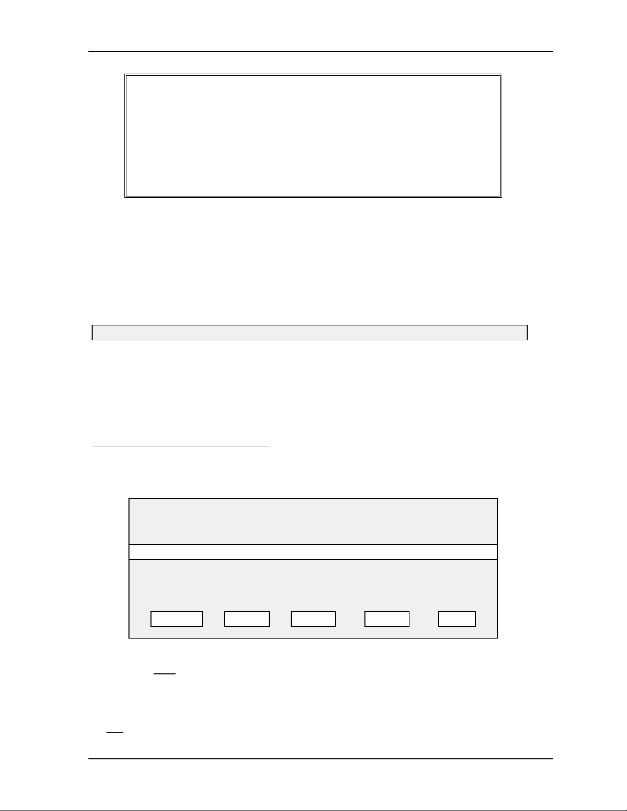
TAP100 Application Software Manual
TAP-100 VERSION X.XX I/O Assignments
DATE TIME page #
==========================================================
INPUT INPUTS OUTPUT OUTPUTS
LINKREADER 1234 PC READER 1 2
0 Reader 1 (01) N – – – PC Reader 2 (02) M –
1 Reader 2 (02) N – – – PC Reader 2 (02) M –
• • •
31 -----Available -----
After reviewing this information, if you are not satisfied with a link entry, you must use the up and
down arrow keys and select the link that needs changing. Once you have selected the link that
needs changing, you have two options: you can edit the existing link, making the necessary
corrections, or you can use your pointing device and select DISABLE, returning all inputs and
outputs to the factory default disabled settings.
Once you are satisfied that all I/O assignments are correct, you must send this information to all
control units on the network for it to take effect. Use your pointing device and select SEND. The
Status Message Line will display:
Initiating communication with local network on COM1 . . . please wait.
Once communication is established, the information is transferred to the network. Each reader
will beep twice, acknowledging they have received their data.
In this case, the result of these changes is that an input signal on the first input of either Reader 1
OR Reader 2 will create an output signal on the first output of reader 2.
Setting an ‘AND’ I/O Assignment
To set-up the required input to output links for an ‘AND’ connection, use your pointing device and
select Utilities and then I/O Assignments. Adding to the previous example for an ‘OR’ assignment,
the following prompt box will appear.
I/O ASSIGNMENTS
INPUT INPUTS OUTPUT OUTPUTS
LINKREADER 1234 PC READER 12
0 Reader 1 (01) N PC Reader 2 (02) M
1 Reader 2 (01) N PC Reader 2 (02) M
2 -----Available ----3 -----Available -----
• • •
MODIFY PRINT SEND CLEAR QUIT
In an ‘AND’ connection, you will use one I/O assignment link for all inputs to be ‘AND-ed’ together
(these inputs must reside on the same option board). All of these links will be assigned to the
same output on the same controller.
NOTE: To keep the hardware and software interface as simple as possible, and continue
to support both ‘OR’ and ‘AND’ logical functions, ‘AND-ing’ is limited to the inputs residing
on one controller.
Revision 3.3 Page 43
Page 44

TAP 100 Application Software Manual
Use the up and down arrows to select the links you wish to define. In this example, we will work
with I/O assignment link 3. We will use inputs 3 and 4 and we will use output 2 on reader 3.
Use the up and down arrows and place the highlight bar on link 3. Use your pointing device and
select MODIFY. The following prompt box will appear.
I/O ASSIGNMENTS FOR LINK 3
Input Reader: Sup I/O: No Polarity: Norm. Closed
Input Lines:
1
2
3
4
Output Reader:
Output Lines:
1
2
There are five fields you will need to work through to make the I/O assignment. If at any time
during the assignment process you wish to exit without making any changes, use your pointing
device and select QUIT. If at any time you wish to return all inputs and outputs to their factory
default values (all inputs and outputs disabled), use your pointing device and select DISABLE.
The first field to define is the Input Reader field. This field defines which reader the input signal is
coming from. Use your pointing device and select the Input Reader field. The following prompt
box will appear.
1 Reader 1
( ) Active ( ) Normal ( ) Tamper ( ) None
( ) Active ( ) Normal ( ) Tamper ( ) None
( ) Active ( ) Normal ( ) Tamper ( ) None
( ) Active ( ) Normal ( ) Tamper ( ) None
1 Reader 1
( ) Not Used ( ) Deactivate ( ) Activate ( ) Momentary
( ) Not Used ( ) Deactivate ( ) Activate ( ) Momentary
OK QUIT DISABLE
[ X ] Send to PC
Select A Reader
Choose an Input Reader
OK/ENTER accepts, QUIT/ESC cancels.
All
1 Reader 1
2 Reader 2
3 Reader 3
• • •
OK QUIT
To exit without selecting a reader, use your pointing device and select QUIT. For this example,
use your pointing device and select Reader 3, then select OK.
The second field to define is the Input Lines field. This field defines which of the 4 available inputs
at the reader is being assigned to this link. The factory default for all inputs is to set the input to
None. The input line can be defined in one of two ways: Active or Normal. A normal input is an
unsupervised 2-state input. An active input is a supervised 3- or 4-state input.
Page 44 Revision 3.3
Page 45

TAP100 Application Software Manual
NOTE: The Tamper value is used by the control unit itself. It is designed to be connected
to a tamper switch on the enclosure protecting the control unit. This allows you to define
an input to indicating if an individual is attempting to tamper with the control unit.
In this example, use your pointing device and select Normal on Input Lines 3 and 4. All other
inputs should be set to None.
The third field to define is the Output Reader field. This field defines which reader the output
signal is going to. Use your pointing device and select the Output Reader field.
Select A Reader
Choose an Output Reader
OK/ENTER accepts, QUIT/ESC cancels.
All
1 Reader 1
2 Reader 2
3 Reader 3
• • •
OK QUIT
To exit without selecting a reader, use your pointing device and select QUIT. For this example,
use your pointing device and select Reader 3, then select OK.
The fourth field defines if an event on the input should be recorded in the transactions log. Before
deciding, note that whenever an output is triggered (by an input signal) the output is always
reported in the transactions log. If you wish to have the redundancy of reporting the input that
triggered the output, as well as reporting the output, use your pointing device and select Send to
PC. For this example, we want to report input events, so use your pointing device and select
Send to PC.
The fifth field to define is the Output Lines field. This field defines which of the 2 available outputs
at the reader is being assigned to this link. The factory default for both outputs is set to Not Used.
The handling of the output line can be defined in one of three ways: Deactivate, Activate, or
Momentary. Deactivating the output sets the output relay to its inactive state. Activating the output
sets the output relay to its active state. Setting the output to Momentary will cause the output to
momentarily toggle its state. For this example, we want to toggle the output, so use your pointing
device and select Momentary for output 2.
After all of these changes have been made, the I/O Assignments for Link 3 prompt box should
appear as follows.
Revision 3.3 Page 45
Page 46

TAP 100 Application Software Manual
I/O ASSIGNMENTS FOR LINK 3
Input Reader: Sup I/O: No Polarity: Norm. Closed
Input Lines:
1
2
3
4
Output Reader:
Output Lines:
1
2
If all of the assignment information is correct, use your pointing device and select OK. The
TAP100 software will return to the I/O Assignments prompt box and display the following
information.
LINKREADER 1234 PC READER 12
0 Reader 1 (01) N PC Reader 2 (02) M
1 Reader 2 (02) N PC Reader 2 (02) M
2 -----Available ----3 Reader 3 (03) N PC Reader 2 (03) M
• • •
3 Reader 3
( ) Active ( ) Normal ( ) Tamper ( ) None
( ) Active ( ) Normal ( ) Tamper ( ) None
( ) Active ( ) Normal ( ) Tamper ( ) None
( ) Active ( ) Normal ( ) Tamper ( ) None
3 Reader 3
( ) Not Used ( ) Deactivate ( ) Activate ( ) Momentary
( ) Not Used ( ) Deactivate ( ) Activate ( ) Momentary
OK QUIT DISABLE
I/O ASSIGNMENTS
INPUT INPUTS OUTPUT OUTPUTS
[ X ] Send to PC
MODIFY
Once these I/O assignments have been made, you can PRINT them to review the entered
information. Follow the instructions provided on page 39 for the ‘OR’ I/O assignment section.
Once you have approved this information, you must SEND it to all control units on the network for
them to take affect. Follow the instructions provided on page 39 for the ‘OR’ I/O assignment
section.
PRINT SEND CLEAR QUIT
Clearing All I/O Assignments
If a major change needs to be made to the I/O assignment for the network, it may be easier to
clear the entire I/O assignment table and create a new one instead of editing the existing table.
To clear the entire I/O assignment table, use your pointing device and select Utilities and then I/O
Assignments. The following prompt box will appear.
This will clear all links in the I/O assignment list.
DO YOU REALLY
WANT TO DO THIS?
YES/OK
NO/CANCEL
Page 46 Revision 3.3
Page 47

TAP100 Application Software Manual
If you wish to clear all links and create a new I/O assignment table, use your pointing device and
select YES/OK. Otherwise select NO/CANCEL. Please use this command with care as it can
have a major impact on the security of your access control system.
Revision 3.3 Page 47
Page 48
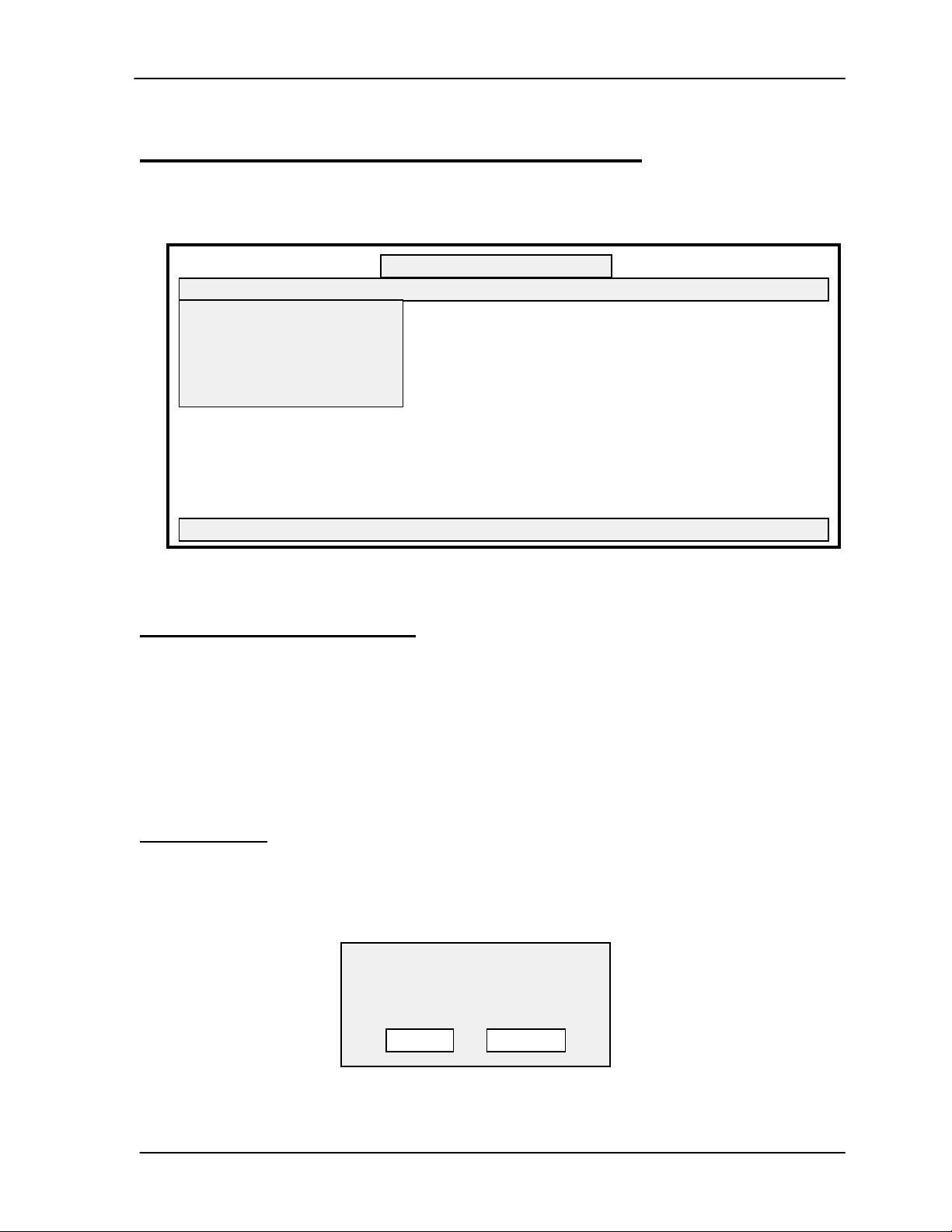
TAP 100 Application Software Manual
Creating/Maintaining a User Database
Once the TAP100 software, communications and the ProxNet have been configured, a user
database needs to be created and maintained. This section describes the process used to create
and maintain a user database: creating a cardfile and maintaining transaction data files.
TAP100 - Keri Systems, Inc.
Cards Transactions Readers Utilities Setup Info Quit
Open cardholder file
Enroll Batch of Cards
Get Network cards data
Get Memory Module data
Security Fence
Press a hot key to make a selection.
Figure 6 - Cards Menu Option Screen
Create a Cardfile Database
This section describes the commands used to enroll cards and create a cardfile, to search for
specific cardholder data, and to void cards from the system.
In the TAP100 software, cards are managed by enrolling them in a “slot.” A slot is a holding place
for information that applies to a specific card. Once cards are enrolled, information is entered
describing the person holding the card and the rights assigned to that person. This information
includes the slot’s identification number, the card’s unique number code, personnel information
regarding the person holding that card, and time zone information to be applied to that card.
Enrolling Cards
When enrolling cards, you can enroll a single card or a batch of cards. If you enroll a batch of
cards, they must be enrolled in consecutive slot numbers (i.e. 6 cards in slots 5 through 10). To
enroll cards in the system, use your pointing device and select Cards, and then Enroll Batch of
Cards. The following prompt box will appear.
BATCH ENROLL MODE
Start Slot No: ___
End Slot No: ___
OK
Page 48 Revision 3.3
QUIT
Page 49

TAP100 Application Software Manual
Use your pointing device and enter the starting slot and the ending slot. If you are not satisfied
with your entry, select QUIT to exit the selection without making a change. If your entry is correct,
use your pointing device and select OK.
For example: If you are entering one card into slot 5, the following prompt box will appear asking
you to confirm this entry.
You are about to enroll 1 cards at slots 5 to 5.
DO YOU REALLY
WANT TO DO THIS?
YES/OK
Or, if you are entering 6 cards into slots 5 through 10 the following prompt box will appear.
You are about to enroll 6 cards at slots 5 to 10.
DO YOU REALLY
WANT TO DO THIS?
YES/OK
If you are not ready to enter cards, use your pointing device and select NO/CANCEL. If you are
ready, select YES/OK. The following prompt box will appear.
BATCH ENROLL MODE
Opening channel to PROX.
The status message line will display:
Initiating communication with local network on COM1 . . . please wait.
NO/CANCEL
NO/CANCEL
Once communication is established, the following prompt box will appear.
BATCH ENROLL MODE
Now enrolling card at slot 5.
Present card to reader. . .
QUIT
One at a time, as prompted by the system, present the cards to be enrolled to the reader. As
each card is read and recognized by the reader, the reader will beep twice and briefly display the
following prompt box to indicate acceptance.
Revision 3.3 Page 49
Page 50
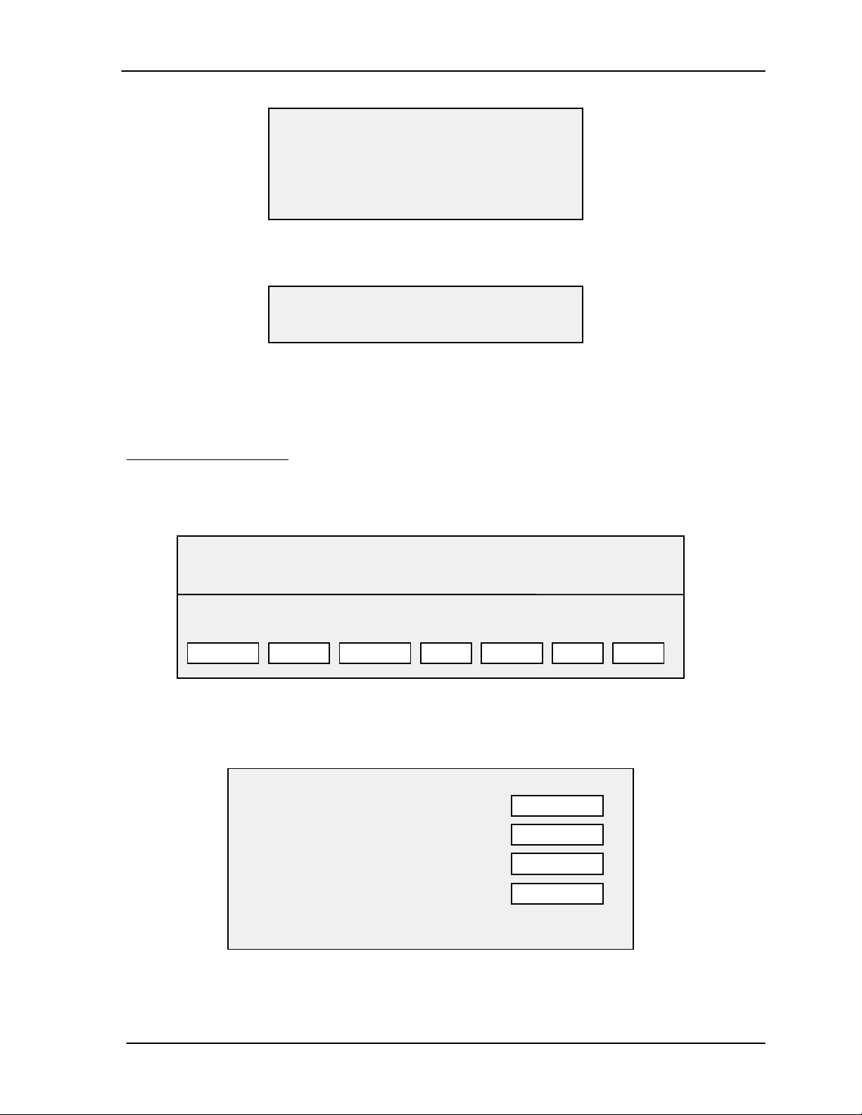
TAP 100 Application Software Manual
BATCH ENROLL MODE
Now enrolling card at slot 5.
Present card to reader. . .
Read card #0123456789 at slot 2.
Once all of the cards have been successfully read and all of the slots have been filled, the system
will display the following prompt box, indicating successful enrollment.
BATCH ENROLL MODE
Successfully enrolled slots 5 through 10.
NOTE: For ease of card/slot managment, you should consider marking each card with
the slot number you have assigned to it. This can make it easier for you to identify and
work with the cards within the system.
Open Cardholder File
The open cardholder file command opens the cards database, allowing you to enter or edit
specific information for each card user. Use your pointing device and select Cards, and then
Open cardholder file. The following prompt box will appear.
CARDS DATABASE: c:\proxnet\chf.dbf
TOTAL: xx cards enrolled LIMIT:none SORT: default
MOD SLOT FIRST LAST NAME DEPT HIRED
MODIFY BLOCK
Many options are available from this screen. The Modify command allows you to enter the user
specific data for that card’s slot. It can be used for initial cardfile database development, or for
changing values in an existing card slot. Use your pointing device and select Modify. The
following prompt box will appear.
Name:
Dept:
Hire Date:
ID:12345678 Card is Disabled [ ]
SEARCH
VOID PRINT SEND QUIT
Modify Slot 1
PERSONAL
ACCESS
OK
QUIT
This box will display the card’s ID number and the hire date of the person being assigned to their
card/slot combination (set at the current date). Initially, the name and department fields will be
Page 50 Revision 3.3
Page 51
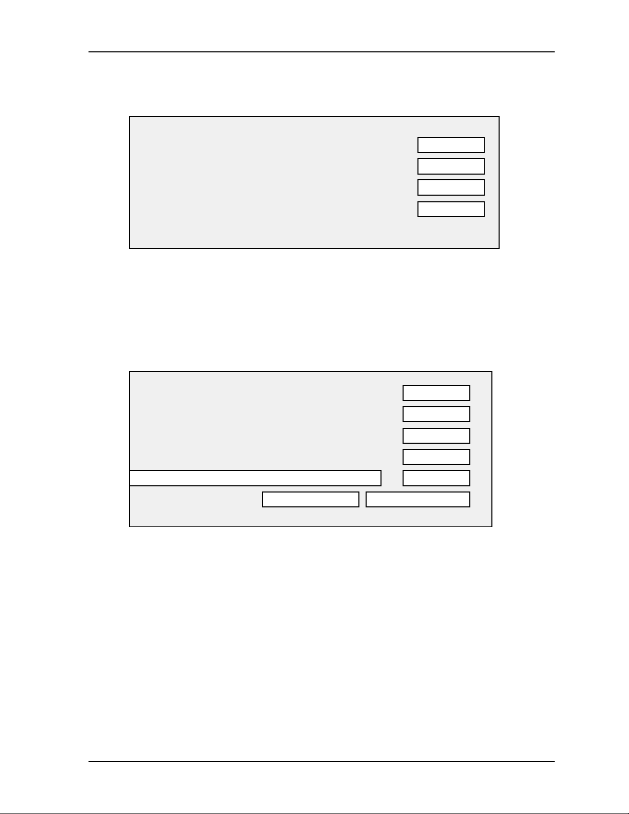
TAP100 Application Software Manual
blank and the disabled card field will be blank. To enter a card user’s name and department, use
your pointing device and select Personal. The prompt box will request the following information.
Modify Slot 1
Name:
Dept:
Hire Date:
ID:12345678 Card is Disabled [ ]
Use your pointing device and select the name field. Enter the card user’s first name, middle initial,
and last name. Use your pointing device and select the department field. Enter the card user’s
department (limited to four characters). If the hire date is not correct, use your pointing device and
enter the correct date in the hire date field.
Next you will enter the access rights information for the new card user. This access information is
the assignment of the time zones to be applied to the user’s card. Use your pointing device and
select Access. The prompt box will display the following information.
Access Rights for Slot 1
Cardholder Name: Joe Q Public
READER NAME TIME ZONE TZ# HOL
no name 1-A Always (00) HOL
no name 2-A Always (00) HOL
no name 3-A Always (00) HOL
EMP ENTRANCE Always (00) HOL
PERSONAL
ACCESS
OK
QUIT
MODIFY
BLOCK
PRINT
OK
QUIT
HOLIDAYS - ALL HOLIDAYS - NONE
You can enter time zone and holiday access information for that cardholder on a reader-byreader basis or in block mode, assigning the same time zone and holiday values to all readers.
To assign one time zone to the user’s card to be used by all readers, use your pointing device
and select Block. A listing of all time zones will be displayed. Use the arrow keys and arrow up or
down until the desired time zone is highlighted. If access on holidays is also to be granted, use
your pointing device and select Holiday Access.
Revision 3.3 Page 51
Page 52
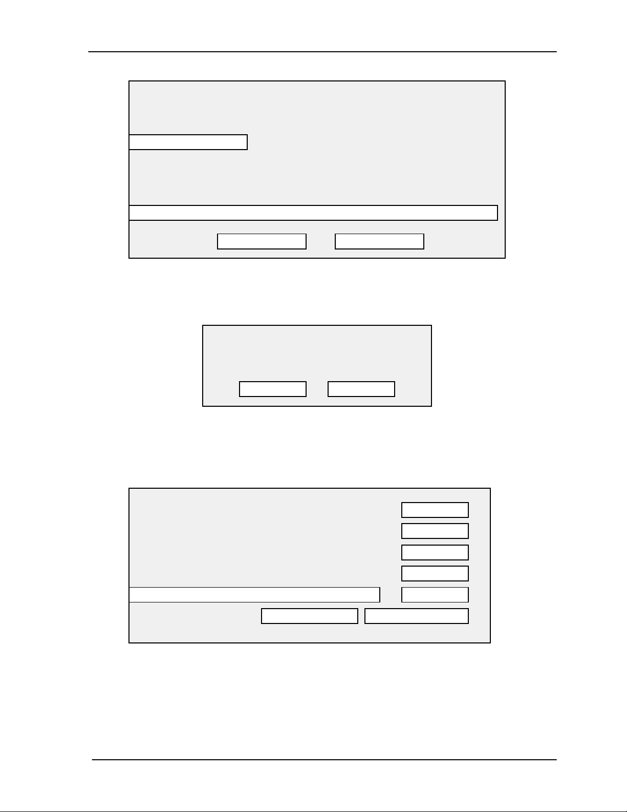
TAP 100 Application Software Manual
Access Authorization Selection
Choose a time zone to be applied to all readers.
[ ] Holiday Access
0Always
1 07:00 - 18:00 So Mo Tu We Th Fr Sa
2 15:00 - 00:30 So Mo Tu We Th Fr Sa
3 23:30 - 07:30 So Mo Tu We Th Fr Sa
4 07:00 - 16:00 So Mo Tu We Th Fr Sa
OK QUIT
If you are not satisfied with your entry, use your pointing device and select QUIT to exit the
selection without making a change. If your entry is correct, use your pointing device and select
OK. The following prompt box will appear asking you to confirm this entry.
All levels in this slot will be set to TZ 4 (hol)
DO YOU REALLY
WANT TO DO THIS?
YES/OK NO/CANCEL
If you are satisfied with your entry, use your pointing device and select YES/OK. Otherwise, use
your pointing device and select NO/CANCEL.
To assign time zone and holiday access information for a cardholder on a reader-by-reader basis,
use your pointing device and select Access. A listing of all readers will be displayed.
Access Rights for Slot 1
Cardholder Name:
READER NAME TIME ZONE TZ# HOL
no name 1-A Always (00) HOL
no name 2-A Always (00) HOL
no name 3-A Always (00) HOL
EMP ENTRANCE Always (00) HOL
HOLIDAYS - ALL HOLIDAYS - NONE
MODIFY
BLOCK
PRINT
OK
QUIT
Use the arrow keys and arrow up or down until the reader to be assigned time zone values is
highlighted. Use your pointing device and select Modify. A listing of all time zones will be
displayed.
Page 52 Revision 3.3
Page 53

TAP100 Application Software Manual
Access Authorization Selection
Choose a time zone to be applied to all readers.
[ ] Holiday Access
0Always
1 07:00 - 18:00 So Mo Tu We Th Fr Sa
2 15:00 - 00:30 So Mo Tu We Th Fr Sa
3 23:30 - 07:30 So Mo Tu We Th Fr Sa
4 07:00 - 16:00 So Mo Tu We Th Fr Sa
OK QUIT
Use the arrow keys and arrow up or down until the time zone to be assigned to the user’s slot for
that reader is highlighted. If access on holidays is also to be granted at that reader, use your
pointing device and select Holiday Access.
If you are satisfied with your entry, use your pointing device and select OK. Otherwise, use your
pointing device and select QUIT.
Once all slot/cardholder information has been entered, you can PRINT a hard copy of the
information just entered. This will allow you to review the slot/cardholder information one last time
before sending this information to the control units. To print a hard copy of the card database, use
your pointing device and select PRINT. The following prompt box will appear.
Print Job Progress
0% 100%
Press ESC to abort the print job.
As the slot/cardholder information is being printed, the status bar in this prompt box will monitor
how far along the print process is. When the print job has finished, you can review the
slot/cardholder information and verify it is correct. The printout will appear something like this.
TAP-100 VERSION X.XX Access Information for Slot X
DATE TIME page #
==========================================================
READER NAME TIME ZONE TZ# HOL
no name 1-A Never (07)
no name 2-A Never (07)
no name 3-A Never (07)
EMP ENTRANCE 07:00 - 16:00 Su Mo Tu We Th Fr Sa (04) HOL
no name 4-A Always (00) HOL
• • •
no name 32-A Never (00)
Revision 3.3 Page 53
Page 54

TAP 100 Application Software Manual
After reviewing this information, if you are not satisfied with your entry, use your pointing device
and select QUIT to exit without entering the information into the database. Otherwise, use your
pointing device and select OK. This will return you to the modify slot menu where you have one
more chance to review your information before making the entry into the cardholder database. If
you are satisfied with your entry, use your pointing device and select OK. This will return you to
the main cards database menu. Otherwise, use your pointing device and select QUIT.
Repeat this process for every card/slot/reader combination you wish to enter into the cardholder
database.
NOTE: As you make entries and changes in the card database, a ‘mod’ flag will appear to
the left of the new entry in the Cards database. This flag indicates the data has not yet
been sent to the network.
Once you have entered the information for every slot/user in the cardholder database, you must
send this information to all control units on the network for it to take effect. Use your pointing
device and select SEND. The following prompt box will be displayed.
Send Cards Data
Send data to:
Data to be sent:
To send data to the network, use your pointing device and select Network. You can choose to
send either data from All slots or data from Only modified slots.
NOTE: If the card file is large, or there are a large number of changes, selecting Only
modified slots will save transfer time as card information is sent to the network.
If you are not ready to send data to the network, use your pointing device and select QUIT.
Otherwise, use your pointing device and select OK. A new prompt box will appear, asking you to
verify your entry.
This will alter the cards information in the network.
[ ] Memory Module
[X] Network
[ ] All slots
[ •] Only modified slots
OK
DO YOU REALLY
WANT TO DO THIS?
QUIT
YES/OK NO/CANCEL
If you are satisfied with your entry, use your pointing device and select YES/OK. Or, select
NO/CANCEL to exit the selection without making a change.
The Status Message Line will display:
Initiating communication with local network on COM1 . . . please wait.
Page 54 Revision 3.3
Page 55
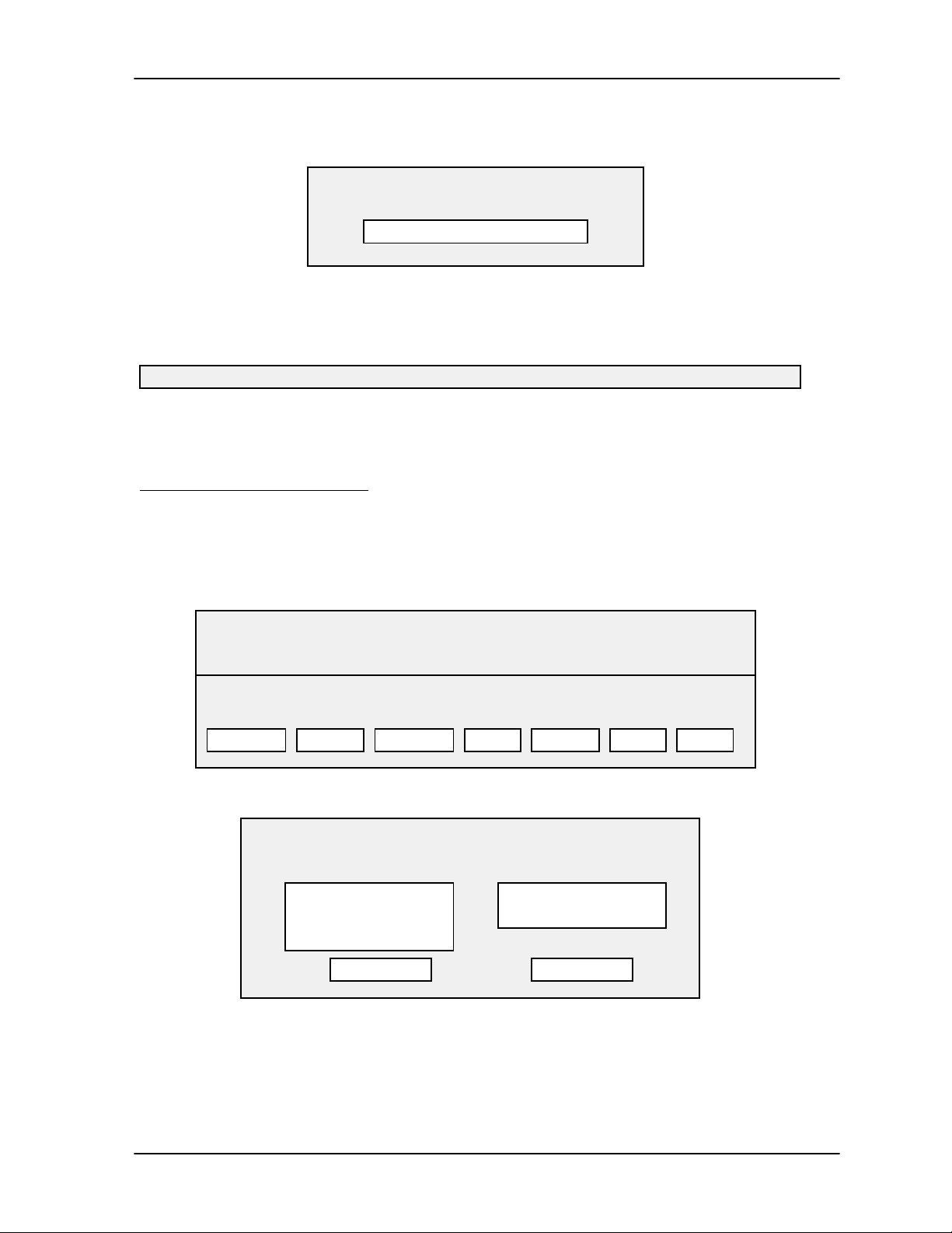
TAP100 Application Software Manual
Once communication is established, the information is transferred to the network.
Sending Cards to Network
0% 100%
As the slot/cardholder information is being sent to the network, the status bar in this prompt box
will monitor how far along the process is. When this process is complete, the Status Message
Line will display:
Successfully sent cards to network.
Once the cardholder file data is sent to the network, the cards data base construction process is
complete. Use your pointing device and select QUIT to return to the TAP100 main menu.
Search for Cardholder Data
The search for cardholder data command allows you to set search and sort criteria for cardholder
data. This allows you to define how you want to view the cardholder data, either by the card’s slot
number or by the name of the person assigned to a card/slot. To set a search/sort criteria, use
your pointing device and select Cards, and then Open cardholder file. The following prompt box
will appear.
CARDS DATABASE: c:\proxnet\chf.dbf
TOTAL: xx cards enrolled LIMIT:none SORT: default
MOD SLOT FIRST LAST NAME DEPT HIRED
MODIFY BLOCK
Use your pointing device and select SEARCH. The following prompt box will appear.
Limit viewing Sort Order
( • ) All cards
( ) Slot
( ) Name
The search criteria has three options allowing you to set the cardholder display screen to display
all cards assigned to slots in the cardholder database, all slots in the cardholder database, or all
names assigned to a card/slot in the database.
SEARCH
OK QUIT
VOID PRINT SEND QUIT
Search/Sort
( • ) By slot
( ) By name
Revision 3.3 Page 55
Page 56
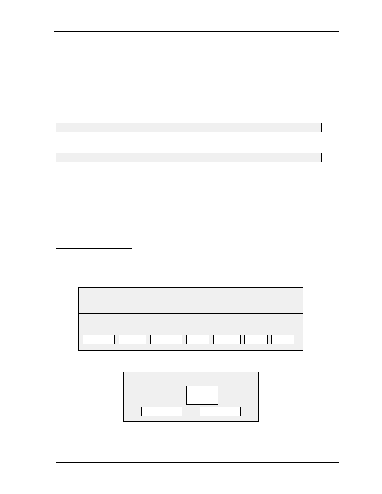
TAP 100 Application Software Manual
The sort criteria has two options allowing you to set the cardholder display screen to display all
slots in ascending numerical order or to display all slots by name in alphabetical order.
NOTE: Slots without an assigned user name have a lower alphabetical precedence than
those with an assigned user name. When sorting alphabetically, slots without an
assigned user name will be displayed before slots with an assigned user name.
Once you have determined the search/sort criteria needed to display the cardholder data you
need, use your pointing device and select the appropriate search/sort criteria. If you wish to exit
without making any search/sort criteria changes, select QUIT. If you are satisfied with your
entries, use your pointing device and select OK. The Status Message Line will display:
Constructing query data . . . please wait.
Once communication is established with the network, it will display:
Sorting query data . . . please wait.
Once the cardholder data has been searched and sorted to meet your requirements, it will be
displayed on the cardholder database screen.
Voiding Cards
Voiding cards removes them from the system’s list of slots with access rights. You can void one
card or a consecutive set of cards at one time. To void cards you do not have to have the card in
hand, but you must know the slot number issued to that card. If you do not know the card’s slot
number, but you do know information regarding the person holding that card, you can use the
Search for Cardholder Data command described on page 55 to find the required slot numbers to
void.
To void cards, use your pointing device and select Cards, and then Open cardholder file. The
following prompt box will appear.
CARDS DATABASE: c:\proxnet\chf.dbf
TOTAL: xx cards enrolled LIMIT:none SORT: default
MOD SLOT FIRST LAST NAME DEPT HIRED
MODIFY BLOCK
Use your pointing device and select Void. The following prompt box will appear.
SEARCH
VOID PRINT SEND QUIT
Void Cards
Start Slot #
End Slot#
OK QUIT
Use your pointing device and enter the starting slot and the ending slot. To void one card, the
starting slot and ending slot numbers are that one card’s slot number. If you are not satisfied with
Page 56 Revision 3.3
1
3
Page 57

TAP100 Application Software Manual
your entry, use your pointing device and select QUIT to exit the selection without making a
change. If your entry is correct, use your pointing device and select OK. The following prompt box
will appear.
You are about to void slots 1 to 3.
DO YOU REALLY
WANT TO DO THIS?
YES/OK
Since voiding cards removes them from the access control system, not allowing cardholders
access, the TAP100 software asks you to verify that the slot numbers you have entered are
indeed the ones to void. Review your entries and if they are not correct, you can exit the voiding
cards process by using your pointing device and selecting NO/CANCEL. Otherwise, use your
pointing device and select YES/OK. The following prompt box will appear.
This cannot be undone!!!
DO YOU REALLY
WANT TO DO THIS?
YES/OK
Since the voiding of cards cannot be undone requiring you to reenter all user information if a card
was voided incorrectly, the TAP100 software will prompt you one last time to verify that you do
indeed want to void these cards. This is your final opportunity to end the process without making
a change if you are not sure you want to void these cards. You can exit the voiding cards process
by using your pointing device and selecting NO/CANCEL. Otherwise, use your pointing device
and select YES/OK. The Status Message Line will display:
Initiating communication with local network on COM1 . . . please wait.
Once communication is established with the network, it will display:
NO/CANCEL
NO/CANCEL
Voiding slots ##.
And when all requested slots have been voided from the network, it will display:
Done.
Get Network Card Data
If the card log file has been lost or damaged, current card data can be restored from the readers
on the ProxLock network. This is done with the get network card data command. Use your
pointing device and select Cards and then Get Network cards data. The following prompt box will
appear.
Get cards will ERASE the current cards database.
DO YOU REALLY
WANT TO DO THIS?
YES/OK NO/CANCEL
Revision 3.3 Page 57
Page 58

TAP 100 Application Software Manual
If you do not want to erase the existing cards database, use your pointing device and select
NO/CANCEL. Otherwise, use your pointing device and select YES/OK. Since this operation
erases the existing cards database, a second prompt box will appear.
Just to be sure, I’ll ask you one more time:
DO YOU REALLY
WANT TO DO THIS?
YES/OK NO/CANCEL
If you do not want to erase the existing cards database, use your pointing device and select
NO/CANCEL. Otherwise, use your pointing device and select YES/OK. The status message line
will display:
Initiating communication with local network on COM1 . . . please wait.
Once communication has been established, the existing card database will be cleared and a new
database will be created as card data is collected from the readers on the ProxLock network.
Card data will be displayed in the following prompt box.
GET CARDS MONITORING
Initializing cards database . . . success.
#1 SLOT = 10
#2 SLOT = 11
#3 SLOT = 12
#4 SLOT = 13
Finished getting xx cards from network.
Press any key.
Collected card data is tabulated showing the cards collected by their slot number. Once all cards
have been retrieved, press any key to return to the TAP100 main menu.
Transaction Data File Management
The transaction file is a continuous log of every event that has occurred on the network. This data
is available for review, or for saving to a DOS file for use by a database program.
TAP100 - Keri Systems, Inc.
Cards Transactions Readers Utilities Setup Info Quit
Open transactions file
Get Network log data
Get Memory Module data
Monitor Events
Backup file
Press a hot key to make a selection.
Figure 7 - Transactions Menu Option Screen
Page 58 Revision 3.3
Page 59
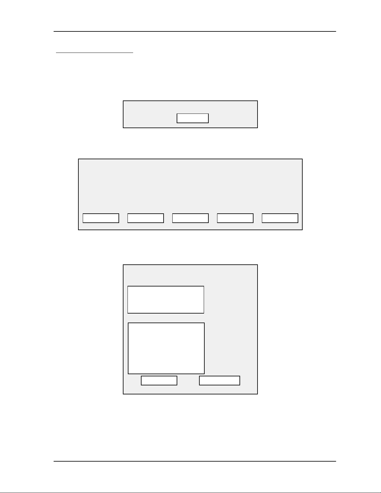
TAP100 Application Software Manual
Open Transactions File
The open transactions file command allows you to review a history of events that have occurred
on the network. It also allows you to get detailed information on any single event. To open the
transactions file, use your pointing device and select Transactions and then Open transactions
file. If no transactions have occurred (as in a brand new installation), the following prompt box will
appear.
The transaction database is empty.
OK
Otherwise, the following prompt box will appear (this prompt box displays sample transaction
data).
TRANSACTIONS LOG: c:\proxnet\log.dbf
TOTAL: XX events LIMIT: None SORT: Time & Date YEAR: 1996
DATE TIME SLOT CARDHOLDER READER DESCRIPTION
3/03 08:00 04 John Q Public 4-A EMP ENTR INP1-T/OPEN
3/03 17:00 04 John Q Public 4-B EMP EXIT OUT1-ACTIVE
• • •
SEARCH PRINT EXAMINE
From here, there are several options available for viewing transaction log data. If you need to
search for specific information, you can set sort and transaction file viewing criteria. Use your
pointing device and select SEARCH. The following prompt box will appear.
Search/Sort
Sort Order
( • ) By Date and Time
( ) By Slot
( ) By Name
Limit Viewing
[ ] Slot
[ ] Name
[ ] Reader
[ ] Date
[ ] Time
[ ] Type
OK QUIT
OPTIONS
QUIT
Depending upon how you wish to view the transaction data, use your pointing device and select a
sort order. You can sort transaction data based on the date and time of events, the card/slot that
initiated events or the names of the cardholders that initiated events.
If this sort order provides too much data for viewing, you can limit the transaction data further.
Use your pointing device and select one of the limit viewing options.
Revision 3.3 Page 59
Page 60

TAP 100 Application Software Manual
If you select Slot, the following prompt box appears.
Slot Range
Start:
End:
Press ENTER key if data is OK.
Press ESC key to quit.
The default is all available slots. Use your pointing device and select the range of slots you wish
to limit viewing to. Press
to not set a slot range.
If you select Name, the following prompt box appears.
The default is the entire alphabet. Use your pointing device and select the range of letters you
wish to limit viewing to. Press
<ESC>
to not set a name range.
<ENTER>
Start:
End:
Press ENTER key if data is OK.
Press ESC key to quit.
0
7000
if the slot range entered is correct. Otherwise , press
Name Range
A
Z
<ENTER>
if the name range entered is correct. Otherwise , press
<ESC>
If you select Reader, the following prompt box appears.
Reader Range
Start:
End:
Press ENTER key if data is OK.
Press ESC key to quit.
The default is all available readers. Use your pointing device and select the range of readers you
wish to limit viewing to. Press
<ESC>
If you select Date, the following prompt box appears.
to not set a reader range.
Start:
End:
Press ENTER key if data is OK.
Press ESC key to quit.
1
32
<ENTER>
01/01/1900
12/31/9999
if the reader range entered is correct. Otherwise , press
Date Range
Page 60 Revision 3.3
Page 61

TAP100 Application Software Manual
The default is a large date range. Use your pointing device and select the date range you wish to
limit viewing to. Press
not set a date range.
If you select Time, the following prompt box appears.
<ENTER>
if the date range entered is correct. Otherwise , press
Time Range
<ESC>
to
Start:
End:
Press ENTER key if data is OK.
Press ESC key to quit.
The default is the full 24-hour clock. Use your pointing device and select the time range you wish
to limit viewing to. Press
to not set a time range.
If you select Type, the following prompt box appears.
The default is to display cards. Use your pointing device and select cards only to view all card
related transactions, alarms only to view all alarm related transactions, and intercom only to view
all communication related transactions. Press
type. Otherwise , press
<ENTER>
Press ENTER key if data is OK.
Press ESC key to quit.
<ESC>
00:00
23:59
if the time range entered is correct. Otherwise , press
Select Type
( ) 1 - Cards only
( ) 2 - Alarms only
( ) 3 - Intercom only
<ENTER>
to not set a transaction type.
once you have selected a transaction
<ESC>
If you do not wish to select specific sort criteria, use your pointing device and select QUIT.
Otherwise, use your pointing device and select OK. The original transactions log prompt box will
appear with all transaction data sorted according to the criteria you have set.
TRANSACTIONS LOG: c:\proxnet\log.dbf
TOTAL: XX events LIMIT: None SORT: Time & Date YEAR: 1996
DATE TIME SLOT CARDHOLDER READER DESCRIPTION
3/03 08:00 04 John Q Public 4-A EMP ENTR INP1-T/OPEN
3/03 17:00 04 John Q Public 4-B EMP EXIT OUT1-ACTIVE
• • •
SEARCH
If you wish to have hard copy of this data, you can print it out. Use your pointing device and select
PRINT. The following prompt box will appear.
Revision 3.3 Page 61
PRINT EXAMINE OPTIONS
QUIT
Page 62

TAP 100 Application Software Manual
Print Job Progress
0% 100%
Press ESC to abort the print job.
As transaction information is being printed, the status bar in this prompt box will monitor how far
along the print process is. When the print job has finished, you can review the transaction data.
The printout will appear something like this.
TAP-100 VERSION X.XX Transaction Log
DATE TIME page #
==========================================================
DATE TIME SLOT CARDHOLDER READER DESCRIPTION
3/03 08:00 04 John Q Public 4-A EMP ENTR INP1-T/OPEN
3/03 17:00 04 John Q Public 4-B EMP EXIT OUT1-ACTIVE
• • •
If you wish, you can examine one specific transaction without the clutter of all other transactions.
Use the up and down arrows and select the specific transaction you wish to examine. Then use
your pointing device and select EXAMINE. The following prompt box will appear.
Examining Transaction
DATE: 12/20
TIME: 9:33
SLOT: 04
CARDHOLDER: John Q Public
READER: EMP ENTRANCE
DESCRIPTION: MANAGER
OK
Once you have finished examining this transaction, use your pointing device and select OK.
To limit the information that is displayed on the screen, you can set transaction viewing options.
Use your pointing device and select OPTIONS. The following prompt box will appear.
Event Log Viewing Options
( ) Show Slot Numbers and Cardholder Names
( ) Show Cardholder Names Only
( ) Show Reader Numbers and Names
( ) Show Names of Readers Only
OK QUIT
Page 62 Revision 3.3
Page 63

TAP100 Application Software Manual
If you do not wish to set event log viewing options, use your pointing device and select QUIT.
Otherwise, use your pointing device and select the event log viewing option that will best display
transaction data for your monitoring purposes. Then use your pointing device and select OK.
The original transactions log prompt box will appear with all transaction data screened according
to the criteria you have set. With the screening criteria set above, transaction data would be
displayed as follows.
TRANSACTIONS LOG: c:\proxnet\log.dbf
TOTAL: XX events LIMIT: None SORT: Time & Date YEAR: 1996
DATE TIME CARDHOLDER READER DESCRIPTION
3/03 08:00 John Q Public 4-A EMP ENTR INP1-T/OPEN
3/03 17:00 John Q Public 4-B EMP EXIT OUT1-ACTIVE
• • •
SEARCH
Once you have finished viewing the transactions log data, use your pointing device and select
QUIT to return to the TAP100 main menu.
PRINT EXAMINE OPTIONS
QUIT
Archiving a Transaction Log
For efficient data storage purposes, we recommend you periodically archive the transaction log.
This can allow you to maintain a set of unique transaction files for time periods that you can refer
to at a later date. For example, you could archive the transaction log once a month, naming the
archive file in a manner that identifies the time-period being archived (i.e. jan96.dbf and jan96.cdx
for the transaction log for the month of January, 1996).
To archive a transaction log, you will have to exit the TAP100 software and execute a series of
DOS commands.
From the TAP100 main menu, use your pointing device and select QUIT and then select YES/OK
to exit the program. Following the example above, at the DOS prompt type:
C:\PROXNET>
After a short delay, the DOS prompt will return. Type:
C:\PROXNET>
These DOS commands save the contents of the entire transaction log into two DOS files.
To restart the TAP100 software, at the DOS prompt type:
C:\PROXNET>
ren log.dbf jan96.dbf <ENTER>
ren log.cdx jan96.cdx <ENTER>
tap100 <ENTER>
When the TAP100 software starts, the default transaction files will be empty, ready for a new set
of transaction data.
Revision 3.3 Page 63
Page 64

TAP 100 Application Software Manual
Backup File
The backup file command allows you to review the data in an archived transaction log file. Use
your pointing device and select Transactions and then Backup file. The following prompt box will
appear.
Enter backup filename:
Enter the name of an existing transaction data file and press
example above). The TAP100 software will display the transaction log file data and allow you to
view and manipulate the data as in the Open Transactions File command beginning on page 59.
<ENTER>
(i.e. jan96.dbf as in the
Get Network Transaction Data
If the transaction log file has been lost or damaged, current transaction data can be restored from
the readers on the ProxLock network. This is done with the get network transaction data
command. Use your pointing device and select Transactions and then Get Network log data. The
following prompt box will appear.
Do you want to clear the readers’ transactions
logs after getting transactions from them?
YES NO QUIT
If you want to exit this command without retrieving the readers’ transaction logs, use your pointing
device and select QUIT.
If you want to clear the readers’ memories as you retrieve the readers’ transaction logs, use your
pointing device and select YES. The status message line will display:
Initiating communication with local network on COM1 . . . please wait.
Once communication has been established with the local network, the status message line will
count off the readers communicated with and the number of transactions collected.
Have xx of xx events from reader yy; grand total of zz.
The status message line will keep a running total until all readers and transactions have been
retrieved.
Done with all readers. Total zz transactions fetched.
When this process is complete, the following prompt box will appear.
Page 64 Revision 3.3
Page 65

TAP100 Application Software Manual
GETTING TRANSACTIONS FROM NETWORK
DATE TIME CARDHOLDER READER DESCRIPTION
3/03 08:00 John Q Public 4-A EMP ENTR INP1-T/OPEN
3/03 17:00 John Q Public 4-B EMP EXIT OUT1-ACTIVE
• • •
Clearing xx transactions from reader yy.
Press any key to continue.
Press any key to return to the TAP100 main menu. All reader/network transactions have been
retrieved and can be viewed and manipulated using the Open Transactions File command on
page 59 or archived using the Backup File command on page 64. All transaction data has been
cleared from the readers.
If you want to retrieve the readers’ transaction logs but do not want to clear these logs (allowing
the readers to continue to add transaction information to them), use your pointing device and
select NO. The status message line will display:
Initiating communication with local network on COM1 . . . please wait.
Once communication has been established with the local network, the status message line will
count off the readers communicated with and the number of transactions collected.
Have xx of xx events from reader yy; grand total of zz.
The status message line will keep a running total until all readers and transactions have been
retrieved.
Done with all readers. Total zz transactions fetched.
When this process is complete, the following prompt box will appear.
GETTING TRANSACTIONS FROM NETWORK
DATE TIME CARDHOLDER READER DESCRIPTION
3/03 08:00 John Q Public 4-A EMP ENTR INP1-T/OPEN
3/03 17:00 John Q Public 4-B EMP EXIT OUT1-ACTIVE
• • •
Press any key to continue.
Press any key to return to the TAP100 main menu. All reader/network transactions have been
retrieved and can be viewed and manipulated using the Open Transactions File command on
page 59 or archived using the Backup File command on page 64. All transaction data remains on
the readers and will continue to be added to as events occur on the network.
Revision 3.3 Page 65
Page 66

TAP 100 Application Software Manual
Advanced Commands
Advanced commands are used to perform specific immediate tasks on the network. These tasks
include real-time monitoring of network events, installing a new reader to an existing network,
immediate reader locking and unlocking, global locking and unlocking of all readers, and card
security functions.
Monitor Network Events
The monitor network events command allows you to monitor the network communication line and
review in real-time events that are occurring at the readers and alarm relays. To monitor network
events, use your pointing device and select Transactions, and then Monitor Events. The Status
Message Line will display:
Initiating communication with local network on COM1 . . . please wait.
Once communication is established with the network, the Status Message Line will display:
Monitoring events.
And the following prompt box will appear.
MONITORING EVENTS ON NETWORK
DATE TIME CARDHOLDER READER DESCRIPTION
QUIT
As events such as access, egress, or alarm conditions occur on the network, a status line
announcing the event will appear on the screen. When you no longer need to monitor network
events, use your pointing device and select OK. The prompt box will note on the screen:
MONITORING EVENTS ON NETWORK
DATE TIME CARDHOLDER READER DESCRIPTION
******** REQUEST TO END MONITOR MODE ********
QUIT
And the Status Message Line will display:
MONITOR MODE WILL END IN 20 SECONDS.
The software clock will count down from 20 seconds and then return to the TAP100 main menu.
The system will continue to post events until the clock ends its count.
Page 66 Revision 3.3
Page 67

TAP100 Application Software Manual
Install New Reader
The install new reader command sends all the required TAP100 software operating/configuration
information to a reader that has been added to the access control network. It may also be used to
re-initialize a reader that has had its EPROM firmware updated or is no longer responding to the
access control network.
NOTE: When used to re-initialize a reader that has had its EPROM firmware updated or
is no longer responding to the access control network, the install new reader command
must be used with caution because it clears out all events stored locally for that reader.
To install a new reader, use your pointing device and select Readers and then Install new reader.
The following prompt box will appear.
Reader number to install: (1-32)
Communication will begin with the selected reader and the Status Message Line will display:
Initiating communication with local network on COM1 . . . please wait.
Once communication has been established, the Status Message Line will then change to reflect
each new block of information being sent to the new reader. When complete, the display
automatically returns to the main menu screen.
NOTE: After installing a new reader, we recommend executing the Verify Network
command on page 23 and the Query Status of a Reader command on page 37 to verify
the reader installation has been recognized by the ProxNet system.
Once the new reader has been added, the reader should be configured in the ProxNet system
(see the Configure the Readers section beginning on page 33). The card database should also
be modified to apply the new reader’s access control information to user’s cards (see the Open
Cardholder File command beginning on page 50).
Lock/Unlock Commands
There are two types of lock/unlock commands. The first type performs an immediate lock or
unlock of a door connected to one reader. The second type enables or disables the automatic
locking or unlocking all readers on the network at one time.
Lock A Reader
The lock a reader command immediately locks a selected reader, preventing access or egress.
To immediately lock a reader, use your pointing device and select Readers and then Lock a
reader. The following prompt box will appear.
Reader number to lock: (1-32)
The Status Message Line will display:
Initiating communication with local network on COM1 . . . please wait.
Revision 3.3 Page 67
Page 68

TAP 100 Application Software Manual
Once communication is complete, the reader is locked.
Unlock A Reader
The unlock a reader command immediately unlocks a selected reader, allowing access or egress.
To immediately unlock a reader, use your pointing device and select Readers and then Unlock a
reader. The following prompt box will appear.
Reader number to unlock: (1-32)
The Status Message Line will display:
Initiating communication with local network on COM1 . . . please wait.
Once communication is complete, the reader is unlocked.
Enable Global Lock/Unlock
The enable global lock/unlock (GLU) function allows an external device to automatically lock or
unlock all readers on the network at one time. The factory default value is to disable this feature,
so you must enable the global lock/unlock feature if you want to use it.
When enabled, the master control unit will monitor the input state of the External Time Zone input
relay, also known as AUX IP0 (TB1, pins 1 and 2). The default sense of the GLU input is TTL
Logic 0, corresponding to a global lock readers command. TTL Logic 1 at the GLU input
corresponding to a global unlock readers command. All other system functions continue to
operate as usual, including the automatic lock/unlock (ALU) time functions.
While enabled and the GLU input is in the locked state, all doors on the network will remain
locked until one of three possible conditions are detected.
1. A change in the GLU input state from 0 to 1 is received.
2. An unlock a reader command is received.
3. An ALU time is met.
When one of these conditions is achieved, the appropriate doors will be unlocked.
While enabled and the GLU input is in the unlocked state, all doors on the network will remain
unlocked until a change in the GLU input from 1 to 0 is received. When this condition is achieved,
all doors will be locked without exception. The GLU lock command takes precedence over all
other functions including the ALU function.
Enabling the GLU feature will immediately lock all doors if the GLU input is at the appropriate
state.
Regardless of if the GLU command is enabled or disabled, every state change at the GLU input is
logged and forwarded to the host.
To enable the global lock/unlock function, use your pointing device and select Readers and then
Enable global lock/unlock. The Status Message Line will display:
Initiating communication with local network on COM1 . . . please wait.
Page 68 Revision 3.3
Page 69

TAP100 Application Software Manual
Once communication is complete, the global lock/unlock function has been enabled.
Disable Global Lock/Unlock
The disable global lock/unlock (GLU) function disables the ability for an external device to
automatically lock or unlock all readers on the network at one time.
Disabling the GLU feature from the enabled state while a global unlock is in force will immediately
lock all doors and then restore the doors to the appropriate automatic lock/unlock (ALU) state
(see Table 2 to determine the appropriate ALU state).
Regardless of if the GLU command is enabled or disabled, every state change at the GLU input is
logged and forwarded to the host.
To disable the global lock/unlock function, use your pointing device and select Readers and then
Disable global lock/unlock. The Status Message Line will display:
Initiating communication with local network on COM1 . . . please wait.
Once communication is complete, the global lock/unlock function has been disabled.
Table 2 - Automatic Lock/Unlock State
ALU STATE LOCK STATE EVENT PXL-100 ACTION STATE
CHANGES
Lock Command no action
LOCKED Unlock Command unlock door SUSPEND,
UNLOCKED
Global Secure Time no action
ON
Lock Command lock door SUSPEND,
LOCKED
UNLOCKED Unlock Command no action
Global Secure Time no action
Lock Command no action
LOCKED Unlock Command unlock door
Global Secure Time no action
OFF
Lock Command lock door
UNLOCKED Unlock Command no action
Global Secure Time lock door
Lock Command no action
LOCKED Unlock Command unlock door ON, UNLOCKED
Global Secure Time ON
SUSPEND
Lock Command lock door ON, LOCKED
UNLOCKED Unlock Command no action
Global Secure Time ON
Revision 3.3 Page 69
Page 70

TAP 100 Application Software Manual
Card Security Management Commands
There are two system security management commands. The first, anti-passback amnesty, clears
the anti-passback counter allowing “reaccess” for cards. The second, the card security fence,
allows cards to remotely arm an alarm panel.
Anti-Passback Amnesty
The anti-passback command is used to ensure one-card/one-way access into and then out of a
controlled area. An authorized card presented to the access reader will allow access, but will not
work again for access until one of three things happens: the card has been used to exit through
an egress reader, 24 hours have passed, or the access control system has been reset by the
Anti-passback amnesty command. This command resets the passback status flag for all cards in
the system, allowing a card previously considered inside the access area to be reused for access.
To grant anti-passback amnesty, use your pointing device and select Utility, and then APB
Amnesty. The Status Message Line will display:
Initiating communication with local network on COM1 . . . please wait.
Once communication is complete, anti-passback amnesty has been granted.
Set the Card Security Fence
The card security fence command allows cards to be used to remotely arm or disarm an alarm
panel. To set the security fence, a slot number is designated to be a boundary between
“privilegded” and “non-privileged” cards. Cards at or below this slot number become privilidged
cards, cards that are above this slot number become non-privilgeded cards. When a priviliged
card is presented to a reader, the reader’s alarm panel becomes armed. Non-priviliged cards can
still be granted access, but will cause an alarm event if the alarm panel has been armed. The
factory default slot number is 0, disabling this command. For hardware implementation
information, please refer to the OB-3 Input/Output and Alarm Panel Control option board manual.
To set the security fence, determine the slot number at which you wish to make the priviliged/nonpriviliged division.
For example: To set the security fence to slot 100, use your pointing device and select Cards and
then Security Fence. The following prompt box will appear.
Security Fence
Enter slot number:
Type:
0 1 0 0 <ENTER>
The Status Message Line will display:
Initiating communication with local network on COM1 . . . please wait.
Once communication is established, the Status Message Line will display:
Page 70 Revision 3.3
Page 71

Security Fence set to 100. Nodelist = 00000001.
The security fence has now been set.
TAP100 Application Software Manual
Revision 3.3 Page 71
Page 72

TAP 100 Application Software Manual
This page is intentionally left blank.
Page 72 Revision 3.3
Page 73

Appendices
1. Status of Doors Table
2. Responding Nodes Table
3. Time Zone Table Worksheet
4. Glossary of Terms
5. Customer Support Information
6. Warranty Information
TAP100 Application Software Manual
Revision 3.3 Page 73
Page 74

TAP 100 Application Software Manual
This page is intentionally left blank.
Page 74 Revision 3.3
Page 75

TAP100 Application Software Manual
Status of Doors Table
The status of doors table is provided to help you determine which doors are secured. Execute the
Verifying Network Operation command found on page 23 and compare the status of doors value
returned to the entries in this table.
Hexadecimal Digit Hexadecimal Value Binary Value Active Readers
xxxx xxx
X
if X is a . . .
0 0000 4, 3, 2, and 1
1 0001 4, 3, and 2
2 0010 4, 3, and 1
3 0011 4 and 3
4 0100 4, 2, and 1
5 0101 4 and 2
6 0110 4 and 1
7 0111 4
8 1000 3, 2, and 1
9 1001 3 and 2
A 1010 3 and 1
B 1011 3
C 1100 2 and 1
D 1101 2
E 1110 1
F 1111
its value is . . . indicating the secured doors are . . .
doors 4, 3, 2, and 1 are
not secured
xxxx xxXxif
is a . . .
X
0 0000 8, 7, 6, and 5
1 0001 8, 7, and 6
2 0010 8, 7, and 5
3 0011 8 and 7
4 0100 8, 6, and 5
5 0101 8 and 6
6 0110 8 and 5
7 0111 8
8 1000 7, 6, and 5
9 1001 7 and 6
A 1010 7 and 5
B 1011 7
C 1100 6 and 5
D 1101 6
E 1110 5
F 1111
its value is . . . indicating the secured doors are . . .
doors 8, 7, 6, and 5 are
not secured
Revision 3.3 Page 75
Page 76

TAP 100 Application Software Manual
Status of Doors Table (continued)
Hexadecimal Digit Hexadecimal Value Binary Value Active Readers
xxxx xXxx if X is a . . .
0 0000 12, 11, 10, and 9
1 0001 12, 11, 10
2 0010 12, 11, and 9
3 0011 12 and 11
4 0100 12, 10, and 9
5 0101 12 and 10
6 0110 12 and 9
7 0111 12
8 1000 11, 10, and 9
9 1001 11 and 10
A 1010 11 and 9
B 1011 11
C 1100 10 and 9
D 1101 10
E 1110 9
F 1111
its value is . . . indicating the secured doors are . . .
12, 11, 10, and 9 are
not secured
xxxx Xxxx if X is a . . .
0 0000 16, 15, 14, and 13
1 0001 16, 15, and 14
2 0010 16, 15, and 13
3 0011 16 and 15
4 0100 16, 14, and 13
5 0101 16 and 14
6 0110 16 and 13
7 0111 16
8 1000 15, 14, and 13
9 1001 15 and 14
A 1010 15 and 13
B 1011 15
C 1100 14 and 13
D 1101 14
E 1110 13
F 1111
xxxX xxxx if X is a . . .
0 0000 20, 19, 18, and 17
1 0001 20, 19, and 18
2 0010 20, 19, and 17
3 0011 20 and 19
4 0100 20, 18, and 17
5 0101 20 and 18
6 0110 20 and 17
7 0111 20
8 1000 19, 18, and 17
9 1001 19 and 18
A 1010 19 and 17
B 1011 19
C 1100 18 and 17
D 1101 18
E 1110 17
F 1111
its value is . . . indicating the secured doors are . . .
doors 16, 15, 14, and 13 are
its value is . . . indicating the secured doors are . . .
doors 20, 19, 18, and 17 are
not secured
not secured
Page 76 Revision 3.3
Page 77

TAP100 Application Software Manual
Status of Doors Table (continued)
Hexadecimal Digit Hexadecimal Value Binary Value Active Readers
xxXx xxxx if X is a . . .
0 0000 24, 23, 22, and 21
1 0001 24, 23, and 22
2 0010 24, 23, and 21
3 0011 24 and 23
4 0100 23, 22, and 21
5 0101 24 and 22
6 0110 24 and 21
7 0111 24
8 1000 23, 22, and 21
9 1001 23 and 22
A 1010 23 and 21
B 1011 23
C 1100 22 and 21
D 1101 22
E 1110 21
F 1111
its value is . . . indicating the secired doors are . . .
doors 24, 23, 22, and 21 are
not secured
xXxx xxxx if X is a . . .
0 0000 28, 27, 26, and 25
1 0001 28, 27, and 26
2 0010 28, 27, and 25
3 0011 28 and 27
4 0100 28, 26, and 25
5 0101 28 and 26
6 0110 28 and 25
7 0111 28
8 1000 27, 26, and 25
9 1001 27 and 26
A 1010 27 and 25
B 1011 27
C 1100 26 and 25
D 1101 26
E 1110 25
F 1111
xxx xxxx if X is a . . .
X
0 0000 32, 31, 30, 29
1 0001 32, 31, and 30
2 0010 32, 31, and 29
3 0011 32 and 31
4 0100 32, 30, and 29
5 0101 32 and 30
6 0110 32 and 29
7 0111 32
8 1000 31, 30, and 29
9 1001 31 and 30
A 1010 31 and 29
B 1011 31
C 1100 30 and 29
D 1101 30
E 1110 29
F 1111
its value is . . . indicating the secured doors are . . .
doors 28, 27, 26, and 25 are
its value is . . . indicating the secured doors are . . .
doors 32, 31, 30, and 29 are
not secured
not secured
Revision 3.3 Page 77
Page 78

TAP 100 Application Software Manual
Responding Nodes Table
The responding nodes table is provided to help you determine which nodes are active and
responding to the network. Execute the Verifying Network Operation command found on page 23
and compare the responding nodes value returned to the entries in this table.
Hexadecimal Digit Hexadecimal Value Binary Value Active Readers
xxxx xxx
X
if X is a . . .
0 0000
1 0001 1
2 0010 2
3 0011 2 and 1
4 0100 3
5 0101 3 and 1
6 0110 3 and 2
7 0111 3, 2, and 1
8 1000 4
9 1001 4 and 1
A 1010 4 and 2
B 1011 4, 2, and 1
C 1100 4 and 3
D 1101 4, 3, and 1
E 1110 4, 3, and 2
F 1111 4, 3, 2, and 1
its value is . . . indicating the active readers are . . .
4, 3, 2, and 1 are
inactive
xxxx xxXxif
is a . . .
X
0 0000
1 0001 5
2 0010 6
3 0011 6 and 5
4 0100 7
5 0101 7 and 5
6 0110 7 and 6
7 0111 7, 6, and 5
8 1000 8
9 1001 8 and 5
A 1010 8 and 6
B 1011 8, 6, and 5
C 1100 8 and 7
D 1101 8, 7, and 5
E 1110 8, 7, and 6
F 1111 8, 7, 6, and 5
its value is . . . indicating the active readers are . . .
8, 7, 6, and 5 are
inactive
Page 78 Revision 3.3
Page 79

TAP100 Application Software Manual
Responding Nodes Table (continued)
Hexadecimal Digit Hexadecimal Value Binary Value Active Readers
xxxx xXxx if X is a . . .
0 0000
1 0001 9
2 0010 10
3 0011 10 and 9
4 0100 11
5 0101 11 and 9
6 0110 11 and 10
7 0111 11, 10, and 9
8 1000 12
9 1001 12 and 9
A 1010 12 and 10
B 1011 12, 10, and 9
C 1100 12 and 11
D 1101 12, 11, and 9
E 1110 12, 11, and 10
F 1111 12, 11, 10, and 9
its value is . . . indicating the active readers are . . .
12, 11, 10, and 9 are
inactive
xxxx Xxxx if X is a . . .
0 0000
1 0001 13
2 0010 14
3 0011 14 and 13
4 0100 15
5 0101 15 and 13
6 0110 15 and 14
7 0111 15, 14, and 13
8 1000 16
9 1001 16 and 13
A 1010 16 and 14
B 1011 16, 14, and 13
C 1100 16 and 15
D 1101 16, 15, and 13
E 1110 16, 15, and 14
F 1111 16, 15, 14, and 13
xxxX xxxx if X is a . . .
0 0000
1 0001 17
2 0010 18
3 0011 18 and 17
4 0100 19
5 0101 19 and 17
6 0110 19 and 18
7 0111 19, 18, and 17
8 1000 20
9 1001 20 and 17
A 1010 20 and 18
B 1011 20, 18, and 17
C 1100 20 and 19
D 1101 20, 19, and 17
E 1110 20, 19, and 18
F 1111 20, 19, 18, and 17
its value is . . . indicating the active readers are . . .
16, 15, 14, and 13 are
its value is . . . indicating the active readers are . . .
20, 19, 18, and 17 are
inactive
inactive
Revision 3.3 Page 79
Page 80

TAP 100 Application Software Manual
Responding Nodes Table (continued)
Hexadecimal Digit Hexadecimal Value Binary Value Active Readers
xxXx xxxx if X is a . . .
0 0000
1 0001 21
2 0010 22
3 0011 22 and 21
4 0100 23
5 0101 23 and 21
6 0110 23 and 22
7 0111 23, 22, and 21
8 1000 24
9 1001 24 and 21
A 1010 24 and 22
B 1011 24, 22, and 21
C 1100 24 and 23
D 1101 24, 23, and 21
E 1110 24, 23, and 22
F 1111 24, 23, 22, and 21
its value is . . . indicating the active readers are . . .
24, 23, 22, and 21 are
inactive
xXxx xxxx if X is a . . .
0 0000
1 0001 25
2 0010 26
3 0011 26 and 25
4 0100 27
5 0101 27 and 25
6 0110 27 and 26
7 0111 27, 26, and 25
8 1000 28
9 1001 28 and 25
A 1010 28 and 26
B 1011 28, 26, and 25
C 1100 28 and 27
D 1101 28, 27, and 25
E 1110 28, 27, and 26
F 1111 28, 27, 26, and 25
xxx xxxx if X is a . . .
X
0 0000
1 0001 29
2 0010 30
3 0011 30 and 29
4 0100 31
5 0101 31 and 29
6 0110 31 and 30
7 0111 31, 30, and 29
8 1000 32
9 1001 32 and 29
A 1010 32 and 30
B 1011 32, 30, and 29
C 1100 32 and 31
D 1101 32, 31, and 29
E 1110 32, 31, and 30
F 1111 32, 31, 30, and 29
its value is . . . indicating the active readers are . . .
28, 27, 26, and 25 are
its value is . . . indicating the active readers are . . .
32, 31, 30, and 29 are
inactive
inactive
Page 80 Revision 3.3
Page 81

TAP100 Application Software Manual
Time Zone Table Worksheet
Copy this table and use it to help you determine the time zone requirements for your application.
While filling out this table, please note the following rules.
Time zones are numbered from 0 to 31.
Time zones 0, 6, and 7 are set with Factory Fixed values.
All time entries are done by 24-hour clock (i.e. 7 P.M. is 19:00 hours).
TZNUM ACCESS
PERIOD
SU MO TU WE TH FR SA
0 ALWAYS Factory Fixed
1
2
3
4
5
6 EXTERNAL Factory Fixed
7 NEVER Factory Fixed
8
9
10
11
12
13
14
15
16
17
18
19
20
21
22
23
24
25
26
27
28
29
30
31
DAYS OF THE WEEK PURPOSE
Revision 3.3 Page 81
Page 82

TAP 100 Application Software Manual
Glossary
anti-passback
authorized card presented to the access reader will allow access, but will not work again
for access until presented to the egress reader.
card
— A small electro-mechanical device that has a unique electro-magnetic signature. Cards
are programmed to grant access and egress to an access control system.
event
— A programming change, an alarm condition, an access, or an egress that occurred at a
control unit. Synonymous with
Favorite Reader List (FRL)
programmed to be treated equally. Commands sent to any reader on the list affect all
readers on the list.
global commands
slave units on the system.
master reader
the primary access point for the system. See
memory module
connection between the units. A memory module has 32 Kbytes of non-volatile memory
for storing card and event data.
non-global commands
Favorite Reader List or are directed to a specific control unit.
non-privileged card
granted the ability to remotely arm an alarm panel. See
Personal Identification Number (PIN)
programming commands for control units on a system. A user must enter the correct PIN
before the system will enter the programming mode.
privileged card
the ability to remotely arm an alarm panel. See
programming reader
located beside the master control unit to assist in enrolling cards or in programming the
network if a PC is not used. See
reader
— An electro-magnetic device that “reads” a unique signature from a card.
security fence
Privileged cards are allowed access at the armed alarm panel, non-privileged cards may
be programmed to have access at the alarm panel, but will cause an alarm event.
slot
— A list of information that applies to a specific card. This list includes the slot’s identification
number, the card’s unique number code, and the time zone that applies to that card. (In a
PC programmed system, more information is applied to a slot, allowing for the
identification and categorization of the individual the card is assigned to.)
time zone
consists of a zone identification number, a beginning time, an ending time, and a
calculated value that defines the days of the week that should be applied to this time
zone.
transaction
occurred at a control unit. Synonymous with
— Ensures one-card/one-way access into and then out of a controlled area. An
transaction
— A list of readers on the access control system that are
— Programming commands that apply to the master control unit and to all
— The reader attached to the master control unit. Typically, this reader controls
— A device used to transfer data between control units when there is no direct
— Programming commands that apply only to the control units on the
— A card that is above a designated slot boundary number, thereby not
— A code number that is used to limit access to the
— A card that is at or below a designated slot boundary number, thereby granted
— A secondary reader connected in parallel with the master reader. It is
reader
— Allows a privileged card to be used to remotely arm or disarm an alarm panel.
— A defined block of time that is assigned to a card to allow access. A time zone
— A programming change, an alarm condition, an access, or an egress that
.
reader
.
event
.
security fence
security fence
.
.
.
Page 82 Revision 3.3
Page 83

TAP100 Application Software Manual
Customer Support Information
Whenever using Keri Systems, Inc. hardware or software, if a data entry mistake or error
condition is detected, a dialog box will appear listing the possible causes for the error and
potential solutions (except when using the HPP-100 Hand-Held Programmer). If these
suggestions do not solve the problem, contact either your dealer or your distributor. To facilitate
support, please have the model number of your equipment, the software version number, and be
prepared to use your computer while on the phone.
Factory Authorized Dealer or Distributor
Keri Systems, Inc. has an 800 phone number provided for installing dealers and distributors. Keri
Systems, Inc. does not guarantee support for third-party installed systems. Prior to calling Keri
Systems’ customer support, you must have on hand a complete set of computer configuration
information for the host computer you are using. This may include, but is not limited to such items
as the serial port configuration, set-up, and connection information; the modem configuration
information and set-up string, and host computer configuration.
Keri Systems, Inc. will not provide customer support for third-party software or devices not
included on its list of Recommended Peripherals. A copy of this list is provided with every PXL100 control unit.
Revision 3.3 Page 83
Page 84

TAP 100 Application Software Manual
Warranty Information
1. Keri Systems, Inc. products are warranted to the original Buyer to be free from
defects in material and workmanship for eighteen (18) months from the date of
shipment from Keri Systems, Inc. This Limited Warranty does not apply if the product
has been damaged by accident, abuse, misuse, misapplication, modification, or
negligence. NO WARRANTIES, EXPRESS OR IMPLIED, EXTEND BEYOND THE
TERMS OF THIS CONTRACT. THE GOODS SOLD ARE WITHOUT ANY
WARRANTY OF MERCHANTABILITY OR FITNESS FOR A PARTICULAR
PURPOSE, IN NO EVENT SHALL KERI SYSTEMS, INC. BE RESPONSIBLE OR
LIABLE FOR ANY SPECIAL, INCIDENTAL, OR CONSEQUENTIAL DAMAGES
INCURRED BY BUYER OR ANY THIRD PARTY ARISING OUT OF THE USE OR
INABILITY TO USE THE PRODUCT, OR RESULTING FROM ANY BREACH OF
WARRANTY, OR UNDER ANY OTHER LEGAL THEORY, EVEN IF KERI
SYSTEMS, INC. HAS BEEN ADVISED OR MAY OTHERWISE HAVE REASON TO
KNOW THE POSSIBILITIES OF SUCH DAMAGES. Keri Systems, Inc.’s maximum
liability under any circumstance shall be limited to the actual price of the product.
Some States do not allow the exclusion or limitation of implied warranties, or liability
for incidental or consequential damages. This warranty gives you specific legal
rights; you may have other rights which vary from state to state. No Keri Systems,
Inc. agent, employee, or representative is authorized to make any modification
,extension, or addition to this warranty.
2. No affirmation or representation concerning the goods sold under this contract shall
be valid unless stated in Keri Systems, Inc. current sales literature or expressed in
writing in this contract. Additionally, Keri Systems, Inc. reserves the right to improve,
modify, or enhance the specifications or composition of the product, without further
notice, if it is necessary or advisable in the judgment of Keri Systems, Inc.
Goods returned for repair, warranty or non-warranty, should be returned freight prepaid
and must be assigned a Return Material Authorization (RMA) number. The customer is
to provide a description of the specific problem, the items to be returned, including serial
numbers, card ID numbers, and correct facility codes, if applicable. If exact duplicates of
returned cards or tags are requested, the customer must provide Keri Systems, Inc. with
the ID numbers needed. For returned units not covered by the warranty, a quote for the
repairs will be issued. The rate for repairs is a flat $125.00 per unit, plus materials. Keri
Systems, Inc. reserves the right to determine materials beyond economical repair. Items
beyond economical repair shall be returned to the Buyer. Units left over thirty (30) days
without a repair authorization and a purchase order will be returned with evaluation
charges and shipping costs applied.
Page 84 Revision 3.3
 Loading...