

Page 1

Telebyte 209 Short Haul Modem
This document provides installation instructions for the Telebyte 209 Short Haul Modem (Keri
Systems P/N SHM-232). This short haul modem can be used to assist in long-distance, direct,
connections between a host computer and an access control network. The Telebyte 209 is fully
compatible with PC/AT serial communication ports and requires no external power for its
operation.
1.0 Specifications
1.1 Dimensions
0.85 inches High x 1.30 inches Wide x 3.00 inches Long
(2.16 cm H x 3.30 cm W x 7.62 cm L)
1.2 Connector
DB-9F with screw connection terminals
1.3 Cable Run Distance Per Wire Gauge
Using Belden 9502 or its equivalent, see Table 1
Data Rate (KBPS) Wire Gauge
19 24 26
9600 Baud 4.9 Miles 3.1 Miles 1.8 Miles
2.0 Installation
The short haul modems are shipped in pairs. One modem is attached to the master controller on the
access control network. The other is attached to the host computer's COM port.
NOTE: Each short haul modem has a small switch allowing the modem to be set for use with either
Data T e rminal Equipment (DTE) or Data Communication Equipment (DCE) devices. Please ensure
that each modem's switch is set correctly.
The switch is used to set the modem to match the type of device it is connected to.
Insert a thin-blade screwdriver into the switch slot and verify the switch is turned completely
counter-clockwise for a DTE application or completely clockwise for a DCE application. Applying
too much pressure while turning the switch may damage the modem.
NOTE: When a KDP-252 cable is used, make sure the short haul modem switch is set for a DCE
application.
Short Haul ModemQuick Start Guide
2305 Bering Drive 01850-001 Rev. G
San Jose, CA 95131 USA
(800) 260-5265 (408) 435-8400 FAX (408) 577-1792
Web: www.kerisys.com E-mail: sales@kerisys.com Page 1 of 5
Page 2
Telebyte 209 Short Haul Modem
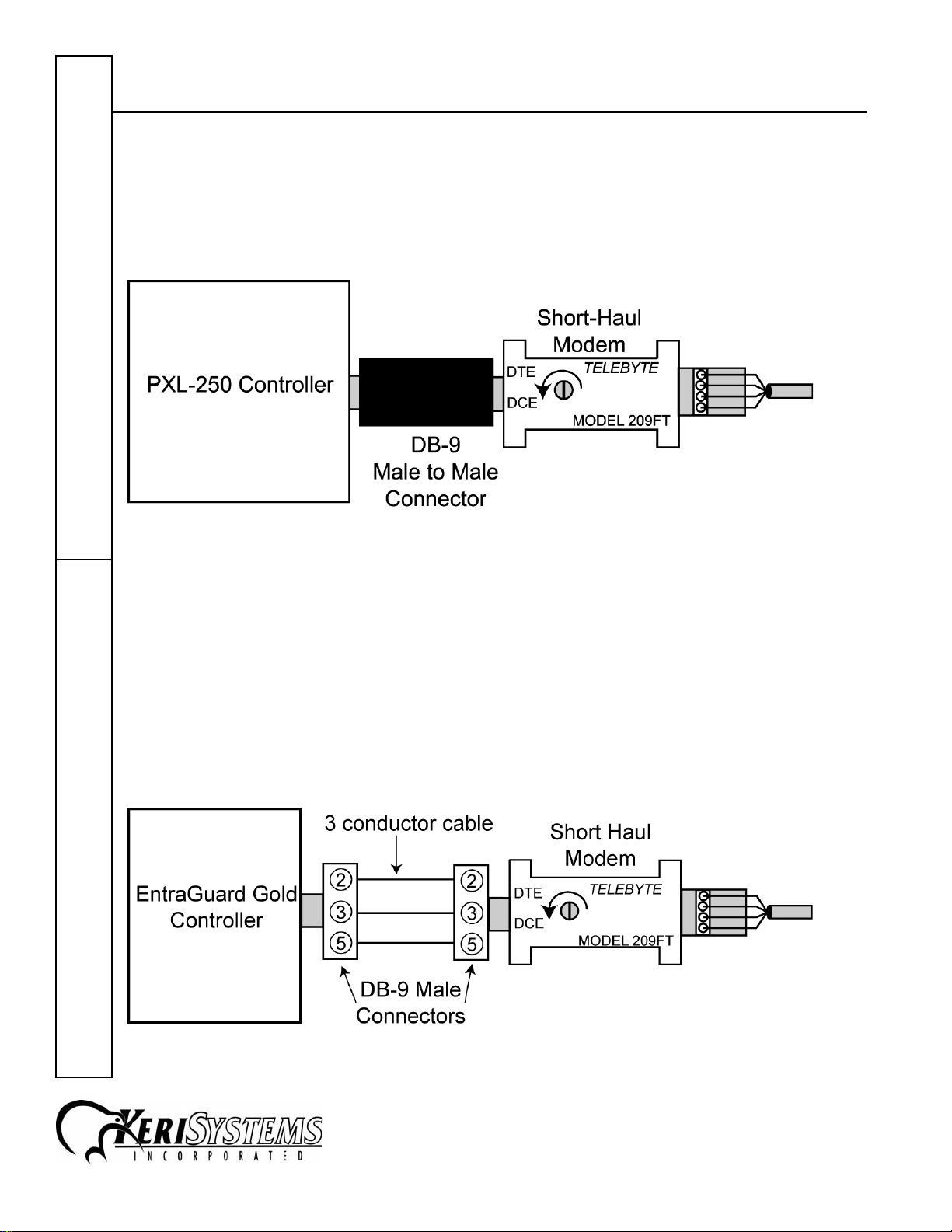
2.1 Connecting to a PXL-250 Controller
The DB-9 connector on the short haul modem and on the PXL-250 controller are both female. To
make the short haul modem to controller connection a DB-9 male-to-male connector is provided
(see Figure 1). Set the switch on the short haul modem to the DCE position by gently turning the
switch completely counter-clockwise.
Quick Start Guide
Figure 1: PXL-250 Controller to Short Haul Modem Connection
2.2 Connecting to an EntraGuard Gold Controller
A short haul modem may be used with an EntraGuard Gold master controller however, due to the
size of the short haul modem, an extension cable must be made to allow the modem to be located
outside of the controller box so the box may close properly.
The DB-9 connector on the short haul modem and on the EntraGuard Gold controller are both
female. To make the short haul modem to controller connection two DB-9 male connectors are
required and a minimum of 3 conductor cable (length as needed). Set the switch on the short haul
modem to the DCE position by gently turning the switch completely counter-clockwise.
Short Haul Modem
Figure 2: EntraGuard Gold Controller to Short Haul Modem Connection
2305 Bering Drive 01850-001 Rev. G
San Jose, CA 95131 USA
(800) 260-5265 (408) 435-8400 FAX (408) 577-1792
Web: www.kerisys.com E-mail: sales@kerisys.com Page 2 of 5
Page 3

Telebyte 209 Short Haul Modem
2.3 Connecting to the Host Computer - DB-9 to DB-9
If the host computer's COM port uses a male DB-9 connector the short haul modem can be plugged
directly to the COM port (see Figure 2). Set the switch on the short haul modem to the DCE
position by gently turning the switch completely counter-clockwise.
Figure 3: Host Computer to Short Haul Modem Connection
2.4 Connecting to the Host Computer - DB-9 to DB-25
If the host computer's COM port uses a DB-25 connector a DB-25 to DB-9 reduction plug must be
used.
2.4.1 Using a "Straight-Through" Reduction Plug
If the reduction plug uses straight-through wiring (pins 2 and 3 on the 25 pin side go straight
through to pins 2 and 3 on the 9 pin side) make the connection as shown in Figure 3. Set the switch
on the modem to the DTE position by gently turning the switch completely clockwise.
Figure 4: Host Computer to Short Haul Modem Connection Straight–Through Reduction
Plug
Short Haul ModemQuick Start Guide
2305 Bering Drive 01850-001 Rev. G
San Jose, CA 95131 USA
(800) 260-5265 (408) 435-8400 FAX (408) 577-1792
Web: www.kerisys.com E-mail: sales@kerisys.com Page 3 of 5
Page 4

Telebyte 209 Short Haul Modem
2.4.2 Using a "Twist" Reduction Plug
If the reduction plug uses 2-3 twist wiring (pin 2 on the 25 pin side goes to pin 3 on the 9 pin side
and pin 3 on the 25 pin side goes to pin 2 on the 9 pin side) make the connection as shown in Figure
4. Set the switch on the short haul modem to the DCE position by gently turning the switch
completely counter-clockwise.
Quick Start Guide
Figure 5: Host Computer to Short Haul Modem Connection 2–3 Twisted Reduction Plug
Short Haul Modem
2305 Bering Drive 01850-001 Rev. G
San Jose, CA 95131 USA
(800) 260-5265 (408) 435-8400 FAX (408) 577-1792
Web: www.kerisys.com E-mail: sales@kerisys.com Page 4 of 5
Page 5

Telebyte 209 Short Haul Modem
2.5 Short Haul Modem to Short Haul Modem Wiring
Two sets of twisted pair cables are used to connect the short haul modems. Connect the cable
between the two modems as shown in Figure 5. The shield wire is not connected at either end of the
cable.
Figure 6: Short Haul Modem to Short Haul Modem Wiring Diagram
End of document.
Short Haul ModemQuick Start Guide
2305 Bering Drive 01850-001 Rev. G
San Jose, CA 95131 USA
(800) 260-5265 (408) 435-8400 FAX (408) 577-1792
Web: www.kerisys.com E-mail: sales@kerisys.com Page 5 of 5
 Loading...