

Page 1

Keri Systems
PXL-250 Tiger Controller
and SB-293 Satellite Board
Technical Reference Manual v5.5
$39.00 USD
Page 2

© 1999, 2000, 2001 Keri Systems, Inc. - ALL RIGHTS RESERVED
Document Number 01836-004, Revision 5.5 – March, 2003
Keri Systems, PXL-250, SB-293, Tiger Controller
Windows is a trademark of Microsoft Corporation.
Other product names are trademarks or registered trademarks of their owners.
Keri Systems, Inc. reserves the right to change, without notice, product offerings or specifications.
No part of this publication may be reproduced in any form without permission from Keri Systems, Inc.
, and
Doors
are trademarks of Keri Systems, Inc.
Page 3

Keri Systems, Inc. Technical Reference Manual – PXL-250 and SB-293
Table of Contents
Features. . . . . . . . . . . . . . . . . . . . . . . . . . . . . . . . . . . . . . . . . . . . . . . 11
The PXL-250 Tiger Controller . . . . . . . . . . . . . . . . . . . . . . . . . . . . . . . . . . . 11
The SB-293 Satellite Board . . . . . . . . . . . . . . . . . . . . . . . . . . . . . . . . . . . . . 13
Proximity - Principle of Operation . . . . . . . . . . . . . . . . . . . . . . . . . . 16
Specifications . . . . . . . . . . . . . . . . . . . . . . . . . . . . . . . . . . . . . . . . . . 17
Unit Dimensions . . . . . . . . . . . . . . . . . . . . . . . . . . . . . . . . . . . . . . . . . . . . . . 17
Operating Temperature/Humidity Range . . . . . . . . . . . . . . . . . . . . . . . . . . . 17
Controller Power Requirements . . . . . . . . . . . . . . . . . . . . . . . . . . . . . . . . . . 17
Current Draw . . . . . . . . . . . . . . . . . . . . . . . . . . . . . . . . . . . . . . . . . . . . . . . . 18
Controller Memory Retention. . . . . . . . . . . . . . . . . . . . . . . . . . . . . . . . . . . . 18
Output Relay Contact Rating . . . . . . . . . . . . . . . . . . . . . . . . . . . . . . . . . . . . 18
Input Device Configuration . . . . . . . . . . . . . . . . . . . . . . . . . . . . . . . . . . . . . 18
Cable Requirements . . . . . . . . . . . . . . . . . . . . . . . . . . . . . . . . . . . . . 19
RS-232 Serial Cable . . . . . . . . . . . . . . . . . . . . . . . . . . . . . . . . . . . . . . . . . . . 19
RS-485 Network Cable. . . . . . . . . . . . . . . . . . . . . . . . . . . . . . . . . . . . . . . . . 19
Input Power. . . . . . . . . . . . . . . . . . . . . . . . . . . . . . . . . . . . . . . . . . . . . . . . . . 19
Earth Ground. . . . . . . . . . . . . . . . . . . . . . . . . . . . . . . . . . . . . . . . . . . . . . . . . 19
Keri Systems Proximity Readers . . . . . . . . . . . . . . . . . . . . . . . . . . . . . . . . . 20
Wiegand Compatible Devices . . . . . . . . . . . . . . . . . . . . . . . . . . . . . . . . . . . 20
Input and Output Connections . . . . . . . . . . . . . . . . . . . . . . . . . . . . . . . . . . . 20
PC/Doors Access Control Software Requirements . . . . . . . . . . . . . 21
Photo Badge Management Requirements. . . . . . . . . . . . . . . . . . . . . . . . . . . 21
System Cautions . . . . . . . . . . . . . . . . . . . . . . . . . . . . . . . . . . . . . . . . 22
Earth Ground. . . . . . . . . . . . . . . . . . . . . . . . . . . . . . . . . . . . . . . . . . . . . . . . . 22
Electromagnetic Interference . . . . . . . . . . . . . . . . . . . . . . . . . . . . . . . . . . . . 22
Power Supplies . . . . . . . . . . . . . . . . . . . . . . . . . . . . . . . . . . . . . . . . . . . . 22
EMI Sources . . . . . . . . . . . . . . . . . . . . . . . . . . . . . . . . . . . . . . . . . . . . . . 23
Separating Power Cables from Network and Reader Cables . . . . . . . . . 23
Transient Suppression. . . . . . . . . . . . . . . . . . . . . . . . . . . . . . . . . . . . . . . . . . 23
Communication with the Host Computer . . . . . . . . . . . . . . . . . . . . . . . . . . . 24
PC COM Port . . . . . . . . . . . . . . . . . . . . . . . . . . . . . . . . . . . . . . . . . . . . . 24
Ethernet TCP/IP . . . . . . . . . . . . . . . . . . . . . . . . . . . . . . . . . . . . . . . . . . . 24
PXL-250/SB-293 System Installation . . . . . . . . . . . . . . . . . . . . . . . 25
Advance Planning . . . . . . . . . . . . . . . . . . . . . . . . . . . . . . . . . . . . . . . . . . . . . 25
Utility Requirements. . . . . . . . . . . . . . . . . . . . . . . . . . . . . . . . . . . . . . . . . . . 25
Where Should Controllers be Installed? . . . . . . . . . . . . . . . . . . . . . . . . . . . . 25
Central Mounting . . . . . . . . . . . . . . . . . . . . . . . . . . . . . . . . . . . . . . . . . . 25
Distributed Mounting . . . . . . . . . . . . . . . . . . . . . . . . . . . . . . . . . . . . . . . 26
Installing the Enclosure . . . . . . . . . . . . . . . . . . . . . . . . . . . . . . . . . . . . . . . . 26
The Enrollment Reader. . . . . . . . . . . . . . . . . . . . . . . . . . . . . . . . . . . . . . . . . 26
Where Should Cables be Routed? . . . . . . . . . . . . . . . . . . . . . . . . . . . . . . . . 27
Revision 5.5 P/N: 01836-004 Page 3
Page 4

Technical Reference Manual – PXL-250 and SB-293 Keri Systems, Inc.
RS-485 Networking . . . . . . . . . . . . . . . . . . . . . . . . . . . . . . . . . . . . . . . . . . . 28
PXL-250W Jumper Settings . . . . . . . . . . . . . . . . . . . . . . . . . . . . . . . . . . . . . 28
SB-293 Jumper Settings . . . . . . . . . . . . . . . . . . . . . . . . . . . . . . . . . . . . . . . . 30
Installing the SB-293 Satellite Board onto the PXL-250 Controller . . . . . . 30
Wiring Connections to the Boards . . . . . . . . . . . . . . . . . . . . . . . . . . . . . . . . 31
Understanding Inputs and Outputs . . . . . . . . . . . . . . . . . . . . . . . . . . 32
Inputs . . . . . . . . . . . . . . . . . . . . . . . . . . . . . . . . . . . . . . . . . . . . . . . . . . . . . . 32
Door Status Switch Input . . . . . . . . . . . . . . . . . . . . . . . . . . . . . . . . . . . . 32
Request to Exit Input . . . . . . . . . . . . . . . . . . . . . . . . . . . . . . . . . . . . . . . 33
Auxiliary Request to Exit Input . . . . . . . . . . . . . . . . . . . . . . . . . . . . . . . 33
Global Unlock Input . . . . . . . . . . . . . . . . . . . . . . . . . . . . . . . . . . . . . . . . 33
General Purpose Input – SB-293 . . . . . . . . . . . . . . . . . . . . . . . . . . . . . . 34
Output Relays . . . . . . . . . . . . . . . . . . . . . . . . . . . . . . . . . . . . . . . . . . . . . . . . 35
Lock Relay . . . . . . . . . . . . . . . . . . . . . . . . . . . . . . . . . . . . . . . . . . . . . . . 35
Fail-Safe Lock. . . . . . . . . . . . . . . . . . . . . . . . . . . . . . . . . . . . . . . . . . 35
Fail-Secure Lock. . . . . . . . . . . . . . . . . . . . . . . . . . . . . . . . . . . . . . . . 36
Alarm Out Relay. . . . . . . . . . . . . . . . . . . . . . . . . . . . . . . . . . . . . . . . . . . 36
Door Held Open Relay . . . . . . . . . . . . . . . . . . . . . . . . . . . . . . . . . . . . . . 36
General Purpose Output Relay . . . . . . . . . . . . . . . . . . . . . . . . . . . . . . . . 37
Normally Closed Relay. . . . . . . . . . . . . . . . . . . . . . . . . . . . . . . . . . . 37
Normally Open Relay . . . . . . . . . . . . . . . . . . . . . . . . . . . . . . . . . . . . 37
Wiring Connections – PXL-250 . . . . . . . . . . . . . . . . . . . . . . . . . . . . 39
Terminal Block Connections . . . . . . . . . . . . . . . . . . . . . . . . . . . . . . . . . . . . 40
TB-5/TB-6 – Reader Connection . . . . . . . . . . . . . . . . . . . . . . . . . . . . . . . . . 41
Proximity Reader Connection. . . . . . . . . . . . . . . . . . . . . . . . . . . . . . . . . 41
Wiegand Compatible Reader Connection. . . . . . . . . . . . . . . . . . . . . . . . 42
TB-4 – Global Unlock or Auxiliary RTE Input Connection . . . . . . . . . . . . 45
Global Unlock. . . . . . . . . . . . . . . . . . . . . . . . . . . . . . . . . . . . . . . . . . . . . 45
Auxiliary RTE A-Door . . . . . . . . . . . . . . . . . . . . . . . . . . . . . . . . . . . . . . 46
TB-4 – Request to Exit Connection . . . . . . . . . . . . . . . . . . . . . . . . . . . . . . . 47
TB-4 – Door Status Switch Connection . . . . . . . . . . . . . . . . . . . . . . . . . . . . 48
TB-3 – Alarm Relay Connection . . . . . . . . . . . . . . . . . . . . . . . . . . . . . . . . . 50
TB-3 – Lock Relay Connection . . . . . . . . . . . . . . . . . . . . . . . . . . . . . . . . . . 52
TB-2 – Earth Ground/12 VDC Power Connection. . . . . . . . . . . . . . . . . . . . 54
TB-1 – RS-485 Controller Network Connection . . . . . . . . . . . . . . . . . . . . . 55
RS-232 Controller/PC Connection . . . . . . . . . . . . . . . . . . . . . . . . . . . . . . . . 57
Direct PC to Controller Serial Connection . . . . . . . . . . . . . . . . . . . . . . . 58
PC/DB-9F to PXL-250/DB-9M Direct Serial Connection . . . . . . . . 59
PC/DB-25F to PXL-250/DB-9M Direct Serial Connection . . . . . . . 60
Modem to Controller Serial Connection. . . . . . . . . . . . . . . . . . . . . . . . . 61
Modem/DB-25M to PXL-250/DB-9M Cable Wiring . . . . . . . . . . . 62
Modem/DB-9M to PXL-250/DB-9M Cable Wiring . . . . . . . . . . . . 63
Modem Adapter Cable Connection . . . . . . . . . . . . . . . . . . . . . . . . . 64
Modem to Personal Computer Serial Connection . . . . . . . . . . . . . . . . . 65
Modem/DB-25M to PC/DB-9F Cable Wiring . . . . . . . . . . . . . . . . . 66
Modem/DB-25M to PC/DB-25F Cable Wiring . . . . . . . . . . . . . . . . 67
Page 4 P/N: 01836-004 Revision 5.5
Page 5

Keri Systems, Inc. Technical Reference Manual – PXL-250 and SB-293
Modem/DB-9M to PC/DB-9F Cable Wiring . . . . . . . . . . . . . . . . . . 68
Modem/DB-9M to PC/DB-25F Cable Wiring . . . . . . . . . . . . . . . . . 69
Wiring Connections - SB-293. . . . . . . . . . . . . . . . . . . . . . . . . . . . . . 71
Terminal Block Connections . . . . . . . . . . . . . . . . . . . . . . . . . . . . . . . . . . . . 72
Two-Door Configuration . . . . . . . . . . . . . . . . . . . . . . . . . . . . . . . . . . . . . . . 73
TB-7 - Lock Relay Connection. . . . . . . . . . . . . . . . . . . . . . . . . . . . . . . . 73
TB-7 - Alarm Relay Connection. . . . . . . . . . . . . . . . . . . . . . . . . . . . . . . 75
TB-10 - Door Held Open Alarm Relay Connection . . . . . . . . . . . . . . . . 77
TB10 - General Purpose Output Relay Connections . . . . . . . . . . . . . . . 80
TB-8 - Door Status Switch Input Connection. . . . . . . . . . . . . . . . . . . . . 82
TB-8 - Request to Exit Input Connection . . . . . . . . . . . . . . . . . . . . . . . . 83
TB-8 - Auxiliary Request to Exit Input Connection. . . . . . . . . . . . . . . . 84
TB-8/TB-9 - General Purpose Input Connections . . . . . . . . . . . . . . . . . 85
Additional Inputs/Outputs Configuration . . . . . . . . . . . . . . . . . . . . . . . . . . . 87
TB-7/TB-10 - General Purpose Output Relay Connections . . . . . . . . . . 87
TB-8/TB-9 - General Purpose Input Connection . . . . . . . . . . . . . . . . . . 89
System Operation . . . . . . . . . . . . . . . . . . . . . . . . . . . . . . . . . . . . . . . 91
Powering the System for the First Time . . . . . . . . . . . . . . . . . . . . . . . . . . . . 91
Verify 12 VDC Supply Voltage . . . . . . . . . . . . . . . . . . . . . . . . . . . . . . . 91
Verify Wiegand Compatible Reader Supply Voltage. . . . . . . . . . . . . . . 92
Resetting the Controller's RAM . . . . . . . . . . . . . . . . . . . . . . . . . . . . . . . 92
Controllers with Modems . . . . . . . . . . . . . . . . . . . . . . . . . . . . . . . . . . . . 93
Normal Operation . . . . . . . . . . . . . . . . . . . . . . . . . . . . . . . . . . . . . . . . . . . . . 94
Viewing Controller Addresses . . . . . . . . . . . . . . . . . . . . . . . . . . . . . . . . . . . 94
Setting Controller Addresses . . . . . . . . . . . . . . . . . . . . . . . . . . . . . . . . . . . . 94
Master Controller Requirements. . . . . . . . . . . . . . . . . . . . . . . . . . . . . . . . . . 95
Proximity Reader Responses to Access Control Events. . . . . . . . . . . . . . . . 96
I/O Configuration . . . . . . . . . . . . . . . . . . . . . . . . . . . . . . . . . . . . . . . . . . . . . 96
Periodic Maintenance . . . . . . . . . . . . . . . . . . . . . . . . . . . . . . . . . . . . 97
Communication LEDs . . . . . . . . . . . . . . . . . . . . . . . . . . . . . . . . . . . . . . . . . 98
Power LEDs . . . . . . . . . . . . . . . . . . . . . . . . . . . . . . . . . . . . . . . . . . . . . . . . . 98
Fuse LED . . . . . . . . . . . . . . . . . . . . . . . . . . . . . . . . . . . . . . . . . . . . . . . . 98
Power/Voltage LED . . . . . . . . . . . . . . . . . . . . . . . . . . . . . . . . . . . . . . . . 99
Lock and Alarm LEDs . . . . . . . . . . . . . . . . . . . . . . . . . . . . . . . . . . . . . . . . . 99
Glossary . . . . . . . . . . . . . . . . . . . . . . . . . . . . . . . . . . . . . . . . . . . . . . 101
Index . . . . . . . . . . . . . . . . . . . . . . . . . . . . . . . . . . . . . . . . . . . . . . . . . 105
Revision 5.5 P/N: 01836-004 Page 5
Page 6

Technical Reference Manual – PXL-250 and SB-293 Keri Systems, Inc.
This page is intentionally left blank.
Page 6 P/N: 01836-004 Revision 5.5
Page 7

Keri Systems, Inc. Technical Reference Manual – PXL-250 and SB-293
Table of Figures
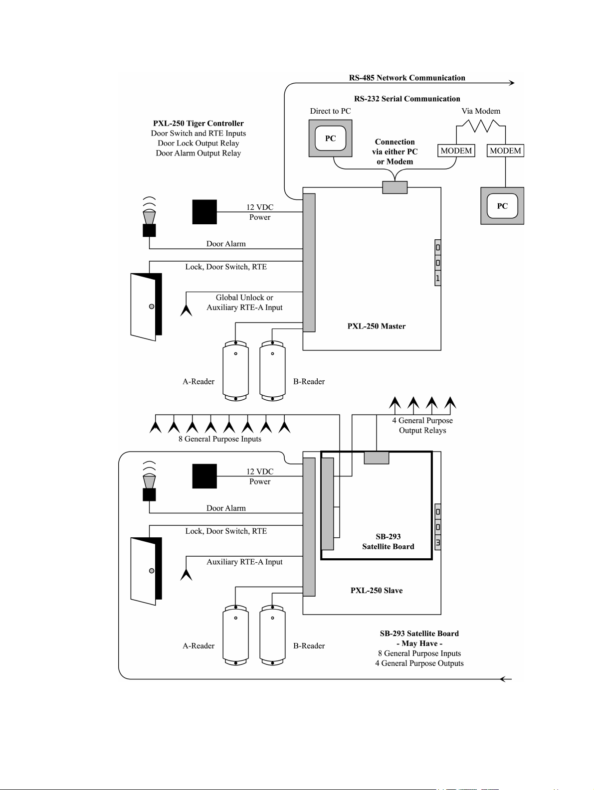
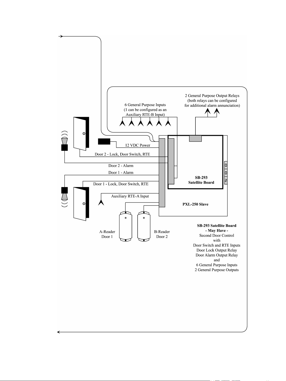
Figure 1-1: A Basic Access Control Network with Options . . . . . . . . . . . . . . . 14
Figure 1-1: A Basic Access Control Network with Options . . . . . . . . . . . . . . . 15
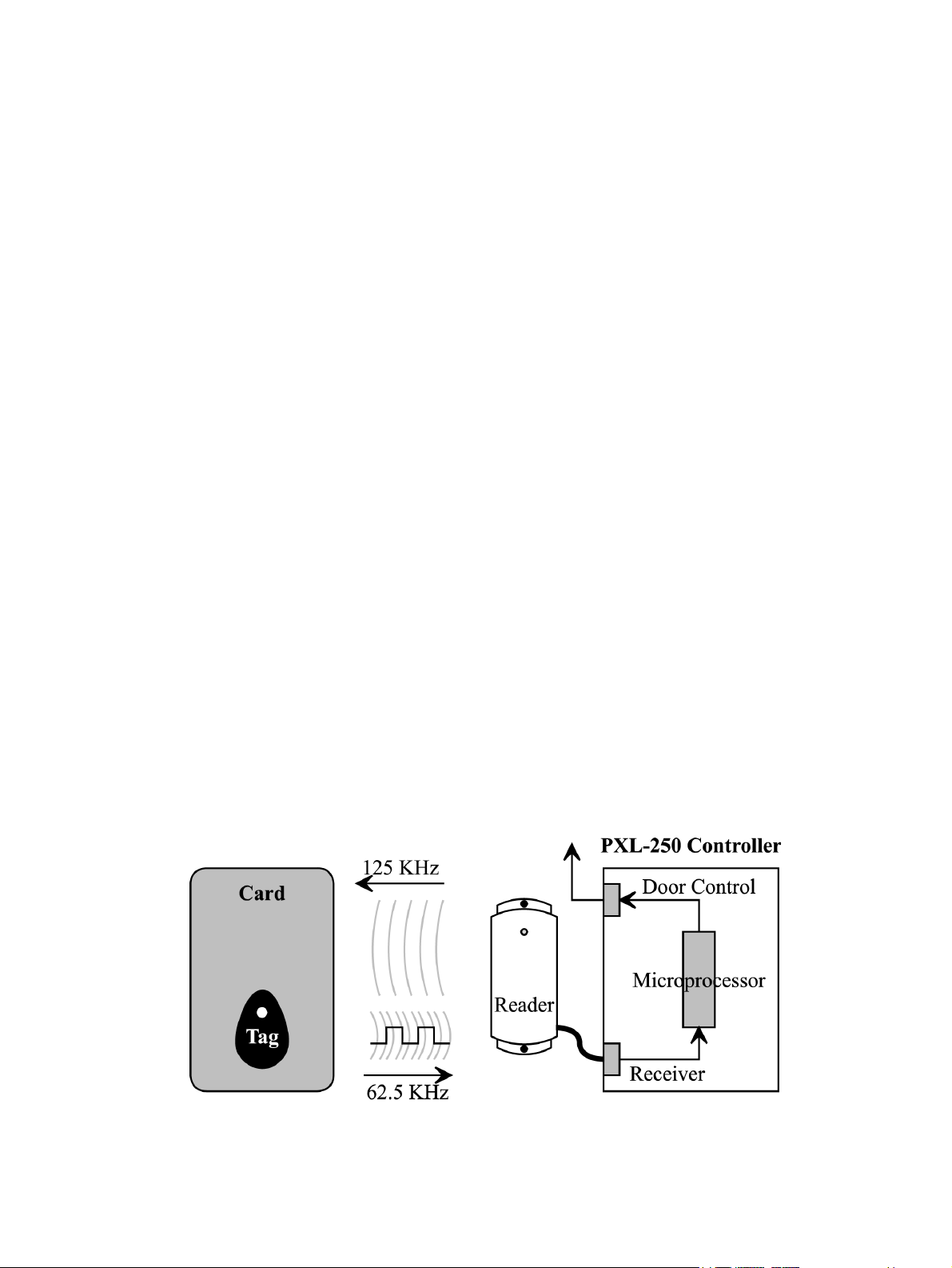
Figure 2-1: Proximity - Principle of Operation . . . . . . . . . . . . . . . . . . . . . . . . . 16
Figure 7-1: Setting the JP4 Jumper on PXL-250W Controllers . . . . . . . . . . . . . 29
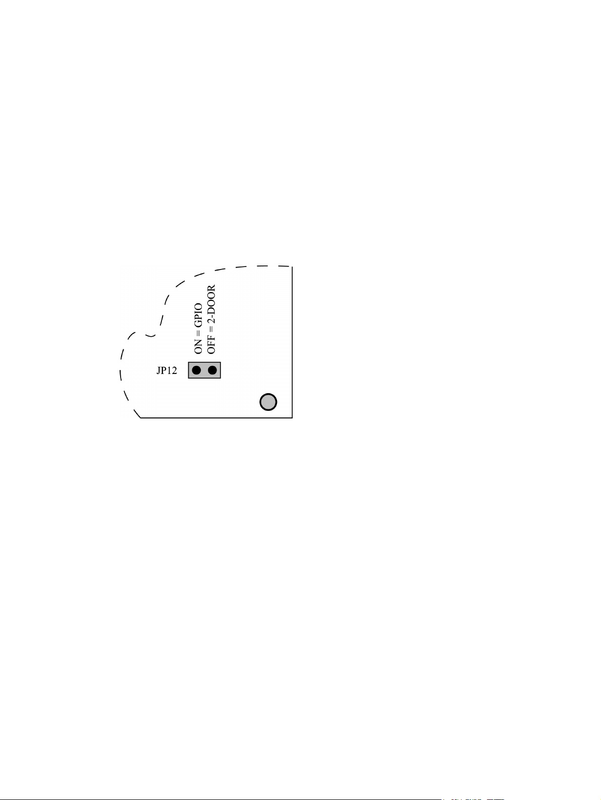
Figure 7-2: Setting JP12 . . . . . . . . . . . . . . . . . . . . . . . . . . . . . . . . . . . . . . . . . . . 30
Figure 7-3: Satellite Board/Controller Installation . . . . . . . . . . . . . . . . . . . . . . . 31
Figure 9-1: The PXL-250 Controller . . . . . . . . . . . . . . . . . . . . . . . . . . . . . . . . . 39
Figure 9-2: Installing Wiring and Removing a Terminal Block. . . . . . . . . . . . . 40
Figure 9-3: Keri Systems Proximity Reader Connections . . . . . . . . . . . . . . . . . 42
Figure 9-4: Wiegand Compatible Reader Connections . . . . . . . . . . . . . . . . . . . 42
Figure 9-5: Global Unlock Input Connections . . . . . . . . . . . . . . . . . . . . . . . . . . 45
Figure 9-6: Auxiliary RTE A-Door Input Connections . . . . . . . . . . . . . . . . . . . 46
Figure 9-7: Request to Exit Input Connections . . . . . . . . . . . . . . . . . . . . . . . . . 47
Figure 9-8: Door Status Switch Input Connections . . . . . . . . . . . . . . . . . . . . . . 49
Figure 9-9: Alarm Relay Output Connections . . . . . . . . . . . . . . . . . . . . . . . . . . 51
Figure 9-10: Fail-Safe Lock Relay Output Connections . . . . . . . . . . . . . . . . . . 52
Figure 9-11: Fail-Secure Lock Relay Output Connections . . . . . . . . . . . . . . . . 53
Figure 9-12: Earth Ground and 12 VDC Power Connections . . . . . . . . . . . . . . 54
Figure 9-13: RS-485 Network Communication Connections. . . . . . . . . . . . . . . 56
Figure 9-14: PC/DB-9F to PXL-250/DB-9M Cable Wiring . . . . . . . . . . . . . . . 59
Figure 9-15: PC/DB-25F to PXL-250/DB-9M Cable Wiring . . . . . . . . . . . . . . 60
Figure 9-16: Modem/DB-25M to PXL-250/DB-9M Cable Wiring . . . . . . . . . . 62
Figure 9-17: Modem/DB-9M to PXL-250/DB-9M Cable Wiring . . . . . . . . . . . 63
Figure 9-18: Modem/Adapter Cable/Controller Connection . . . . . . . . . . . . . . . 64
Figure 9-19: Modem/DB-25M to PC/DB-9F Cable Wiring. . . . . . . . . . . . . . . . 66
Figure 9-20: Modem/DB-25M to PC/DB-25F Cable Wiring. . . . . . . . . . . . . . . 67
Figure 9-21: Modem/DB-9M to PC/DB-9F Cable Wiring. . . . . . . . . . . . . . . . . 68
Figure 9-22: Modem/DB-9M to PC/DB-25F Cable Wiring. . . . . . . . . . . . . . . . 69
Figure 10-1: The SB-293 Satellite Board . . . . . . . . . . . . . . . . . . . . . . . . . . . . . . 71
Figure 10-2: Installing Wiring and Removing a Terminal Block. . . . . . . . . . . . 72
Figure 10-3: Fail-Safe Lock Relay Output Connections . . . . . . . . . . . . . . . . . . 73
Figure 10-4: Fail-Secure Lock Relay Output Connections . . . . . . . . . . . . . . . . 74
Figure 10-5: Alarm Relay Output Connections . . . . . . . . . . . . . . . . . . . . . . . . . 76
Figure 10-6: Door Held Open Alarm Relay Output Connections – A-Door . . . 78
Figure 10-7: Door Held Open Alarm Relay Output Connections – B-Door . . . 79
Figure 10-8: Normally Open General Purpose Relay Output Connections -
Two-Door Configuration . . . . . . . . . . . . . . . . . . . . . . . . . . . . . . . . . . . . . . . . . . 81
Figure 10-9: Normally Closed General Purpose Relay Output Connections -
Two-Door Configuration . . . . . . . . . . . . . . . . . . . . . . . . . . . . . . . . . . . . . . . . . . 81
Figure 10-10: Door Status Switch Input Connections . . . . . . . . . . . . . . . . . . . . 82
Figure 10-11: Request to Exit Input Connections . . . . . . . . . . . . . . . . . . . . . . . 83
Figure 10-12: Auxiliary Request to Exit Input Connections . . . . . . . . . . . . . . . 84
Figure 10-13: General Purpose Input Connections - Two-Door Configuration. 86
Revision 5.5 P/N: 01836-004 Page 7
Page 8

Technical Reference Manual – PXL-250 and SB-293 Keri Systems, Inc.
Figure 10-14: Normally Open General Purpose Relay Output Connections -
General Purpose I/O Configuration . . . . . . . . . . . . . . . . . . . . . . . . . . . . . . . . . . 88
Figure 10-15: Normally Closed General Purpose Relay Output Connections -
General Purpose I/O Configuration . . . . . . . . . . . . . . . . . . . . . . . . . . . . . . . . . . 88
Figure 10-16: General Purpose Input Connections - Additional I/O
Configuration . . . . . . . . . . . . . . . . . . . . . . . . . . . . . . . . . . . . . . . . . . . . . . . . . . . 90
Figure 11-1: Wiegand 12 VDC Warning LED. . . . . . . . . . . . . . . . . . . . . . . . . . 92
Figure 11-2: Close-Up of JP-3, S1, and Address Display LEDs . . . . . . . . . . . . 93
Figure 11-3: PXL-250 Controller Standard Operation Message . . . . . . . . . . . . 94
Figure 12-1: Modem/Controller Communication LEDs . . . . . . . . . . . . . . . . . . 97
Page 8 P/N: 01836-004 Revision 5.5
Page 9

Keri Systems, Inc. Technical Reference Manual – PXL-250 and SB-293
Tabl e o f Tables
Table1: Proximity Reader Current Draw . . . . . . . . . . . . . . . . . . . . . . . . . . . . . . 18
Table2: Maximum Cable Lengths by Wire Gauge for Keri Systems Proximity
Readers . . . . . . . . . . . . . . . . . . . . . . . . . . . . . . . . . . . . . . . . . . . . . . . . . . . . . . . . 20
Table3: Proximity Reader Connections . . . . . . . . . . . . . . . . . . . . . . . . . . . . . . . 41
Table4: Single-Line LED Wiegand Compatible Reader Connections . . . . . . . . 43
Table5: Dual-Line LED Wiegand Compatible Reader Connections . . . . . . . . . 43
Table6: Essex Keypad Wiegand Compatible Reader Connections . . . . . . . . . . 44
Table7: Global Unlock Input Connections . . . . . . . . . . . . . . . . . . . . . . . . . . . . . 45
Table8: Auxiliary RTE A-Door Input Connections . . . . . . . . . . . . . . . . . . . . . . 46
Table9: Request to Exit Input Connections . . . . . . . . . . . . . . . . . . . . . . . . . . . . 47
Table10: Door Status Switch Input Connections . . . . . . . . . . . . . . . . . . . . . . . . 48
Table11: Alarm Output Relay Connections . . . . . . . . . . . . . . . . . . . . . . . . . . . . 50
Table12: Lock Relay Output Connections . . . . . . . . . . . . . . . . . . . . . . . . . . . . . 52
Table13: Earth Ground and 12 VDC Power Connections . . . . . . . . . . . . . . . . . 54
Table14: RS-485 Network Communication Connections . . . . . . . . . . . . . . . . . 55
Table15: PC/DB-9F to PXL-250/DB-9M Cable Wiring . . . . . . . . . . . . . . . . . . 59
Table16: PC/DB-25F to PXL-250/DB-9M Cable Wiring . . . . . . . . . . . . . . . . . 60
Table17: Modem/DB-25M to PXL-250/DB-9M Cable Wiring . . . . . . . . . . . . . 62
Table18: Modem/DB-9M to PXL-250/DB-9M Cable Wiring . . . . . . . . . . . . . . 63
Table19: Modem/DB-25M to PC/DB-9F Cable Wiring . . . . . . . . . . . . . . . . . . 66
Table20: Modem/DB-25M to PC/DB-25F Cable Wiring . . . . . . . . . . . . . . . . . 67
Table21: Modem/DB-9M to PC/DB-9F Cable Wiring . . . . . . . . . . . . . . . . . . . 68
Table22: Modem/DB-9M to PC/DB-25F Cable Wiring . . . . . . . . . . . . . . . . . . 69
Table23: Lock Relay Output Connections . . . . . . . . . . . . . . . . . . . . . . . . . . . . . 73
Table24: Alarm Output Relay Connections . . . . . . . . . . . . . . . . . . . . . . . . . . . . 75
Table25: Door Held Open Alarm Output Relay Connections A-Door . . . . . . . 78
Table26: Door Held Open Alarm Output Relay Output Connections B-Door. . 79
Table27: General-Purpose Output Relay Connections – Two-Door
Configuration . . . . . . . . . . . . . . . . . . . . . . . . . . . . . . . . . . . . . . . . . . . . . . . . . . . 80
Table28: Door Status Switch Input Connections . . . . . . . . . . . . . . . . . . . . . . . . 82
Table29: Request to Exit Input Connections . . . . . . . . . . . . . . . . . . . . . . . . . . . 83
Table30: Auxiliary Request to Exit Input Connections . . . . . . . . . . . . . . . . . . . 84
Table31: General Purpose Input Connections – Two-Door Configuration . . . . 85
Table32: General-Purpose Output Relay Connections – Additional I/O
Configuration . . . . . . . . . . . . . . . . . . . . . . . . . . . . . . . . . . . . . . . . . . . . . . . . . . . 87
Table33: General-Purpose Input Connections – Additional I/O Configuration . 89
Table34: Proximity Reader Responses to Access Control Events . . . . . . . . . . . 96
Revision 5.5 P/N: 01836-004 Page 9
Page 10

Technical Reference Manual – PXL-250 and SB-293 Keri Systems, Inc.
This page is intentionally left blank.
Page 10 P/N: 01836-004 Revision 5.5
Page 11

Keri Systems, Inc. Technical Reference Manual – PXL-250 and SB-293
1.0 Features
NOTE: This Technical Reference manual was written to support a new revision of the
PXL-250 PCB (released July 2000). This PCB can be identified by its lack of a
removable receiver board on the lower left corner of the PCB. If you are working with
the previous revision of the PXL-250, please refer to v4.1 of the Technical Reference
manual (P/N 01836-003).
1.1 The PXL-250 Tiger Controller
The PXL-250 Tiger Controller is a smart entry controller which contains all the
intelligence and necessary inputs/outputs to manage one door and two readers. In an
access control system, from 1 to 128 PXL-250 controllers can be networked,
controlling from 1 to 128 doors. With the addition of a SB-293 Satellite Board, each
PXL-250 can manage a second door, one reader per door, for a possible total of 256
doors. Refer to Figure 1-1 on page 14 for a basic diagram of a PXL-250 access control
network and its options.
Standard PXL-250 features include:
Access Control
• one door (two doors if adding the SB-293 Satellite Board)
• two reader types
proximity or Wiegand
Inputs and Outputs
• three inputs
– door status switch
– request to exit (RTE)
AND EITHER
– global unlock or auxiliary RTE input (user configurable on the master
controller)
OR
– auxiliary RTE input (user configurable on slave controllers)
• two Form C output relays
– door lock
– door alarm
Quick Connect Wiring Connectors
• allows for quick removal of wiring connectors
• easy to change/upgrade wiring or the controller board following system
installation
Electrical Surge/Transient Protection
• Transorbs across all inputs and outputs (except relay outputs)
• MOVs across all relay outputs
Revision 5.5 P/N: 01836-004 Page 11
Page 12

Technical Reference Manual – PXL-250 and SB-293 Keri Systems, Inc.
Network Communications
• an RS-232 serial port that automatically configures itself to communicate directly
to a PC or communicate to a PC via modem
• an RS-485 network communication port capable of linking up to 128 controllers
on a single network up to 4,000 feet long (or up to 16,000 feet under specific
conditions – refer to Appendix 3: PXL-250 Network Wiring Application Note)
Automatic Network Configuration
• automatic configuration of earth ground to one point to support network
communications
Access Control Database Capacity
• transaction buffers capable of storing up to 3,640 events per controller
• a database capacity of up to 10,920 unique cardholders per controller, OR
• with optional RAM expansion, up to 65,535 unique cardholders per controller
Support for the Following Reader Technologies
• Keri Systems Proximity
• Wiegand Compatible (26-bit)
– Bar Code
– Biometrics
– Keypad
– Magnetic Stripe
– Other Proximity
NOTE: Wiegand readers must send data according to the Security Industry
Association's Wiegand Reader Interface Standard (document number AC-01D-96).
Keri Systems, Inc. cannot guarantee the performance or reliability of Wiegand readers
that do not meet these guidelines.
The optional LCD-1 Alpha/Numeric Plug-In Display adds the following feature.
• access to built-in system diagnostics to aid in troubleshooting (highly
recommended)
Page 12 P/N: 01836-004 Revision 5.5
Page 13

Keri Systems, Inc. Technical Reference Manual – PXL-250 and SB-293
1.2 The SB-293 Satellite Board
The SB-293 Satellite Board expands the capabilities of the PXL-250 Tiger Controller.
Depending upon the application, the SB-293 can add 8 general purpose inputs and 4
general purpose outputs, or it can add Door Switch and Request to Exit inputs and
Door Lock and Alarm outputs for a second door (one reader per door) with up to 6
additional general purpose inputs and up to two additional general purpose outputs.
Refer to Figure 1-1 on page 14 for a basic diagram of a PXL-250 access control
network and its options.
Standard features include:
In Second Door Access Control Configuration
• two doors, one reader per door (in conjunction with a PXL-250 controller)
• two door control inputs
– door switch status
– request to exit (RTE)
• six general purpose inputs
one can be user-configured for B-door Auxiliary RTE
• two Form C output relays
– door lock
– door alarm
• two general purpose, Form C, output relays
user-configurable for door held open and door forced alarm annunciation
In Additional Input/Output Configuration
• eight general purpose inputs
• four general purpose, Form C, output relays
Quick Connect Wiring Connectors
• allows for quick removal of wiring connectors
• makes it easy to change/upgrade wiring following system installation
Electrical Surge/Transient Protection
• transorbs across all inputs
• MOVs across all relay outputs
Revision 5.5 P/N: 01836-004 Page 13
Page 14
Technical Reference Manual – PXL-250 and SB-293 Keri Systems, Inc.
Figure 1-1: A Basic Access Control Network with Options
Page 14 P/N: 01836-004 Revision 5.5
Page 15
Keri Systems, Inc. Technical Reference Manual – PXL-250 and SB-293
Figure 1-1: A Basic Access Control Network with Options
Revision 5.5 P/N: 01836-004 Page 15
Page 16
Technical Reference Manual – PXL-250 and SB-293 Keri Systems, Inc.
2.0 Proximity - Principle of Operation
Proximity, also known as Radio Frequency Identification (RFID), is a method of
reading a card or tag without requiring any physical contact between the card/tag and
the reading device. With proximity readers there is no physical wear and tear on the
card/tag or the reading device. No inserting of a card/tag into a reader slot or swiping
of a card/tag through a reader slot is required. The card/tag is simply held up to a
reader, within the reader's detection range. Refer to Figure 2-1 for a diagram of this
process.
In a proximity reader application, a continuous 125 kHz electromagnetic field is
radiated from a coil inside the reader. This field is called the "excitation signal." When
a card/tag is presented to a reader, a coil inside the card/tag picks up the excitation
signal from the reader generating a small current in the card/tag's coil. This current
powers a small integrated circuit (IC) within the card/tag that holds a unique
identification number.
The coil in the card/tag transmits this identification number using a 62.5 kHz
electromagnetic field, one-half the value of the excitation signal. This 62.5 kHz signal
acts as an analog RF carrier for the digital ID number and is called the "receive signal"
as the coil in the reader receives this signal.
The reader passes the signal on to the RF receiver in the controller for decoding where
it is processed, error checked, and converted to a digital signal. The receiver then
sends the digital signal with the ID number to the microprocessor in the controller
where an access decision is made.
The read range for a key tag is approximately one-half that of a card. This is due to the
size of the coil in the tag compared to the coil in the card. Since the coil in the tag is
smaller, it needs to be closer to the excitation signal to activate the IC within the tag.
The bigger the coil in the card, tag, or reader, the greater the read range is likely to be.
Figure 2-1: Proximity - Principle of Operation
Page 16 P/N: 01836-004 Revision 5.5
Page 17

Keri Systems, Inc. Technical Reference Manual – PXL-250 and SB-293
3.0 Specifications
3.1 Unit Dimensions
• PXL-250 controller PCB – including wiring connectors
– 6.75 inches high by 6.00 inches wide by 2 inches deep
– 17.15 cm high by 15.25 cm wide by 5.08 cm deep
• PXL-250 controller PCB with an SB-293 Satellite Board – including wiring
connectors
– 7.25 inches high by 6.00 inches wide by 1.75 inches deep
– 18.45 cm high by 15.25 cm wide by 4.45 cm deep
• PXL-250 controller PCB with an LCD-1 Alpha/Numeric Display – including
wiring connectors
– 7.70 inches high by 6.00 inches wide by 1.75 inches deep
– 19.60 cm high by 15.25 cm wide by 4.45 cm deep
• PXL-250 controller PCB with an SB-293 Satellite Board and an LCD-1 Alpha/
Numeric Display
– 8.10 inches high by 6.00 inches wide by 1.75 inches deep, including wiring
connectors
– 20.60 cm high by 15.25 cm wide by 4.45 cm deep
•Enclosure
– 9.70 inches high by 8.20 inches wide by 2.60 inches deep
– 24.65 cm high by 20.85 cm wide by 6.60 cm deep
3.2 Operating Temperature/Humidity Range
• 0°F to 140°F (-18°C to 60°C)
• 0% to 90% Relative Humidity, non-condensing
3.3 Controller Power Requirements
• 12 VDC @ 1.0 A
Revision 5.5 P/N: 01836-004 Page 17
Page 18

Technical Reference Manual – PXL-250 and SB-293 Keri Systems, Inc.
3.4 Current Draw
• maximum current draw 270 mA for a controller plus reader current draw (refer to
Table 1 for Reader current draw)
• 120 mA max for a PXL-250 Controller
• 150 mA max for an SB-293 Satellite Board
Table 1: Proximity Reader Current Draw
Reader Type
MS-3000 MS-4000 MS-5000 MS-7000 MS-9000
Current
Draw
NOTE: If an electronic locking device (such as a magnetic lock, a door strike, or
similar device) is to be driven by the same power supply as the PXL-250 controller,
please ensure the power supply provides enough current to drive every device
connected to that supply plus an adequate safety margin. AC power cannot be used.
50 mA 50 mA 100 mA 200 mA 200 mA
3.5 Controller Memory Retention
• 5 year lithium battery back up to support controller RAM and real-time clock
3.6 Output Relay Contact Rating
• 1 Amp @ 24 VDC
3.7 Input Device Configuration
• Door Sense normally closed
• Request to Exit normally open
• Global Unlock normally open, or
Auxiliary RTE A-Door normally open
Page 18 P/N: 01836-004 Revision 5.5
Page 19

Keri Systems, Inc. Technical Reference Manual – PXL-250 and SB-293
4.0 Cable Requirements
4.1 RS-232 Serial Cable
• four conductor, shielded, stranded, AWG 24 wire (such as Belden 9534 or a larger
gauge)
• 50 feet maximum length (per RS-232 industry specification)
4.2 RS-485 Network Cable
• two conductor, shielded, twisted pair, stranded, AWG 24 wire (such as Belden
9501 or a larger gauge)
• 16,000 feet total network length
• refer to the Network Wiring Application Note (P/N 01824-002) for specific
network wiring information
4.3 Input Power
• two conductor, stranded, AWG 18 wire (such as Belden 8461 or a larger gauge)
• 200 feet maximum cable length for systems using an SB-293 with two readers
NOTE: On long power cable runs, the resistance in the cable itself causes a drop in
voltage at the end of the run. Be sure that your power supply does provide 12 VDC at
the end of the cable run.
4.4 Earth Ground
• single conductor, AWG 18 wire (or a larger gauge)
1
1. Ground wire is green with or without yellow tracer.
Revision 5.5 P/N: 01836-004 Page 19
Page 20

Technical Reference Manual – PXL-250 and SB-293 Keri Systems, Inc.
4.5 Keri Systems Proximity Readers
• six conductor, shielded, stranded, AWG 24 wire (such as Belden 9536 or a larger
gauge)
• maximum cable lengths by wire gauge are defined in Table 2
Table 2: Maximum Cable Lengths by Wire Gauge for Keri Systems
Reader Type 100 ft 250 ft 500 ft
1
Proximity Readers
Maximum Cable Length by Wire Gauge
MS-3000 AWG 24 AWG 24 AWG 24
MS-4000 AWG 24 AWG 24 AWG 24
MS-5000 AWG 24 AWG 24 AWG 24
MS-7000 AWG 24 AWG 24 AWG 20
MS-9000 AWG 24 AWG 22 AWG 18
4.6 Wiegand Compatible Devices
• five, six, or seven conductor, shielded, stranded, wire (depending upon the type of
Wiegand device)
NOTE: A minimum gauge of AWG 24 is required for data transfer with a 500-foot
maximum run length per Wiegand specification. However, the wire gauge to use
should be determined by the current draw requirements of the Wiegand device and the
actual length of the cable run. A +5 VDC Wiegand device must have +5 VDC at the
device (long cable runs have a voltage drop across the length of the run due to the
resistance in the cable). To ensure +5 VDC is available at the device a larger gauge of
wire (having less resistance) or a separate power supply at the Wiegand device may be
required.
4.7 Input and Output Connections
• two conductor, stranded, AWG 22 or a larger gauge
NOTE: The Lock Output relay may require a heavier gauge of wire depending upon
the current demands of the lock and the length of the lock wiring run.
NOTE: If plenum cable is required, please reference the Belden plenum equivalent to
the cables listed above.
1. The MS-4000 requires only four conductors as it does not have a beeper or LED.
Page 20 P/N: 01836-004 Revision 5.5
Page 21

Keri Systems, Inc. Technical Reference Manual – PXL-250 and SB-293
5.0 PC/Doors Access Control Software Requirements
For proper operation of the access control system, the host computer running the
Doors access control software must meet the following requirements.
• PC compatible computer using a Pentium-90 or faster microprocessor
• minimum of 16 MB of system RAM
• SVGA color monitor and SVGA graphics card. A minimum resolution of 800 x
600 is required for use with small fonts, or 1024 x 768 for use with large fonts.
• 3.5 inch floppy disk drive, CD-ROM, keyboard, and mouse or other pointing
device
• 50 MB of available hard disk space
• either a COM port with a 16550 UART to support an external modem or a direct
RS-232 serial connection; an internal 9600 baud or faster modem; or an Ethernet
2
card
• one of the following operating systems:
– Windows 95 – Windows 98 – Windows 2000
– Windows ME – Windows XP – Windows NT v4.0
1
Doors is incompatible with Windows 3.11, Windows NT v3.51, and MS-DOS. Doors
does not work with these operating systems.
5.1 Photo Badge Management Requirements
For proper operation of Doors in a badging application, the following requirements
must be met. These requirements supersede the standard PC/Doors requirements listed
above.
• The SVGA graphics card must be capable of displaying 65K colors to ensure
photo images are properly displayed.
• Between 100 MB and 1 GB of hard disk space must be available, depending upon
the number of card holders for which you will be providing photo badges.
•Either Windows 95, Windows 98, Windows 2000, Windows ME, or Windows NT
4.0 operating systems.
Proper USB support is not provided in Windows 95. In Windows 95, the digital
image capture device cannot be a USB device.
1. The larger the number of cards being enrolled, the larger the system RAM should be to
efficiently handle the card database.
2. Communication between the access control network and the
either the host computer’s COM port (COM 1, 2, 3, or 4), or a LAN/WAN Ethernet.
cannot operate if the host computer’s COM port is not operating correctly, or the LAN/WAN is
not set up properly. Keri Systems cannot be held responsible for host computer COM port,
hardware, or network problems.
Doors
software is done through
Doors
Revision 5.5 P/N: 01836-004 Page 21
Page 22

Technical Reference Manual – PXL-250 and SB-293 Keri Systems, Inc.
The TWAIN drivers that control communication between many digital cameras
and the badging software are not compatible with the Windows NT 4.0 operating
system. Alternate methods of digital image transfer may be necessary.
6.0 System Cautions
6.1 Earth Ground
You should make a quality earth ground connection to the PXL-250 controller to
ensure the best possible operating conditions for the controller. Without a quality earth
ground connection, the access control system may appear to operate correctly, but will
be extremely susceptible to transients and electromagnetic interference on data and
power lines. An earth ground brings all electrically neutral lines to the earth's surface
potential (essentially to a zero potential) providing three primary benefits to the PXL250 controller.
1. An earth ground protects the PXL-250 controller from electrical transients such as
power surges and lightning strikes (also providing a degree of safety for an
operator).
2. An earth ground provides a path to ground for electrical interference minimizing
data and communication problems for the reader data and network communication
lines.
3. Through a feature on the PXL-250 controller the shield for the entire RS-485
network is automatically grounded at one point on the master controller
minimizing communication problems.
Here are some possible sources for an earth ground.
• copper shrouded ground rod
• cold water pipe (must be a metal pipe - not PVC)
• steel building framing member (if the building's frame is embedded in the earth)
• electrical system ground (at the breaker/fuse box)
• telephone system ground
6.2 Electromagnetic Interference
Electromagnetic interference is electromagnetic energy radiated by an electrical
device that may affect the operation of other electrical devices. The PXL-250
controller can be sensitive to electromagnetic interference (EMI), affecting the
controller's performance. To ensure the best operating conditions for the controller,
please review and consider the following suggestions.
6.2.1 Power Supplies
Switching power supplies are known sources of EMI and cannot be used as the VDC
source for the PXL-250 controller or for any proximity reader.
Page 22 P/N: 01836-004 Revision 5.5
Page 23

Keri Systems, Inc. Technical Reference Manual – PXL-250 and SB-293
Only commercially built, linear, regulated power supplies should be used with
any access control system using proximity readers.
When installing a power supply for the PXL-250 controller, mount the power supply
three feet or greater from the controller to provide a degree of isolation from EMI that
may be generated by the power supply.
6.2.2 EMI Sources
Keri Systems also recommends installing the controller in low EMI areas whenever
possible. Always be cognizant of sources of EMI that may affect the operation of the
PXL-250 controller and install your controller away from these sources. Common
sources of EMI include computer monitors, electric motors, power transformers, and
air conditioning and heating units.
6.2.3 Separating Power Cables from Network and Reader Cables
To prevent EMI that may be conducted between power cables and network/reader
cables, Keri Systems recommends running the power cables apart from the network
and reader cables. This will minimize the possible effect a voltage surge on the power
cable may have on the network and reader cables.
6.3 Transient Suppression
Voltage transients are electrical surges or spikes conducted through power, input, or
output lines. Transients are generated when electric devices (such as electric locking
devices) are turned on or off. Transients may affect the operation of both the PXL-250
Controller and SB-293 Satellite board. Because of this, transient suppression is
required for both devices. A transient suppressor is a device added to an electrical
circuit that minimizes the affects of transients. Depending upon the application, a
transorb or an isolation relay provides the suppression necessary to ensure proper
operation of the access control system.
Under normal circumstances, a 1.5KE39C transorb must be installed across the
positive and negative power lines at the electric locking device to provide the best
operating conditions for the PXL-250 or SB-293. This transorb will minimize any
transients that may be generated by an electric locking device from affecting the
operation of the PXL-250 or SB-293. Two bipolar transorbs are provided with each
PXL-250 and each SB-293 for this purpose.
In applications such as parking gates or turnstiles (or any application using a large
electric motor), a transorb alone may not provide enough suppression; an isolation
relay may be required. Keri Systems offers an Isolation Relay Package (Keri Systems
P/N IRP-1) which can provide suppression for the large transients generated by these
types of devices.
Revision 5.5 P/N: 01836-004 Page 23
Page 24

Technical Reference Manual – PXL-250 and SB-293 Keri Systems, Inc.
6.4 Communication with the Host Computer
6.4.1 PC COM Port
A COM port is a hardware device that allows a computer to communicate with
external devices. To ensure proper communication between the access control system
and the PC, the PC's COM port must be configured properly and be operating
correctly. Most communication problems between PC and access control system are
directly attributable to an improperly configured or inoperable PC COM port. Please
ensure the PC COM port is working correctly before loading the Doors access control
software on your PC system.
Keri Systems cannot be held responsible for problems using the Doors access control
software that are due to an inoperable COM port. To assist in verifying basic COM
port operation, Keri Systems has provided a basic COM port test with the Doors
software package. COM port test instructions can be found with the documentation
supplied with the Doors software.
NOTE: Doors software only supports COM ports 1, 2, 3, or 4.
6.4.2 Ethernet TCP/IP
Ethernet connectivity is achieved by connecting the Entraguard master controller to a
LAN-100 Ethernet Module allowing the Entraguard network to be attached to a Local
Area Network (LAN) instead of directly to a computer. This gives any workstation on
a LAN (with the proper authority) the ability to communicate with the Entraguard
network.
Ethernet modules must be assigned an unique IP address which must be entered in
Doors for proper communication. One Ethernet module is necessary for each master
controller.
Utilizing Ethernet technology requires expertise. A LAN/WAN administrator or other
network professional is necessary. For further information please refer to the LAN/
WAN Ethernet Communication Application Note (P/N 01881-001). Keri Systems
does not provide technical support on network issues, please see your network
administrator for assistance.
Page 24 P/N: 01836-004 Revision 5.5
Page 25

Keri Systems, Inc. Technical Reference Manual – PXL-250 and SB-293
7.0 PXL-250/SB-293 System Installation
7.1 Advance Planning
A successful, easy to maintain installation requires advance planning - making sure the
site has everything necessary for a successful installation and making sure that all
materials are placed in easily maintainable locations that take advantage of the
features the PXL-250 access control network has to offer.
7.2 Utility Requirements
A successful installation needs:
• grounded power outlets for the PC system and controller power supplies
• dedicated analog telephone lines if communication between access control
network and PC is to be done via modem - one for the host PC system and one for
each master PXL-250 controller
NOTE: In most cases, modems are not compatible with private branch exchange
(PBX) telephone switching systems causing disconnection problems with the modem.
For this reason, dedicated analog telephone lines are required for successful modem
communication.
7.3 Where Should Controllers be Installed?
Controllers should be accessible for ease of installation and ease of maintenance.
Service closets may be a viable installation location. Controllers can be mounted
centrally, or distributed across an access control network.
7.3.1 Central Mounting
Central Mounting places all controllers in one location, running lengths of cables out
to each door to support the needed readers, inputs, and outputs. The benefit to central
mounting is that all controllers are together in one location making it easier to
maintain and secure the controllers. The drawback to central mounting is that it tends
to use more cable, routing cables from the controller to each door for the reader and
the necessary inputs and outputs. Accordingly, the cable costs for central mounting is
higher. Also, reader cable lengths are limited to 500 feet making central mounting in a
large installation difficult, if not impossible.
Revision 5.5 P/N: 01836-004 Page 25
Page 26

Technical Reference Manual – PXL-250 and SB-293 Keri Systems, Inc.
7.3.2 Distributed Mounting
Distributed Mounting places a controller near each door. The RS-485 network
communication cable is then routed to every controller on the access control network.
The benefit of distributed mounting is that less cable is needed for the reader and the
necessary inputs and outputs as they are all near the controller. Only the network cable
needs to be routed throughout the installation. The drawback to distributed mounting
is that a location needs to be found near each door for every controller. More effort
may be needed to maintain and secure the controllers.
All controllers need to be mounted in environmentally suitable locations. They require
protection from weather and from temperature/humidity extremes. If a PXL-250
controller is to be used outdoors, it must be installed in a watertight, weatherproof
enclosure. All controllers need at least three feet of separation between the controller
and the controller's power supply. This will prevent EMI radiated by the power supply
from affecting the performance of the controller.
7.4 Installing the Enclosure
The PXL-250 controller enclosure may be installed on any kind of wall material:
wood, sheet-rock, concrete, or metal. Mount the 12 VDC power supply for the PXL250 controller three feet or greater from the controller to provide a degree of isolation
from EMI that may be generated by the power supply. Always be aware of sources of
EMI that may affect the operation of the PXL-250 controller and make your
installations away from these sources whenever possible.
The enclosure's mounting holes are found at each corner of the unit (top left, top right,
bottom left, and bottom right). To mark a surface for drilling enclosure mounting
holes, simply place and hold the enclosure in the desired location and with a pencil or
scribe place a mark on the mounting surface at each mounting hole. Note the location
of the enclosure's knockouts (circular, removable plates on the enclosure's base plate)
and remove the knockout that allows you to route your cables into the enclosure in the
easiest, most direct path.
Page 26 P/N: 01836-004 Revision 5.5
Page 27

Keri Systems, Inc. Technical Reference Manual – PXL-250 and SB-293
7.5 The Enrollment Reader
The enrollment reader is the "A" reader on the master controller on the access control
network. The Doors access control software expects all card enrollment by
presentation information to come from the "A" reader on the master controller. For
ease of card enrollment, the enrollment reader and master controller should be
physically near the host computer running the Doors software.
The enrollment reader can be a Keri proximity reader or a Wiegand compatible device
reader. An enrollment reader is not necessary if all cards are block enrolled (block
enrollment uses the identification number printed on the body of the cards for
enrollment information so cards are not presented to an enrollment reader – block
enrollment assumes that the identification number on the card bodies are in
consecutive order).
The enrollment reader can be used at a door for access control as well as enrollment.
However, during the enrollment process the door or doors assigned to the master
controller become unavailable for access control; these doors remain in the state they
are in when the enrollment process begins (you may consider manually unlocking the
door before beginning enrollment and then relocking it when enrollment is complete).
Further, if the master controller has both "A" and "B" readers, it is possible for an
existing cardholder to present an already enrolled card at the B reader while an
operator is enrolling a card at the A reader. In this case, the card read by the B reader
will generate a "Card Already Enrolled" error message and the cardholder will not be
granted access through the door because the controller is in enrollment mode. For
these reasons, an installer may consider reserving the master controller and one reader
for card enrollment only.
7.6 Where Should Cables be Routed?
The PXL-250 controller offers flexibility in cabling options between optimizing cable
costs versus controller access/convenience. However there are several things to keep
in mind when routing cables for an installation:
DO
• Route cables in accessible areas whenever possible. This will make cable/system
maintenance easier.
• Add transient suppression across electric devices attached to the PXL-250 and SB293 output relays.
• Use an isolation relay (Keri Systems P/N IRP-1) if connecting to a parking gate,
turnstile, or any application using a large electric motor.
DO NOT
• Do not route cables near EMI sources. Cables can act as antennas, receiving EMI
that can affect controller performance.
• Do not stretch cables or route them over sharp edges.
Revision 5.5 P/N: 01836-004 Page 27
Page 28

Technical Reference Manual – PXL-250 and SB-293 Keri Systems, Inc.
7.7 RS-485 Networking
The PXL-250 uses a half-duplex, RS-485 communication bus. This is a very robust
system and has been tested to exceed standard RS-485 industry specifications. Using
approved cable and good installation practices, the network will operate satisfactorialy
with up to 16,000 feet of cable for systems of up to 128 PXL-250 controllers, each
with an SB-293. The following rules apply when wiring the controller network
communication bus.
1. The total network cable length cannot be greater than 16,000 feet.
2. Controllers can be connected in a single-run multi-drop, a star, mulitple stars, a
continuous daisy chain, etc.
3. The master controller can be located at any point in the network.
4. Care must be take to ensure the Tx- and Tx+ lines are not cross-wired.
5. Shield integrity must be maintained throughout the network installation.
6. If there are more wires than will reliably fit into the PXL-250 terminal block, Keri
recommends using an external terminal strip to combine the cables and then
connect a single wire to the terminal block.
7. The recommended cable is Belden 9501 or its equivalent. This is a single-pair,
twisted, shielded, AWG 24 cable.
Please refer to the PXL-250 Network Wiring Application Note (P/N 01824-002) in the
Appendix for detailed information on extended network configurations.
NOTE: Keri Systems defines a "Star" pattern as multiple sets of daisy chained
controllers all connected to the master controller at the center of the star.
NOTE: Communication buses such as RS-485 often appear to work even if installed
incorrectly, but can have intermittent problems making problem diagnosis difficult.
Failure to properly install an RS-485 network can result in network communication
errors and can cause the access control system to lock up. Although Keri Systems has
lab tested the functionality and data integrity of the extended network configurations,
no guarantees can be given for extended network configurations.
7.8 PXL-250W Jumper Settings
NOTE: Early revisions of the surface mount PXL-250W mislabeled the JP4 jumper as
JP5. All instructions for the JP4 jumper apply to the jumper labeled as JP5 (see
Figure 9-1 on page 39 for the location of the jumper).
On the PXL-250W controller (for use with Wiegand readers), there is only one jumper
that may require setting. JP4 sets the power supply voltage with which the controller
powers the reader (see Figure 7-1 on page 29 and Figure 9-1 on page 39).
Page 28 P/N: 01836-004 Revision 5.5
Page 29

Keri Systems, Inc. Technical Reference Manual – PXL-250 and SB-293
All Keri Systems proximity readers use 5 to 12 VDC power (except for the MS-9000
which uses 12 to 24 VDC power) while most Wiegand compatible readers use just 5
VDC power. For Wiegand configured PXL-250W controllers, there is a reader power
warning LED on the controller board to indicate if the controller is applying 12 VDC
to the Wiegand compatible reader (see Figure 7-1 on page 29). If your Wiegand
compatible reader does operate on 5 VDC no changes need to be made, the default
position for the jumper is to set power to 5 VDC. If your Wiegand compatible reader
requires 12 VDC, perform the following steps to set the reader supply voltage to 12
VDC.
When power is applied to the controller, the RDRPWR (reader power) warning LED
will turn on (see Figure 7-1) indicating 12 VDC is being supplied to the Wiegand
compatible reader.
JP4 - Wiegand Reader Power Supply Voltage
• Jumper across JP4 pins 1 and 2 to enable 12 VDC power for readers.
• Jumper across JP4 pins 2 and 3 enables 5 VDC power for readers. Most Wiegand
output devices require 5 VDC. This is the factory default setting for PXL-250W
controllers (to help ensure that 12 VDC is not accidentally applied to 5 VDC
Wiegand readers). If your Wiegand compatible reader requires 12 volts, move the
jumper from pins 2 and 3 to pins 1 and 2.
Figure 7-1: Setting the JP4 Jumper on PXL-250W Controllers
NOTE: Applying 5 VDC to a 12 VDC reader will not damage the 12 VDC reader.
However, applying 12 VDC to a 5 VDC reader very likely will damage the 5 VDC
reader. Be sure you are applying the correct supply voltage to the reader. Keri
Systems cannot be responsible for 5 VDC readers damaged by excessive voltage.
Revision 5.5 P/N: 01836-004 Page 29
Page 30
Technical Reference Manual – PXL-250 and SB-293 Keri Systems, Inc.
7.9 SB-293 Jumper Settings
On the SB-293 satellite board, there is only one jumper that may require setting. JP12
configures the satellite board for either second door control or for general purpose
inputs and outputs (see Figure 7-2, and Figure 10-1 on page 71).
• Placing a Jumper across JP12 pins 1 and 2 configures the satellite board for
general-purpose inputs and outputs.
• Removing the Jumper across JP12 configures the satellite board for second door
control with additional inputs and outputs. When the satellite board is configured
for second door control, the primary door must be connected to the "A" reader
(TB-5 on the PXL-250 controller board) and the secondary door must be
connected to the "B" reader (TB-6 on the controller board).
Figure 7-2: Setting JP12
7.10 Installing the SB-293 Satellite Board onto the PXL-250 Controller
Perform the following steps to install an SB-293 satellite board onto a PXL-250
controller.
1. Turn the controller's power OFF.
2. Line up the upper left-hand corners of the satellite and controller PCBs.
3. Line up the stand-offs in the top two corners of the satellite PCB with
corresponding mounting holes in the controller PCB (see Figure 7-3 on page 31).
4. Align the Satellite Board to Motherboard connector pins.
5. Gently press the two boards together with each stand-off into its mounting hole
and with the connector pins meshing together.
6. Turn the controller’s power ON.
7. If the J2 and P2 connectors have been meshed together properly, the LED on the
SB-293 (see Figure 10-1 on page 71) will turn green.
Page 30 P/N: 01836-004 Revision 5.5
Page 31

Keri Systems, Inc. Technical Reference Manual – PXL-250 and SB-293
Figure 7-3: Satellite Board/Controller Installation
7.11 Wiring Connections to the Boards
There are several things to keep in mind when making the wiring connections to the
PXL-250 and SB-293 boards.
When routing cables into and inside an enclosure:
DO
• Route cables in accessible areas whenever possible for ease of maintenance.
• Note the location of the enclosure's knockouts (circular, removable plates on the
enclosure's base plate) and remove the knockout that allows you to route your
cables into the enclosure in the easiest, most direct path.
• For a single door application, install the door's reader to the TB-5, "A" reader
connection on the controller.
• For a two door application, install the primary door's reader to the TB-5, "A"
reader connection on the controller and install the secondary door's reader to the
TB-6, "B" reader connection on the controller.
DO NOT
• Do not stretch or over-tension cables.
• Do not route cables over sharp objects.
• Do not route cables near EMI sources. Cables can act as antennas, receiving EMI
that can affect controller performance.
• Do not let the cables and the individual wires get tangled. Keep them neatly tied
back and clear from the controller PCB.
Revision 5.5 P/N: 01836-004 Page 31
Page 32

Technical Reference Manual – PXL-250 and SB-293 Keri Systems, Inc.
8.0 Understanding Inputs and Outputs
The following section provides descriptions of all Inputs and Outputs on the PXL-250
Controller and the SB-293 Satellite board. Wiring diagrams for all inputs and outputs
are included in the next section, Wiring Connections beginning on page 39.
8.1 Inputs
An input detects a state change generated by a device outside of the controller. The
controller then responds to that state change per commands programmed by the Doors
program. The input devices that generate the state change may be normally closed or
normally open.
A normally closed input device continually keeps a circuit closed or complete. A state
change is generated when the normally closed input device is opened, breaking the
circuit. In an access control system, a door switch is a typical example of a normally
closed device. While the door remains closed, the switch remains closed. When
someone opens the door, the door switch is opened, breaking the circuit and generating
a state change. The controller then responds to this state change per programmed
instructions and generates an output such as sounding an alarm if the door is a secure
door.
A normally open input device continually leaves a circuit open or incomplete. A state
change is generated when the normally open input device is closed, completing the
circuit. In an access control system, a request-to-exit (RTE) button is a typical example
of a normally open device. In an access control installation, an RTE button is located
on the secured side of the door. While there is no one at the door pressing the button,
the switch remains open. When someone desires to exit through a secure door, they
press the RTE button, closing the circuit and generating a state change. The controller
then responds to this state change per programmed instructions and generates an
output such as unlocking the door to allow exit.
8.1.1 Door Status Switch Input
The door status switch input accepts a signal from a normally closed input switch that
indicates the status of the door: open or closed. While the door remains closed, the
switch remains closed. When someone opens the door, the door switch is opened,
breaking the circuit and generating a state change. The controller responds to this state
change per programmed instructions and generates an alarm output if the door is
forced open or is held open too long. Refer to Figure 9-8 on page 49 (for the PXL-250)
and Figure 10-10 on page 82 (for the SB-293) for possible Door Status Switch wiring
diagrams.
NOTE: A door switch must be installed on any door to which anti-passback is being
applied. This allows the controller to properly track the anti-passback feature in the
Doors program.
Page 32 P/N: 01836-004 Revision 5.5
Page 33

Keri Systems, Inc. Technical Reference Manual – PXL-250 and SB-293
NOTE: If a Door Status switch is not being used, a jumper must be installed across
pins 1 and 2 of TB-4 (for the PXL-250 Controller) and pins 1 and 2 of TB-8 (for the
SB-293 Satellite board). This prevents a continuous Door Open signal from being
received by the controller and it ensures proper operation and annunciation of Door
Forced and Door Held Open alarms.
NOTE: If the Door Status input is being used, to ensure proper operation and
annunciation of Door Forced and Door Held Open alarms the door must also have a
Request to Exit input enabled.
8.1.2 Request to Exit Input
The request to exit (RTE) input accepts signals from a normally open input device that
indicates that a request has been made for someone to exit a secured door. Motion
detectors, pressure-sensitive floor mats, or push buttons may make RTE requests.
While there is no one there to activate an RTE request, the input remains open. When
someone desires to exit through a secure door, this person activates the RTE device,
closing the circuit and generating a state change. The controller then responds to this
state change per programmed instructions and generates an output unlocking the door
to allow exit. Refer to Figure 9-7 on page 47 (for the PXL-250) and Figure 10-11 on
page 83 (for the SB-293) for possible RTE wiring diagrams.
8.1.3 Auxiliary Request to Exit Input
Through an option in the Doors program, the general purpose input on the PXL-250
and general purpose input 3 on the SB-293 can be configured to provide an auxiliary
RTE input for an A-Door or a B-Door, respectively. This gives a person in a remote
location the ability to unlock a secure door (for example, an auxiliary RTE input at a
Receptionist’s desk that allows the Receptionist to unlock a secure door).
The auxiliary RTE Input works exactly like the standard RTE Input explained in the
previous section. Refer to Figure 9-6 on page 46 and Figure 10-12 on page 84 (for the
SB-293) for possible auxiliary RTE wiring diagrams.
NOTE: The PXL-250 has only one general purpose input. This input can be
configured for either Auxiliary RTE or for Global Unlock – but not both. Determine
which input application best suits the site requirements before installing input
hardware and wiring.
8.1.4 Global Unlock Input
Through an option in the Doors program, the general purpose input on the PXL-250
can be configured to perform a Global Unlock. A Global Unlock allows an operator to
unlock all doors, immediately (this input is only valid on the master PXL-250
Controller).
Revision 5.5 P/N: 01836-004 Page 33
Page 34

Technical Reference Manual – PXL-250 and SB-293 Keri Systems, Inc.
While there is no one there to activate a Global Unlock request, the input remains
open. When someone desires to globally unlock all doors, this person activates the
Global Unlock device (typically a normally open switch), closing the circuit and
generating a state change. The master controller then responds to this state change per
programmed instructions and generates an output unlocking all doors and allowing
exit. Refer to Figure 9-5 on page 45 for a possible Global Unlock wiring diagram.
NOTE: The Global Unlock input is not certified for use with fire systems. Please
check with local building codes regarding fire safety requirements.
8.1.5 General Purpose Input – SB-293
The general-purpose input accepts signals from either a normally closed or a normally
open input device that indicates when a change in state has occurred.
For a normally closed input device, while the input device is in its normal state the
general-purpose input circuit remains closed. When the input device is activated, the
general-purpose input circuit is opened generating a state change. The controller may
respond to this state change per programmed instructions. The general-purpose input
is configured through the Doors access control software.
A normally closed push-button may be used to provide a normally closed generalpurpose input. While the push-button is in its normal state, the normally closed circuit
is complete and no input signal is generated at the controller. When a user presses the
push button it opens the general-purpose input circuit and generates a state change.
The controller responds to this state change per programmed instructions and may
perform some action. Refer to Figure 10-9 on page 81 and Figure 10-15 on page 88 for
possible general-purpose, normally close Input wiring diagrams.
For a normally open input device, while the input device is in its normal state, the
general-purpose input circuit remains open. When the input device is activated, the
general-purpose input circuit is closed generating a state change. The controller may
respond to this state change per programmed instructions. The general-purpose input
is configured through the Doors access control software.
A normally open motion detector may be used to provide a normally open generalpurpose input. If the motion detector does not detect motion, its alarm circuit remains
open and no input signal is generated at the controller. When the motion detector does
detect someone entering its controlled area, its alarm circuit closes, completing the
general-purpose input circuit and generating a state change. The controller responds to
this state change per programmed instructions and may perform some action. Refer to
Figure 10-13 on page 86 and Figure 10-16 on page 90 for possible general-purpose,
normally open Input wiring diagrams.
Page 34 P/N: 01836-004 Revision 5.5
Page 35

Keri Systems, Inc. Technical Reference Manual – PXL-250 and SB-293
8.2 Output Relays
In many respects, a Form C output relay performs the opposite task of an input. An
input detects a state change generated by a device outside of the PXL-250 or SB-293.
An output relay, however, receives a signal from the controller that energizes the
output relay, switching its state. This state change typically prompts an action outside
of the controller. In most cases, inputs create state change signals that drive output
relays.
An example of this process is when a secure door is forced open. As the door is
opened, the door status switch opens. The door status switch input detects the switch's
state change. Programmed instructions within the controller send a signal instructing
the alarm relay to energize. The alarm relay switches its state to activate an audio
alarm notifying everyone in the immediate area that the door has been forced open. A
variety of devices may be activated by an output relay such as an electric door strike, a
magnetic lock, an alarm, a light, or a video camera.
A Form C relay has both normally closed and normally open circuits. When the relay
is not energized, the normally closed circuit is closed (allowing current flow) and the
normally open circuit is open. When the relay is energized the circuits switch roles; the
normally open circuit is closed (allowing current flow) and the normally closed circuit
is open. This dual nature of Form C relays (having both normally closed and normally
open circuits) allows for two types of applications outside the controller. A device may
be attached to the normally closed circuit so that it is always on until the relay
energizes to open the circuit and turn it off. Or, a device may be attached to the
normally open circuit so that it is always off until the relay energizes to turn it on.
8.2.1 Lock Relay
Unlocking a door is controlled by the Form C Lock Relay. When installing a door lock
there are two things to consider: safety versus security, or should the door be "failsafe" or "fail-secure."
8.2.1.1 Fail-Safe Lock
Fail-safe means that if the power should fail at a door (perhaps due to a power outage
or equipment failure), the door will automatically unlock allowing entrance and exit.
Power is required to keep the door locked. A fail-safe door ensures people will be able
to enter and exit a secured area through that door in the case of an emergency.
A typical fail-safe application may use a magnetic lock. In this application, the
controller energizes the lock relay, causing the lock relay to change its state. In its new
state the normally closed circuit is opened breaking the power to the magnetic lock
and allowing the door to be opened. Refer to Figure 9-10 on page 52 (for the PXL-
250) and Figure 10-3 on page 73 (for the SB-293) for possible fail safe Lock Relay
wiring diagram.
Revision 5.5 P/N: 01836-004 Page 35
Page 36

Technical Reference Manual – PXL-250 and SB-293 Keri Systems, Inc.
8.2.1.2 Fail-Secure Lock
Fail-secure means that if the power should fail at a door (perhaps due to a power
outage or equipment failure), the door will automatically lock and not allow entrance
but will continue to allow egress. Power is required to unlock the door. A fail-secure
door ensures a secured area remains secure regardless of the situation.
A typical fail-secure application may use a door strike. In this application, the
controller energizes the lock relay, causing the lock relay to change its state. In its new
state the normally open circuit is closed activating the release mechanism for the door
strike on the door to be opened. Refer to Figure 9-11 on page 53 (for the PXL-250) and
Figure 10-4 on page 74 (for the SB-293) for possible fail secure Lock Relay wiring
diagram.
8.2.2 Alarm Out Relay
Activating an audio (or a silent) alarm is controlled by the Form C alarm out relay. An
alarm condition causes the controller to energize the alarm out relay, causing the alarm
out relay to change its state. In its new state the normally open circuit is closed
activating the alarm. Refer to Figure 9-9 on page 51 (for the PXL-250) and Figure 105 on page 76 (for the SB-293) for possible Alarm Out Relay wiring diagram.
8.2.3 Door Held Open Relay
The Doors program allows the Alarm Out Relay to be configured for annunciating
both Door Forced and Door Held Open alarms or for annunciating only Door Forced
alarms. If the Alarm Out Relay is configured to only annunciate Door Forced alarms,
the Door Held Open condition is then configured for either annunciation on a separate
output relay or for no annunciation at all. If the Door Held Open Relay is configured to
be annunciated on a separate output relay (distinguishing it from a door forced alarm)
programming in the Doors program routes door held open alarms to designated
general-purpose output relays on the SB-293: TB-10, Pins 4, 5, and 6 for the A-Door
and TB-10, Pins 1, 2, and 3 for the B-Door.
A door held open condition causes the controller to energize the Door Held Open
relay, causing the relay to change its state. In its new state the normally open circuit is
closed activating the alarm. Refer to Figure 10-6 on page 78 and Figure 10-7 on
page 79 for a possible Door Held Open alarm relay wiring diagram.
Page 36 P/N: 01836-004 Revision 5.5
Page 37

Keri Systems, Inc. Technical Reference Manual – PXL-250 and SB-293
8.2.4 General Purpose Output Relay
A general-purpose output relay receives a signal from the controller that energizes the
output relay, switching its state. This state change typically initiates or ends an action
outside of the controller.
8.2.4.1 Normally Closed Relay
A device may be attached to the relay's normally closed circuit so that it is always on
until a signal from the controller energizes the relay, opening the circuit and turning
the device off. The general-purpose output relay is configured through the Doors
program.
A normally closed general-purpose output relay may be used to disable a remote
sensor. The controller opens the normally closed relay circuit based on programmed
instructions within the controller or from a direct command by an operator. The
opened circuit cuts power to the remote sensor, temporarily disabling it. Refer to
Figure 10-9 on page 81 and Figure 10-15 on page 88 for possible general-purpose
normally closed output wiring diagrams.
8.2.4.2 Normally Open Relay
A device may be attached to the relay's normally open circuit so that it is always off
until a signal from the controller energizes the relay, closing the circuit and turning the
device on. The general-purpose output relay is configured through the Doors access
control software.
A normally open general-purpose output relay may be used to activate a video camera.
The controller closes the normally open relay circuit based on programmed
instructions within the controller or from a direct command by an operator. The closed
circuit provides power to the video camera, allowing an operator to remotely view the
area covered by the camera. Refer to Figure 10-8 on page 81 and Figure 10-14 on
page 88 for possible general-purpose normally open output wiring diagrams.
Revision 5.5 P/N: 01836-004 Page 37
Page 38

Technical Reference Manual – PXL-250 and SB-293 Keri Systems, Inc.
This page is intentionally left blank.
Page 38 P/N: 01836-004 Revision 5.5
Page 39

Keri Systems, Inc. Technical Reference Manual – PXL-250 and SB-293
9.0 Wiring Connections – PXL-250
Before performing any wiring or connection operations, ensure that controller power
is OFF. Serious damage to sensitive components on the controller may occur if wiring
changes are made while controller power is on.
The following instructions assume that J1, the RS-232 serial port, is pointed up. With
one exception (the RS-232 serial port), all connections to the PXL-250 controller are
made on the left side of the unit (see Figure 9-1). Specific information for making each
wiring connection is provided throughout the rest of Section 9.
NOTE: It is the responsibility of the installation organziation to have only technically
qualified personnel performing the installation.
Figure 9-1: The PXL-250 Controller
Revision 5.5 P/N: 01836-004 Page 39
Page 40

Technical Reference Manual – PXL-250 and SB-293 Keri Systems, Inc.
9.1 Terminal Block Connections
Follow these instructions as you make your wiring connections. Select the wire to be
installed. Strip away 1/4 inch of insulation from the wire, place the wire into the
appropriate slot on the terminal block, and securely tighten the corresponding screw
on the top of the terminal block (see Figure 9-2). Make a firm connection, but be
careful not to over tighten the screw.
Figure 9-2: Installing Wiring and Removing a Terminal Block
All of the terminal blocks slide off the PXL-250 controller should it become necessary
to disconnect any installed cables. Firmly grasp the connector and pull it away from
the controller's printed circuit board (see Figure 9-2).
For a first-time installation, Keri recommends you make all wiring connections in the
following order, installing the wiring from the terminal block connections at the
bottom of the controller to the top. This will allow you to route and install the cables in
a sequential order and it ensures that an adequate earth ground is attached to the
controller before power is applied.
Page 40 P/N: 01836-004 Revision 5.5
Page 41

Keri Systems, Inc. Technical Reference Manual – PXL-250 and SB-293
9.2 TB-5/TB-6 – Reader Connection
The inputs on TB-5 accept wiring from Keri Systems proximity readers or from
Wiegand compatible devices. The standard PXL-250 uses Keri Systems proximity
readers. To use Wiegand compatible devices the Wiegand compatible version of the
PXL-250, the PXL-250W, must have been purchased.
A Wiegand compatible controller will have circuitry installed in the lower left corner
of the PCB, allowing the voltage supplied by the controller to the Wiegand reader to
be changed between 5 VDC and 12 VDC.
Two readers may be installed for one door to allow for access control in both
directions. The "A" reader, allowing entrance, is connected to TB-5 on the PXL-250
motherboard. The "B" reader, allowing exit, is connected to TB-6 on the motherboard.
If your application uses just one reader, connect it to TB-5 on the PXL-250
motherboard.
NOTE: If you are connecting readers for an elevator control application, please refer
to the Elevator Control Application Note (P/N 01878-001) in the appendix of this
document.
9.2.1 Proximity Reader Connection
Refer to Table 3 and Figure 9-3 and make the following connections to attach Keri
Systems proximity readers.
Table 3: Proximity Reader Connections
TB-5/TB-6 Description Wire Color
Pin 1 Antenna BLUE
Pin 2 Beeper GREEN
Pin 3 Reader Power RED
Pin 4 Reader Ground BLACK
Pin 5 Green LED BROWN
Pin 6 Red LED WHITE
Pin 7 NO CONNECTION n/a
Revision 5.5 P/N: 01836-004 Page 41
Page 42

Technical Reference Manual – PXL-250 and SB-293 Keri Systems, Inc.
Figure 9-3: Keri Systems Proximity Reader Connections
9.2.2 Wiegand Compatible Reader Connection
The PXL-250W controller can be configured to accept input from single-line LED,
dual-line LED, or Essex keypad Wiegand input devices (through the Doors software).
• For single-line LED devices, refer to Table 4 page 43 and Figure 9-4, and make the
following connections to attach Wiegand compatible readers.
• For dual-line LED devices, refer to Table 5 page 43 and Figure 9-4, and make the
following connections to attach Wiegand compatible readers.
• For Essex keypad devices, refer to Table 6 page 44 and Figure 9-4, and make the
following connections to connect Essex keypads.
Figure 9-4: Wiegand Compatible Reader Connections
NOTE: The wire colors called out in Figure 9-4 and in Tables 4, 5, and 6 are industry
standard wire colors. However, some manufacturers may not follow these industry
standard designations. Before installation, please refer to the Wiegand device’s
manual to see if the device’s wire colors follow the industry standard. If not, then
match the wire’s purpose to the callouts in Tables 4, 5, and 6 before installation.
NOTE: The Wiegand reader must send data according to the Security Industry
Association's Wiegand Reader Interface Standard (document number AC-01D-96).
Keri Systems, Inc. cannot guarantee the performance or reliability of Wiegand readers
that do not meet these guidelines.
Page 42 P/N: 01836-004 Revision 5.5
Page 43

Keri Systems, Inc. Technical Reference Manual – PXL-250 and SB-293
NOTE: All Keri Systems proximity readers can use between 5 and 12 VDC power
while most Wiegand compatible readers use 5 VDC power. Check your reader's
requirements and verify jumper JP4 is set correctly per the Jumper Settings
instructions on page 28. Early revisions of the surface mount PXL-250W mislabeled
the JP4 jumper as JP5. All instructions for the JP4 jumper apply to the jumper
labeled as JP5 (see Figure 9-1 on page 39 for the location of the jumper).
Table 4: Single-Line LED Wiegand Compatible
Reader Connections
TB-5/TB-6 Description Wire Color
Pin 1 Data 0 GREEN
Pin 2 Beeper
refer to reader
a
Pin 3 Reader Power RED
Pin 4 Reader Ground BLACK
Pin 5 n/a n/a
Pin 6 Single LED Line
refer to reader
a
Pin 7 Data 1 WHITE
a. Refer to the Wiegand compatible reader’s
documentation for the color of this wire.
Table 5: Dual-Line LED Wiegand Compatible
Reader Connections
TB-5/TB-6 Description Wire Color
Pin 1 Data 0 GREEN
Pin 2 Beeper
refer to reader
a
Pin 3 Reader Power RED
Pin 4 Reader Ground BLACK
Pin 5 Green LED
Pin 6 Red LED
refer to reader
refer to reader
a
a
Pin 7 Data 1 WHITE
a. Refer to the Wiegand compatible reader’s documentation
for the color of this wire.
Revision 5.5 P/N: 01836-004 Page 43
Page 44

Technical Reference Manual – PXL-250 and SB-293 Keri Systems, Inc.
Table 6: Essex Keypad Wiegand Compatible
Reader Connections
TB-5/TB-6 Description Wire Color
Pin 1 Data 0 GREEN
Pin 2 n/a
n/a
Pin 3 Reader Power RED
Pin 4 Reader Ground BLACK
Pin 5 n/a n/a
Pin 6 Single LED Line
refer to reader
Pin 7 Data 1 WHITE
a. Refer to the Wiegand compatible reader’s
documentation for the color of this wire.
a
Page 44 P/N: 01836-004 Revision 5.5
Page 45

Keri Systems, Inc. Technical Reference Manual – PXL-250 and SB-293
9.3 TB-4 – Global Unlock or Auxiliary RTE Input Connection
The global unlock or auxiliary RTE input is used in conjunction with the
programmable input/output feature of the Doors access control software. Refer to the
Inputs section starting on page 32 for more information on general-purpose inputs and
input devices. There are two possible uses for the general-purpose input.
• Global Unlock input (ONLY on the master controller – configured in the Doors
program)
• Auxiliary RTE input for the A-door (configured in the Doors program)
NOTE: The PXL-250 has only one general purpose input. This input can be
configured for either Auxiliary RTE or for Global Unlock – but not both. Determine
which input application best suits the site requirements before installing input
hardware and wiring.
9.3.1 Global Unlock
The normal state of the global unlock input is an open circuit that will be closed when
an input is generated. No voltage is applied at this input; the circuit will change state
(open to closed) to indicate an input event. Refer to the Global Unlock section starting
on page 33 for more information on global unlock. Refer to Table 7 and Figure 9-5 and
make the following connections to attach a global unlock input.
Table 7: Global Unlock Input
Connections
TB-4 Description
Pin 5 Ground/Common
Pin 6 Global Unlock Signal
Figure 9-5: Global Unlock Input Connections
Revision 5.5 P/N: 01836-004 Page 45
Page 46

Technical Reference Manual – PXL-250 and SB-293 Keri Systems, Inc.
9.3.2 Auxiliary RTE A-Door
The normal state of the auxiliary RTE A-door input is an open circuit that will be
closed when an input is generated. No voltage is applied at this input; the circuit will
change state (open to closed) to indicate an input event. Refer to the Auxiliary Request
to Exit section starting on page 33 for more information on auxiliary RTE. Refer to
Table 8 and Figure 9-6 and make the following connections to attach an auxiliary RTE
A-door input.
Table 8: Auxiliary RTE A-Door Input
Connections
TB-4 Description
Pin 5 Ground/Common
Pin 6 Auxiliary RTE A-Door Signal
Figure 9-6: Auxiliary RTE A-Door Input Connections
Page 46 P/N: 01836-004 Revision 5.5
Page 47

Keri Systems, Inc. Technical Reference Manual – PXL-250 and SB-293
9.4 TB-4 – Request to Exit Connection
Request to Exit (RTE - also known as REX) devices typically unlocks the door to
allow exit from the building. The PXL-250 controller may accept input from devices
such as switches, motion sensors, or floor mats. The normal state of this input is an
open circuit that will be closed when an input is generated. No voltage is applied at
this input; the circuit is completed to indicate an RTE event. Refer to the Request to
Exit Input starting on page 33 for more information on RTE inputs and input devices.
Refer to Table 9 and Figure 9-7 and make the following connections to attach an RTE
input.
Table 9: Request to Exit
Input Connections
TB-4 Description
Pin 2 Ground/Common
Pin 3 RTE Signal
Figure 9-7: Request to Exit Input Connections
NOTE: If a jumper lead from the door status switch input has already been installed
on TB-4, pin 2, loosen the terminal connector and insert the RTE input ground lead
beside the jumper lead.
Revision 5.5 P/N: 01836-004 Page 47
Page 48

Technical Reference Manual – PXL-250 and SB-293 Keri Systems, Inc.
9.5 TB-4 – Door Status Switch Connection
The Door Status switch indicates the state of the door (open or closed). The normal
state of this input is a closed circuit that will be opened when an input is generated. No
voltage is applied at this input; the circuit is opened and closed corresponding with the
door status. Refer to the Door Status Switch Input section starting on page 32 for more
information on Door Status Switch inputs and input devices.
Each PXL-250 is shipped with an installation kit including all necessary terminal
blocks and transorbs. One of these terminal blocks has a jumper across pins 1 and 2.
This terminal block is designated for use on TB-4. If a door switch is not used on the
controller, this jumper prevents a continuous door open status alarm from being
received by the controller. If a door switch is used, simply remove this jumper and
install the door switch leads.
Refer to Table 10 and Figure 9-8 on page 49 and make the following connections to
attach a door status input.
Table 10: Door Status Switch
Input Connections
TB-4 Description
Pin 1 Door Status Switch Signal
Pin 2 Ground/Common
NOTE: When using a Door Status input, the door must also have a Request to Exit
input for proper operation/annunciation of Door Forced and Door Held Open alarms.
NOTE: A Door Switch must be installed on any door to which anti-passback is being
applied for proper tracking of the anti-passback feature in the Doors program.
Page 48 P/N: 01836-004 Revision 5.5
Page 49
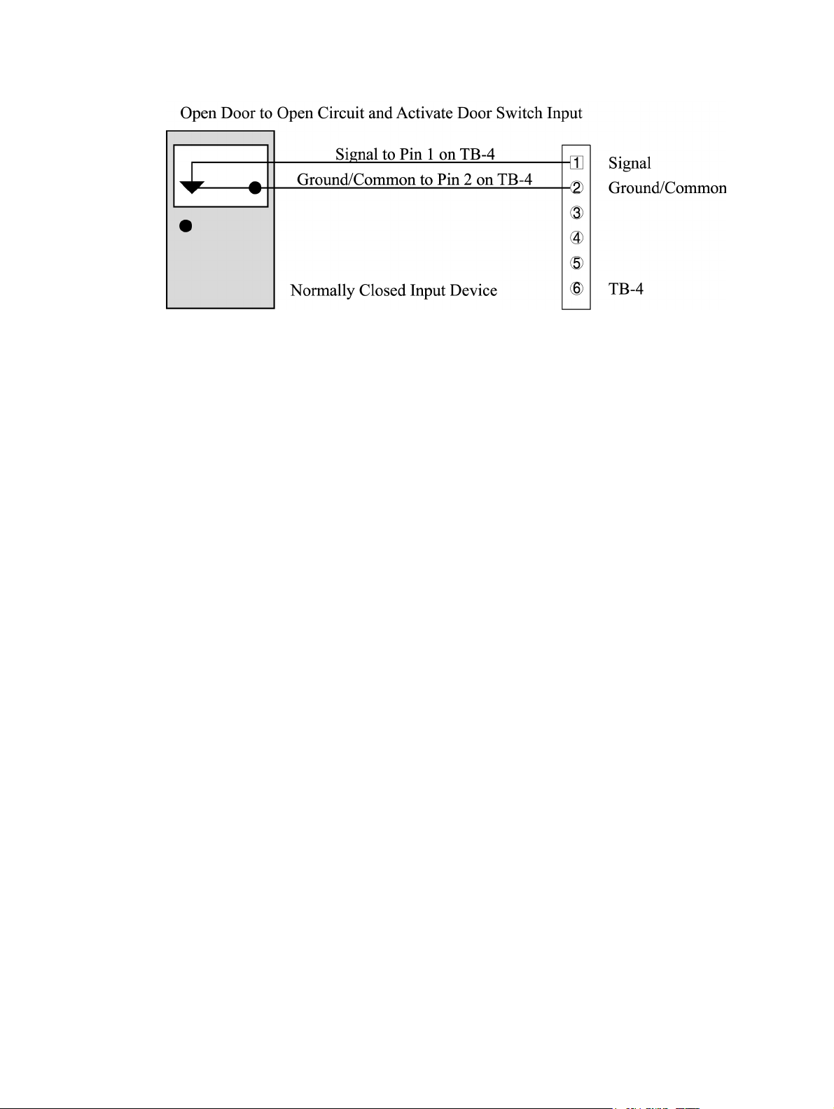
Keri Systems, Inc. Technical Reference Manual – PXL-250 and SB-293
Figure 9-8: Door Status Switch Input Connections
NOTE: If a ground lead from the Request To Exit input has already been installed on
TB-4, pin 2, loosen the terminal connector and insert the door status ground lead
beside the RTE input ground lead.
Revision 5.5 P/N: 01836-004 Page 49
Page 50

Technical Reference Manual – PXL-250 and SB-293 Keri Systems, Inc.
9.6 TB-3 – Alarm Relay Connection
The Alarm Relay is a Form C relay that provides an output to trigger an audible signal
(or a silent alarm) whenever the door is put into an alarm state (i.e. the door is forced
open). It is also used to trigger an audible signal (or a silent alarm) whenever the door
is held open too long (exceeding the Open Time set within the Doors access control
program). Depending upon the type of alarm being installed and your application,
your alarm may require a normally closed/common connection, a normally open/
common connection, or a normally closed/common/normally open connection. Every
application requires the common lead connection. Refer to the Alarm Relay output
section starting on page 36 for more information on Alarm relay outputs and output
devices.
NOTE: Default alarm annunciation sets this relay to annunciate both Door Forced
and Door Held Open alarms for the A-door. The enhanced alarm annunciation feature
(configured in the Doors program) allows for separate annunciation of Door Forced
and Door Held Open alarms. The A-door Door Forced alarm can be enabled at this
relay or disabled. The A-door Door Held Open alarm can be left to this relay,
disabled, or routed to a relay on an SB-293 Satellite board. Please refer to the Wiring
Connections – SB-293 section starting on page 71 for information on how to connect
these enhanced alarm annunciation outputs.
For a typical alarm relay installation, refer to Table 11 and Figure 9-9 on page 51 and
make the following wiring and transorb connections to attach the alarm relay.
Table 11: Alarm Output
Relay Connections
TB-3 Description
Pin 4 Normally-Open
Pin 5 Common
Pin 6 Normally-Closed
Page 50 P/N: 01836-004 Revision 5.5
Page 51
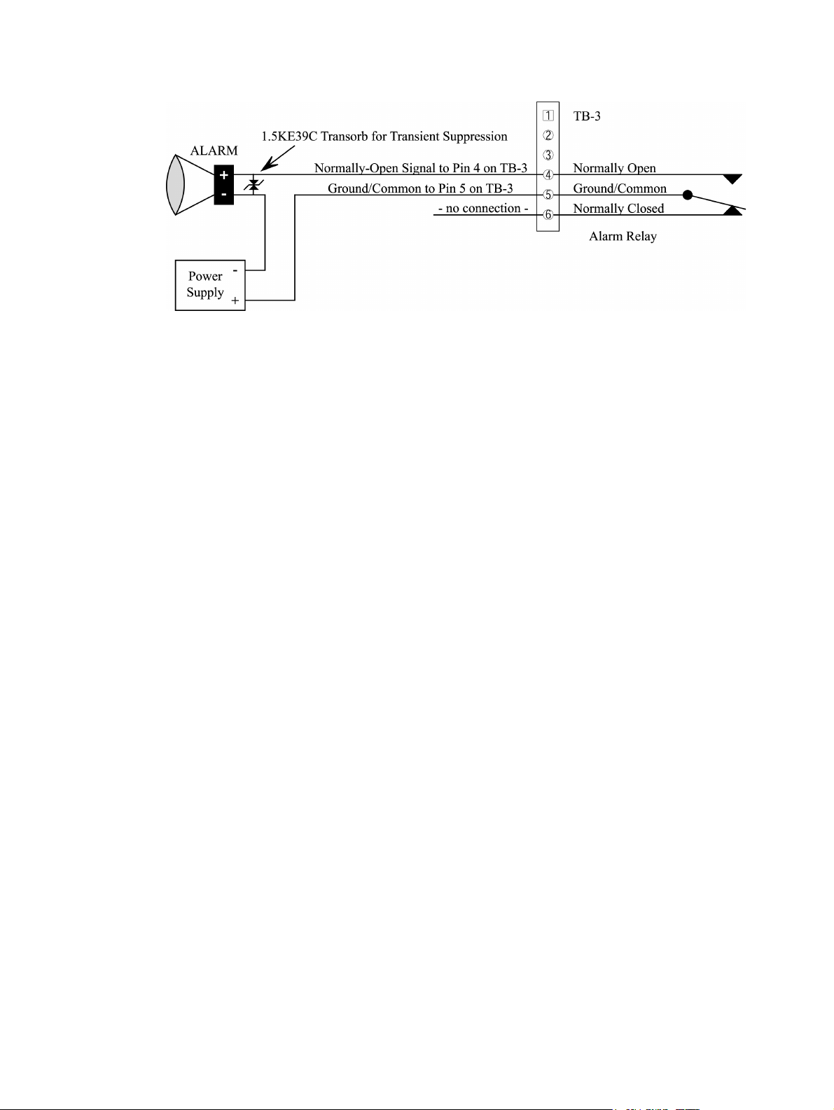
Keri Systems, Inc. Technical Reference Manual – PXL-250 and SB-293
Figure 9-9: Alarm Relay Output Connections
Revision 5.5 P/N: 01836-004 Page 51
Page 52

Technical Reference Manual – PXL-250 and SB-293 Keri Systems, Inc.
9.7 TB-3 – Lock Relay Connection
The Lock Relay is a Form C relay used to control the door lock. Please refer to the
Lock Relay output section starting on page 35 for more information on Lock Relays
and output devices.
For a typical fail-safe door lock relay installation, refer to Table 12 and Figure 9-10
and make the following wiring and transorb connections to attach the door lock relay.
Table 12: Lock Relay
Output Connections
TB-3 Description
Pin 1 Normally-Open
Pin 2 Common
Pin 3 Normally-Closed
Figure 9-10: Fail-Safe Lock Relay Output Connections
For a typical fail-secure door lock relay installation, refer to Table 12 and Figure 9-11
on page 53 and make the following wiring and transorb connections to attach the door
lock relay.
Page 52 P/N: 01836-004 Revision 5.5
Page 53
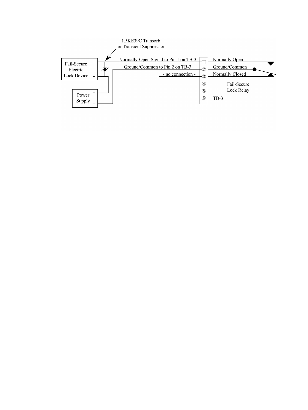
Keri Systems, Inc. Technical Reference Manual – PXL-250 and SB-293
Figure 9-11: Fail-Secure Lock Relay Output Connections
Revision 5.5 P/N: 01836-004 Page 53
Page 54
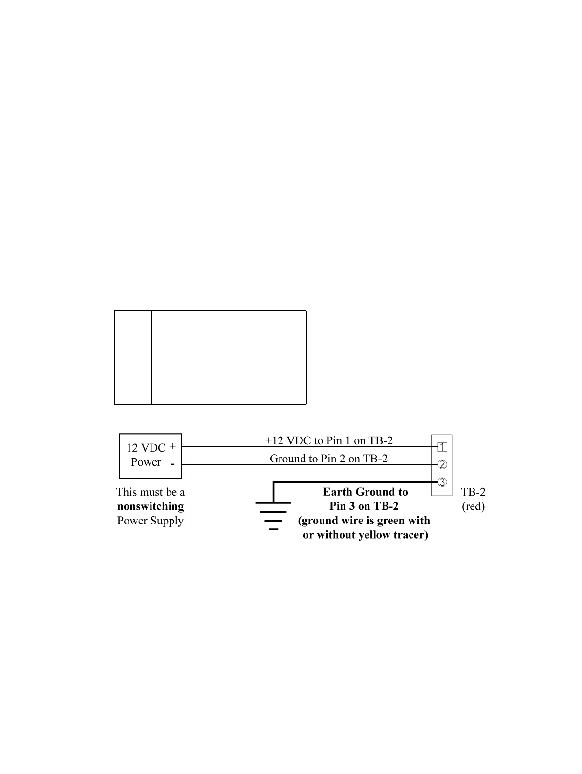
Technical Reference Manual – PXL-250 and SB-293 Keri Systems, Inc.
9.8 TB-2 – Earth Ground/12 VDC Power Connection
The PXL-250 controller requires 12 VDC power at 1 A. You should make a quality
earth ground connection to the controller prior to connecting the DC power lines. The
earth ground provides protection for the controller and ensures the best possible
operating conditions. Refer to the System Cautions – Earth Ground section starting on
page 22 for more information regarding earth grounding.
Possible sources for earth ground are a ground rod, a cold water pipe, a steel building
frame, the electrical system ground at the breaker/fuse box, or the telephone system
ground.
Refer to Table 13 and Figure 9-12 and make the following connection to attach the
earth ground and then the 12 VDC power lines.
Table 13: Earth Ground and 12 VDC
Power Connections
TB-2 Description
Pin 1
Pin 2 Negative 12 VDC Power Line
Pin 3 Earth Ground
Figure 9-12: Earth Ground and 12 VDC Power Connections
NOTE: Keri Systems does not recommend sharing a power supply between the PXL250 controller and an electric locking device. Transients generated as the electric
locking device is energized/de-energized can affect controller operation.
Positive 12 VDC Power Line
NOTE: The power TB-2 is colored red to make it easier to tell it apart from the
network connection (TB-1).
Page 54 P/N: 01836-004 Revision 5.5
Page 55

Keri Systems, Inc. Technical Reference Manual – PXL-250 and SB-293
9.9 TB-1 – RS-485 Controller Network Connection
All PXL-250 controllers communicate, controller-to-controller, through an RS-485
serial communication network. Up to 128 controllers can be attached to this network.
Refer to the RS-485 Networking section on page 28 for information regarding network
cable routing.
To provide the best operating conditions for the RS-485 communication network, the
PXL-250 controller automatically ties the network shield to earth ground at one point,
preventing ground loops.
Refer to Table 14 and Figure 9-13 on page 56 and make the following connections to
attach a network communication line.
Table 14: RS-485 Network
Communication Connections
TB-1 Description
Pin 1 Tx/Rx Negative
Pin 2 Tx/Rx Positive
Pin 3 Network Cable Shield
NOTE: Do NOT connect earth ground to the network cable shield. The PXL-250
controller automatically connects earth ground to the shield at one point on the
network. This single connection minimizes the effects of ground loops that can affect
controller performance.
NOTE: Keri Systems has identified specific extended network configurations that can
be used to wire a controller network communication bus (subject to certain
limitations). These configurations include a "star" pattern network communication
bus, a spur cable length of up to 5,000 feet, and a total network cable length of up to
16,000 feet. Refer to Addendum 3, PXL-250 Network Wiring Application Note (P/N
01824-002), for detailed information on extended network configurations.
Revision 5.5 P/N: 01836-004 Page 55
Page 56
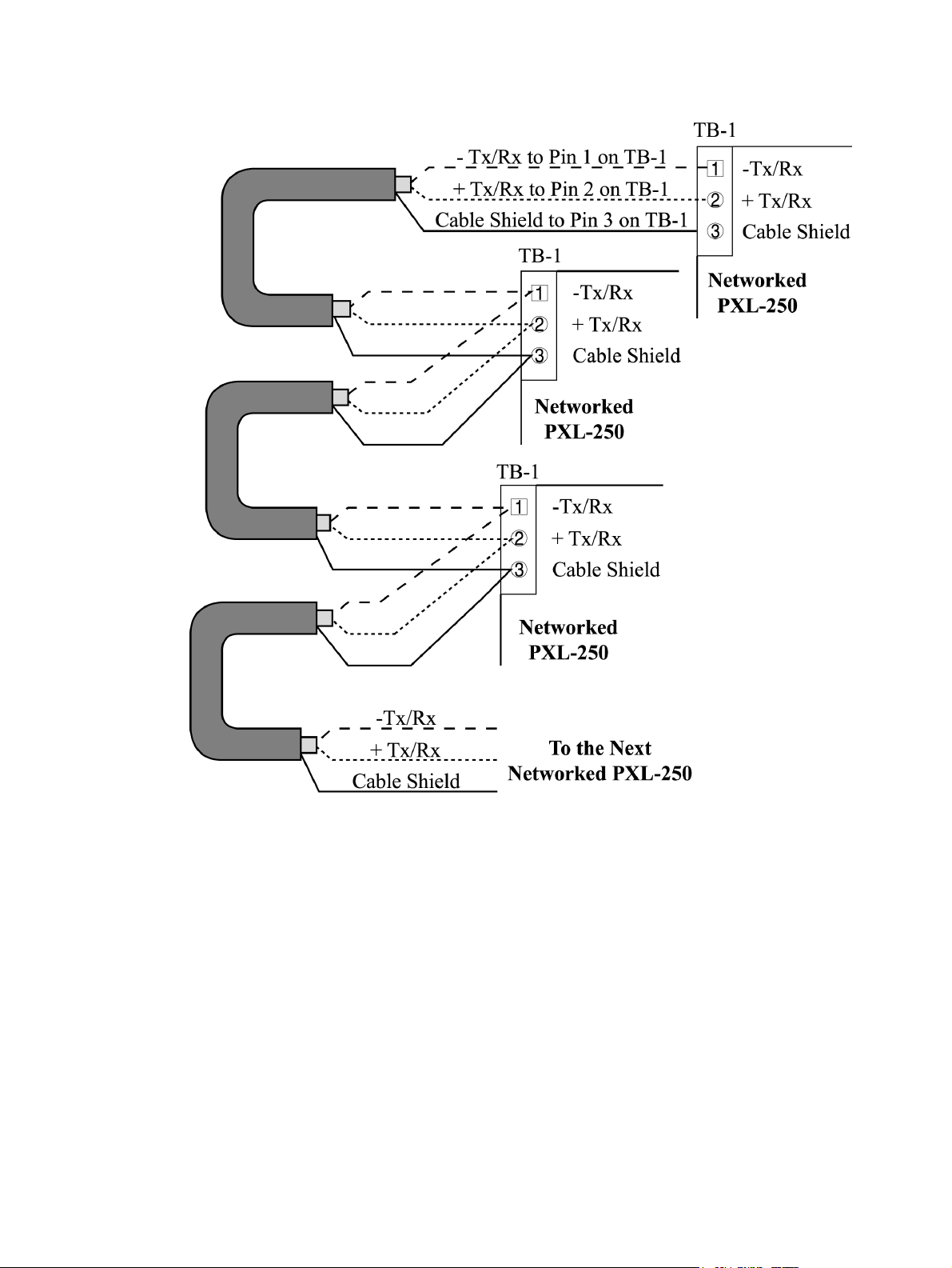
Technical Reference Manual – PXL-250 and SB-293 Keri Systems, Inc.
Figure 9-13: RS-485 Network Communication Connections
Page 56 P/N: 01836-004 Revision 5.5
Page 57

Keri Systems, Inc. Technical Reference Manual – PXL-250 and SB-293
9.10 RS-232 Controller/PC Connection
The RS-232 serial port (see Figure 9-1 on page 39) provides a communication link
between the access control network of PXL-250 controllers and the host computer
running the Doors access control software. This link can be made one of two ways.
• Via a serial cable directly connecting the serial port of the master PXL-250
controller and the host computer.
• Via a set of modems making a remote connection between the master PXL-250
controller and the host computer.
The PXL-250 controller will automatically determine the communication method it
needs to use on power up (direct-connect or modem) and configures itself accordingly.
In either case, connecting cables are available from Keri Systems (PXL to PC or PXL
to Modem), or you may make your own cables. If you make your own cables, please
install housings on each connector to protect the wire/connector pin junctions.
NOTE: Keri Systems requires using modems from the same manufacturer at both the
host computer and the access control network. This eliminates the possibility of
incompatibilities between modems from two different manufacturers from affecting the
communication between access control network and Doors software. Keri Systems
cannot be held responsible for problems caused by incompatibilities between modems
from two different manufacturers.
NOTE: When using 56K modems to communicate with remote access control
networks, all modems must use the same communication format - either X2 or Flex.
Incompatibilities between the two formats make some modems of one format
incapable of reliable communication with modems of the competing format. Modems
using the V.90 specification are compatible regardless of whether they are from an X2
or Flex manufacturer.
NOTE: Do not use male/female gender change plugs or 25-pin to 9-pin adapters when
making RS-232 serial port connections, these devices may have internal wiring
changes that can disrupt communications when implemented in conjunction with the
Keri Systems serial wiring instructions. If you must use a gender changer plug, ensure
it is a "straight-through" plug.
Revision 5.5 P/N: 01836-004 Page 57
Page 58

Technical Reference Manual – PXL-250 and SB-293 Keri Systems, Inc.
9.10.1 Direct PC to Controller Serial Connection
If you are making the connection between access control network and host computer
via a direct serial connection, you must use or create one of the two following cables.
• If the host computer has a male DB-9 connector on the serial port, you must use a
Keri Systems KDP-252 cable or create a cable according to Table 15 and Figure 914, both on page 59.
• If your host computer has a male DB-25 connector on the serial port, you must use
a Keri Systems KDP-251 cable or create a cable according to Table 16 and Figure
9-15, both on page 60.
For Keri Systems' cables, each connector housing will be marked with either "PC
END" or "PXL-250." If you create your own cable, use a permanent marker and mark
each connector housing with the appropriate label (PC or PXL-250). Each connector is
biased so it will fit on its corresponding socket in one direction; you cannot plug in a
connector incorrectly.
Take the completed cable and insert the connector marked PC END into the serial port
connector in the back of the host computer. Insert the connector marked PXL-250 into
the J1 serial port connector at the top of the PXL-250 controller. Each housing on the
serial cable's connectors has two small screws in the housing's case. These screws
correspond with threaded stand-offs on the serial port connector bodies. With a thinblade screwdriver, secure these screws to the stand-offs to ensure the cable does not
loosen itself from its serial port connections.
Page 58 P/N: 01836-004 Revision 5.5
Page 59

Keri Systems, Inc. Technical Reference Manual – PXL-250 and SB-293
9.10.1.1 PC/DB-9F to PXL-250/DB-9M Direct Serial Connection
This is the wiring information for a Keri Systems KDP-252 cable.
Table 15: PC/DB-9F to PXL-250/DB-9M Cable Wiring
PC DB-9F RS-232 Standard Wire Color PXL-250 DB-9M
Pin 2 – TxD Green Pin 3 – RxD
Pin 3 – RxD Red Pin 2 – TxD
Pin 5 – GND Black Pin 5 – GND
Connector Body Shield no connection
Figure 9-14: PC/DB-9F to PXL-250/DB-9M Cable Wiring
Revision 5.5 P/N: 01836-004 Page 59
Page 60

Technical Reference Manual – PXL-250 and SB-293 Keri Systems, Inc.
9.10.1.2 PC/DB-25F to PXL-250/DB-9M Direct Serial Connection
This is the wiring information for a Keri Systems KDP-251 cable.
Table 16: PC/DB-25F to PXL-250/DB-9M Cable Wiring
PC DB-25F RS-232 Standard Wire Color PXL-250 DB-9M
Pin 2 – RxD Green Pin 2 – TxD
Pin 3 – TxD Red Pin 3 – RxD
Pin 7 – GND Black Pin 5 – GND
Connector Body Shield no connection
Figure 9-15: PC/DB-25F to PXL-250/DB-9M Cable Wiring
Page 60 P/N: 01836-004 Revision 5.5
Page 61

Keri Systems, Inc. Technical Reference Manual – PXL-250 and SB-293
9.10.2 Modem to Controller Serial Connection
If you are making the connection between access control network and host computer
via a set of modems, you will use two different cables: one between a modem and the
host computer (see “Modem to Personal Computer Serial Connection” on page 65)
and one between a modem and the master controller.
• If the modem has a female DB-25 connector, you must use a Keri Systems KDP-
336 cable or create a cable according to Table 17 and Figure 9-16, both on page 62.
• If the modem has a female DB-9 connector, you must create a cable according to
Table 18 and Figure 9-17, both on page 63.
• If the modem was purchased from Keri Systems, it comes with an adapter that
accommodates a female DB-9 connector, should the modem have a DB-9 (instead
of a DB-25) connector. Use this adapter cable in conjunction with a KDP-336 to
make the modem/controller connection (see Figure 9-18 on page 64).
For Keri Systems' cables, each connector housing will be marked with either "PXL250" or "MODEM." If you create your own cable, use a permanent marker and mark
each connector housing with the appropriate label (PXL-250 or MODEM). Each
connector is biased so it will fit on its corresponding socket in one direction; you
cannot plug in a connector incorrectly.
Take the completed cable and insert the connector marked MODEM into the serial
port connector in the back of the modem. Insert the connector marked PXL-250 into
the J1 serial port connector at the top of the PXL-250 controller. Each housing on the
serial cable's connectors has two small screws in the housing's case. These screws
correspond with threaded stand-offs on the serial port connector bodies. With a thinblade screwdriver, secure these screws to the stand-offs to ensure the cable does not
loosen itself from its serial port connections.
Revision 5.5 P/N: 01836-004 Page 61
Page 62

Technical Reference Manual – PXL-250 and SB-293 Keri Systems, Inc.
9.10.2.1 Modem/DB-25M to PXL-250/DB-9M Cable Wiring
This is the wiring information for a Keri Systems KDP-336 cable.
Table 17: Modem/DB-25M to PXL-250/DB-9M Cable Wiring
Modem DB-25M RS-232 Standard Wire Color PXL-250 DB-9M
Pin 2 – RxD Red Pin 3 – RxD
Pin 3 – TxD Green Pin 2 – TxD
Pin 4 – RTS Brown Pin 7 – RTS
Pin 7 – GND Black Pin 5 – GND
Pin 8 – CD Blue Pin 1 – CD
Pin 20 – DTR White Pin 4 – DTR
Connector Body Shield Connector Body
Figure 9-16: Modem/DB-25M to PXL-250/DB-9M Cable Wiring
Page 62 P/N: 01836-004 Revision 5.5
Page 63

Keri Systems, Inc. Technical Reference Manual – PXL-250 and SB-293
9.10.2.2 Modem/DB-9M to PXL-250/DB-9M Cable Wiring
This is the wiring information for a cable that must be purchased or made by the
installer.
Table 18: Modem/DB-9M to PXL-250/DB-9M Cable Wiring
Modem DB-9M RS-232 Standard Wire Color PXL-250 DB-9M
Pin 1 – DCD Blue Pin 1 – DCD
Pin 2 – TxD Red Pin 2 – TxD
Pin 3 – RxD Green Pin 3 – RxD
Pin 4 – DTR White Pin 4 – DTR
Pin 5 – GND Black Pin 5 – GND
Pin 7 – RTS Brown Pin 7 – RTS
Connector Body Shield Connector Body
Figure 9-17: Modem/DB-9M to PXL-250/DB-9M Cable Wiring
Revision 5.5 P/N: 01836-004 Page 63
Page 64

Technical Reference Manual – PXL-250 and SB-293 Keri Systems, Inc.
9.10.2.3 Modem Adapter Cable Connection
This Adapter Cable is provided (if needed by the modem) with a modem purchased
from Keri Systems. Connect the Adapter Cable between the modem and the KDP-336
Cable as shown in Figure 9-18.
Figure 9-18: Modem/Adapter Cable/Controller Connection
Page 64 P/N: 01836-004 Revision 5.5
Page 65

Keri Systems, Inc. Technical Reference Manual – PXL-250 and SB-293
9.10.3 Modem to Personal Computer Serial Connection
Keri Systems does not provide this cable. It is an off-the-shelf item from any computer
supplier or electronics store, and its connector configuration is dependent upon the
configuration of the serial port on the host computer. Based on the serial port of the
modem and the PC, there are four possible cables.
• If the modem has a male DB-25 connector and your host computer has a female
DB-9 connector on the serial port, purchase or create a cable according to Table 19
and Figure 9-19, both on page 66.
• If the modem has a male DB-25 connector and your host computer has a female
DB-25 connector on the serial port, purchase or create a cable according to Table
20 and Figure 9-20, both on page 67.
• If the modem has a male DB-9 connector and your host computer has a female
DB-9 connector on the serial port, purchase or create a cable according to Table 21
and Figure 9-21, both on page 68.
• If the modem has a male DB-9 connector and your host computer has a female
DB-25 connector on the serial port, purchase or create a cable according to Table
22 and Figure 9-22, both on page 69.
If you purchase a cable or create your own cable, use a permanent marker and mark
each connector housing with the appropriate label (Modem or PC). Each connector is
biased so it will fit on its corresponding socket in one direction; you cannot plug in a
connector incorrectly.
Take the completed cable and insert the connector marked MODEM into the serial
port connector in the back of the modem. Insert the connector marked PC into the
serial port connector. Each housing on the serial cable's connectors has two small
screws in the housing's case. These screws correspond with threaded stand-offs on the
serial port connector bodies. With a thin-blade screwdriver, secure these screws to the
stand-offs to ensure the cable does not loosen itself from its serial port connections.
Revision 5.5 P/N: 01836-004 Page 65
Page 66

Technical Reference Manual – PXL-250 and SB-293 Keri Systems, Inc.
9.10.3.1 Modem/DB-25M to PC/DB-9F Cable Wiring
This is the wiring information for a cable that must be purchased or made by the
installer.
Table 19: Modem/DB-25M to PC/DB-9F Cable Wiring
Modem DB-25M RS-232 Standard Wire Color PC DB-9F
Pin 2 – RxD Red Pin 3 – RxD
Pin 3 – TxD Green Pin 2 – TxD
Pin 4 – RTS Brown Pin 7 – RTS
Pin 7 – GND Black Pin 5 – GND
Pin 8 – CD Blue Pin 1 – CD
Pin 20 – DTR White Pin 4 – DTR
Connector Body Shield Connector Body
Figure 9-19: Modem/DB-25M to PC/DB-9F Cable Wiring
Page 66 P/N: 01836-004 Revision 5.5
Page 67

Keri Systems, Inc. Technical Reference Manual – PXL-250 and SB-293
9.10.3.2 Modem/DB-25M to PC/DB-25F Cable Wiring
This is the wiring information for a cable that must be purchased or made by the
installer.
Table 20: Modem/DB-25M to PC/DB-25F Cable Wiring
Modem DB-25M RS-232 Standard Wire Color PC DB-25F
Pin 2 – RxD Red Pin 2 – RxD
Pin 3 – TxD Green Pin 3 – TxD
Pin 4 – RTS Brown Pin 4 – RTS
Pin 7– GND Black Pin 7 – GND
Pin 8 – CD Blue Pin 8 – CD
Pin 20 – DTR White Pin 20 – DTR
Connector Body Shield Connector Body
Figure 9-20: Modem/DB-25M to PC/DB-25F Cable Wiring
Revision 5.5 P/N: 01836-004 Page 67
Page 68
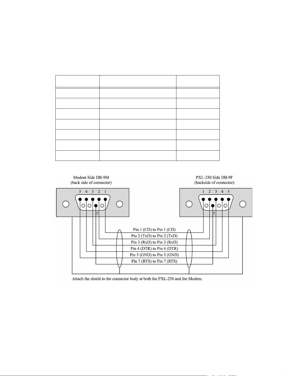
Technical Reference Manual – PXL-250 and SB-293 Keri Systems, Inc.
9.10.3.3 Modem/DB-9M to PC/DB-9F Cable Wiring
This is the wiring information for a cable that must be purchased or made by the
installer.
Table 21: Modem/DB-9M to PC/DB-9F Cable Wiring
Modem DB-9M RS-232 Standard Wire Color PC DB-9F
Pin 1 – CD Blue Pin 1 – CD
Pin 2 – TxD Green Pin 2 – TxD
Pin 3 – RxD Red Pin 3 – RxD
Pin 4 – DTR White Pin 4 – DTR
Pin 5 – GND Black Pin 5 – GND
Pin 7 – RTS Brown Pin 7 – RTS
Connector Body Shield Connector Body
Figure 9-21: Modem/DB-9M to PC/DB-9F Cable Wiring
Page 68 P/N: 01836-004 Revision 5.5
Page 69
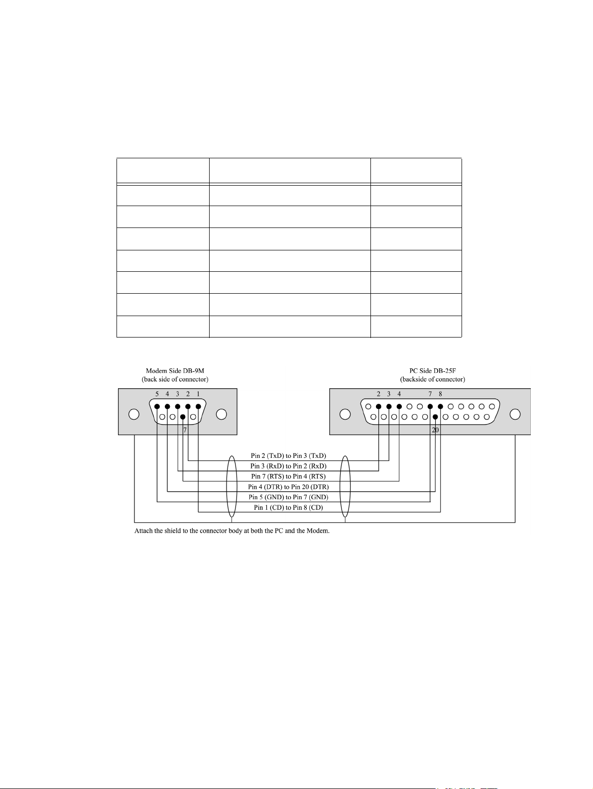
Keri Systems, Inc. Technical Reference Manual – PXL-250 and SB-293
9.10.3.4 Modem/DB-9M to PC/DB-25F Cable Wiring
This is the wiring information for a cable that must be purchased or made by the
installer.
Table 22: Modem/DB-9M to PC/DB-25F Cable Wiring
Modem DB-9M RS-232 Standard Wire Color PC DB-25F
Pin 1 – CD Blue Pin 8 – CD
Pin 2 – TxD Red Pin 3 – TxD
Pin 3 – RxD Green Pin 2 – RxD
Pin 4 – DTR White Pin 20 – DTR
Pin 5 – GND Black Pin 7 – GND
Pin 7 – RTS Brown Pin 4 – RTS
Connector Body Shield Connector Body
Figure 9-22: Modem/DB-9M to PC/DB-25F Cable Wiring
Revision 5.5 P/N: 01836-004 Page 69
Page 70

Technical Reference Manual – PXL-250 and SB-293 Keri Systems, Inc.
This page is intentionally left blank.
Page 70 P/N: 01836-004 Revision 5.5
Page 71
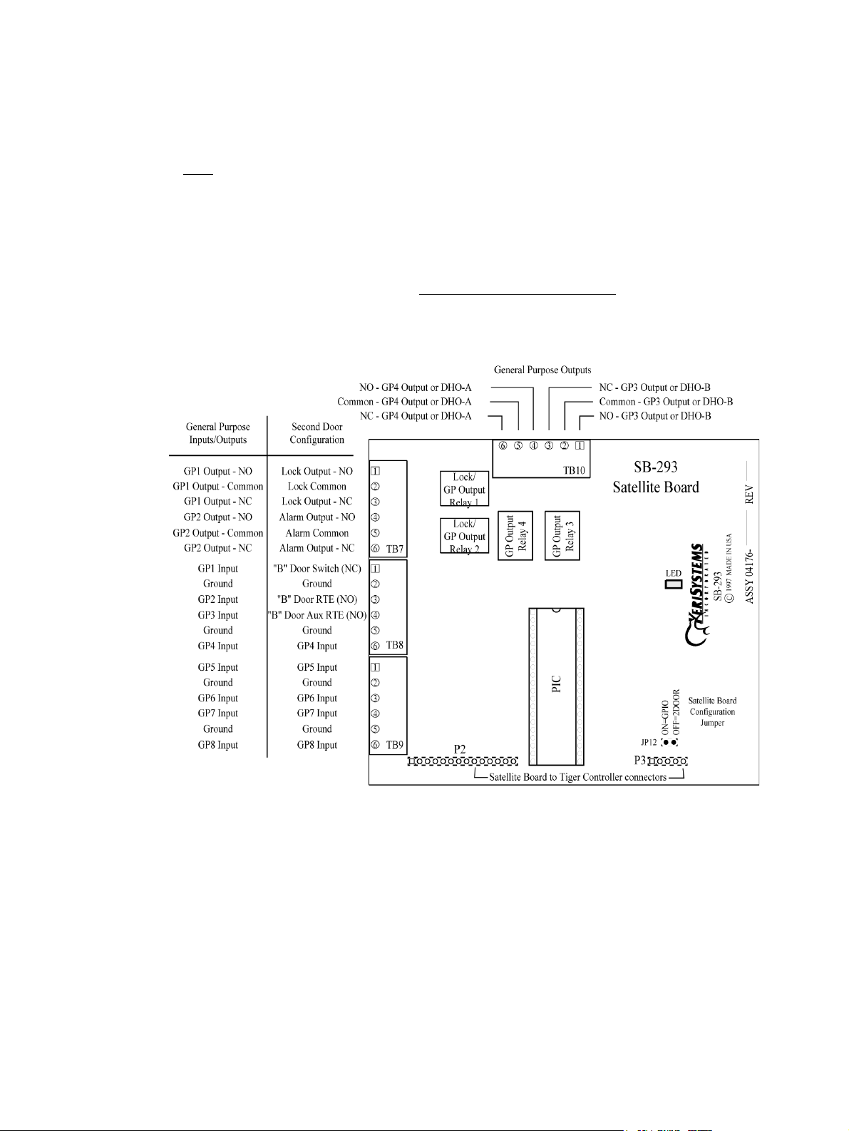
Keri Systems, Inc. Technical Reference Manual – PXL-250 and SB-293
10.0 Wiring Connections - SB-293
Before performing any wiring or connection operations, ensure that controller power
is OFF. Serious damage to sensitive components on the controller may occur if wiring
changes are made while controller power is on.
The following instructions assume that TB-10 is facing up (see Figure 10-1). With one
exception (the general-purpose relay outputs), all connections to the SB-293 satellite
board are made on the left side of the unit. Specific information for making each
wiring connection is provided in the Terminal Block Connections section on page 72.
Figure 10-1: The SB-293 Satellite Board
Revision 5.5 P/N: 01836-004 Page 71
Page 72
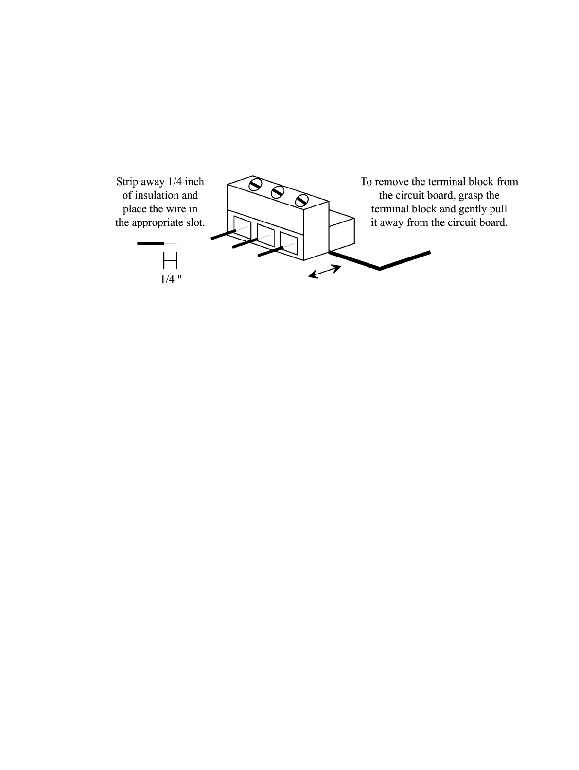
Technical Reference Manual – PXL-250 and SB-293 Keri Systems, Inc.
10.1 Terminal Block Connections
Follow these instructions as you make your wiring connections. Select the wire to be
installed. Strip away 1/4 inch of insulation from the wire, place the wire into the
appropriate slot on the terminal block, and tighten the corresponding screw on the top
of the terminal block (see Figure 10-2). Make a firm connection, but be careful not to
over tighten the screw.
Figure 10-2: Installing Wiring and Removing a Terminal Block
Please note that all of the terminal blocks slide off the SB-293 Satellite Board should it
become necessary to disconnect any installed cables. Firmly grasp the connector and
pull it away from the controller's printed circuit board (see Figure 10-2).
Page 72 P/N: 01836-004 Revision 5.5
Page 73
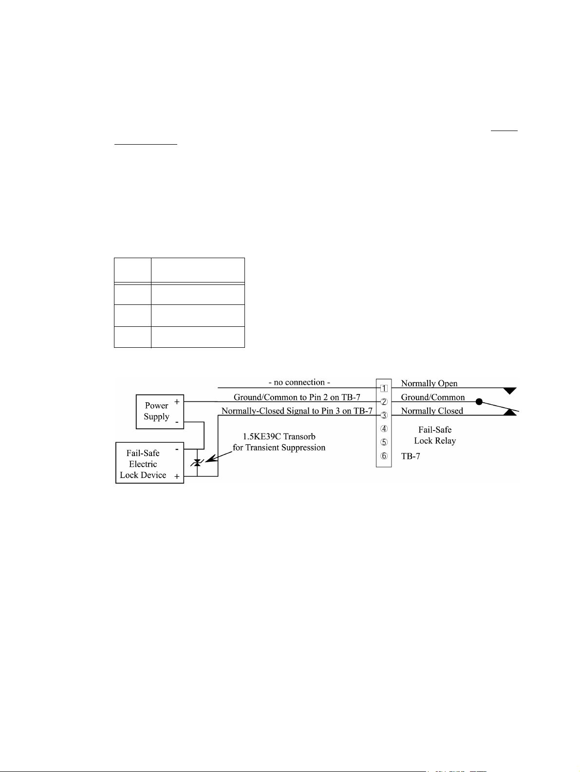
Keri Systems, Inc. Technical Reference Manual – PXL-250 and SB-293
10.2 Two-Door Configuration
10.2.1 TB-7 - Lock Relay Connection
The lock relay is a Form C relay used to control the door lock. Please refer to the Lock
Relay Output section starting on page 35 for more information on Lock relay outputs
and output devices.
For a typical fail-safe door lock relay installation, refer to Table 23 and Figure 10-3
and make the following wiring and transorb connections to attach the door lock relay.
Table 23: Lock Relay
Output Connections
TB-7 Description
Pin 1 Normally-Open
Pin 2 Common
Pin 3 Normally-Closed
Figure 10-3: Fail-Safe Lock Relay Output Connections
For a typical fail-secure door lock relay installation using a door strike, refer to Table
23 and Figure 10-4 on page 74 and make the following wiring and transorb
connections to attach the door lock relay.
Revision 5.5 P/N: 01836-004 Page 73
Page 74

Technical Reference Manual – PXL-250 and SB-293 Keri Systems, Inc.
Figure 10-4: Fail-Secure Lock Relay Output Connections
Page 74 P/N: 01836-004 Revision 5.5
Page 75

Keri Systems, Inc. Technical Reference Manual – PXL-250 and SB-293
10.2.2 TB-7 - Alarm Relay Connection
The Alarm Relay is a Form C relay that provides an output to trigger an audible signal
(or a silent alarm) whenever the door is put into an alarm state (i.e. the door is forced
open). It is also used to trigger an alarm signal whenever the door is held open too long
(exceeding the Open Time set within the Doors access control program). Depending
upon the type of alarm being installed and your application, your alarm may require a
normally closed/common connection, a normally open/common connection, or a
normally closed/common/normally open connection. Every application requires the
common lead connection. Refer to the Alarm Relay Output section starting on page 36
for more information on Alarm relay outputs and output devices.
The enhanced alarm out annunciation feature (configured in the Doors software) can
set this output to door forced annunciation for the B-door (door forced annunciation on
the A-door is handled by the alarm out relay on the PXL-250 controller). Door held
open alarm annunciation is connected to general-purpose output relays three and four
(see the TB10 - General Purpose Output Relay Connections section starting on
page 87).
For a typical alarm relay installation, refer to Table 24 and Figure 10-5 on page 76 and
make the following wiring and transorb connections to attach the alarm relay.
Table 24: Alarm Output
Relay Connections
TB-7 Description
Pin 4 Normally-Open
Pin 5 Common
Pin 6 Normally-Closed
Revision 5.5 P/N: 01836-004 Page 75
Page 76

Technical Reference Manual – PXL-250 and SB-293 Keri Systems, Inc.
Figure 10-5: Alarm Relay Output Connections
Page 76 P/N: 01836-004 Revision 5.5
Page 77

Keri Systems, Inc. Technical Reference Manual – PXL-250 and SB-293
10.2.3 TB-10 - Door Held Open Alarm Relay Connection
These instructions apply if the enhanced alarm out annunciation feature (in the Doors
software) has configured these outputs to door held open annunciation. Otherwise skip
to the TB10 - General Purpose Output Relay Connections section starting on page 87.
The Door Held Open Alarm Relay is a Form C relay that provides an output to trigger
an audible signal (or a silent alarm) whenever the door is put into an alarm state;
whenever the door is held open too long (exceeding the Open Time set within the
Doors access control program). General-purpose output four can be configured to be
the door held open alarm for the A-door on the PXL-250 controller. General-purpose
output 3 can be configured to be the door held open alarm for the B-door on the SB293 satellite board. Refer to the Door Held Open Alarm Relay output section on
page 36 for more information on alarm relay outputs and output devices.
For a typical door held open alarm relay installation for the A-door, refer to Table 25
and Figure 10-6, both on page 78, and make the following wiring and transorb
connections to attach the door held open alarm relay.
For a typical door held open alarm relay installation for the B-door, refer to Table 26
and Figure 10-7, both on page 79, and make the following wiring and transorb
connections to attach the door held open alarm relay.
Revision 5.5 P/N: 01836-004 Page 77
Page 78

Technical Reference Manual – PXL-250 and SB-293 Keri Systems, Inc.
Table 25: Door Held Open Alarm
Output Relay Connections
A-Door
TB-10 Description
Pin 4 Normally-Open – GPO 4
Pin 5 Common
Pin 6 Normally-Closed – GPO 4
Figure 10-6: Door Held Open Alarm Relay Output Connections – A-Door
Page 78 P/N: 01836-004 Revision 5.5
Page 79

Keri Systems, Inc. Technical Reference Manual – PXL-250 and SB-293
Table 26: Door Held Open Alarm
Output Relay Output Connections
B-Door
TB-10 Description
Pin 1 Normally-Open – GPO 3
Pin 2 Common
Pin 3 Normally-Closed – GPO 3
Figure 10-7: Door Held Open Alarm Relay Output Connections – B-Door
Revision 5.5 P/N: 01836-004 Page 79
Page 80

Technical Reference Manual – PXL-250 and SB-293 Keri Systems, Inc.
10.2.4 TB10 - General Purpose Output Relay Connections
If output relays three and four have not been configured for use for door held open
annunciation (as described in the previous section) they are available for generalpurpose use. General-Purpose Output Relays are Form C relays that provide an output
to enable or disable a device outside the controller. This device can be attached to the
relay's normally closed circuit so that the device is always on until the relay energizes
to open the circuit and turn it off. Or, this device can be attached to the relay's normally
open circuit so that the device is always off until the relay energizes to turn it on.
Depending upon the type of device being installed and your application, the device
may require a normally closed/common connection, a normally open/common
connection, or a normally closed/common/normally open connection. Every
application requires the common lead connection. Refer to the General-Purpose
Output Relay section on page 37 for more information on general-purpose relay
outputs and output devices.
For examples of typical general-purpose relay installations, refer to Table 27, and
Figures 10-8 and 10-9, both on page 81, and make the following wiring and transorb
connections.
Table 27: General-Purpose Output Relay
Connections – Two-Door Configuration
TB-10 Description
TB-10, Pin 1 Normally-Open – GPO 3
TB-10, Pin 2 Common
TB-10, Pin 3 Normally-Closed – GPO 3
TB-10, Pin 4 Normally-Open – GPO 4
TB-10, Pin 5 Common
TB-10, Pin 6 Normally-Closed – GPO 4
Page 80 P/N: 01836-004 Revision 5.5
Page 81

Keri Systems, Inc. Technical Reference Manual – PXL-250 and SB-293
Figure 10-8: Normally Open General Purpose Relay Output Connections - Two-Door
Configuration
Figure 10-9: Normally Closed General Purpose Relay Output Connections - TwoDoor Configuration
Revision 5.5 P/N: 01836-004 Page 81
Page 82
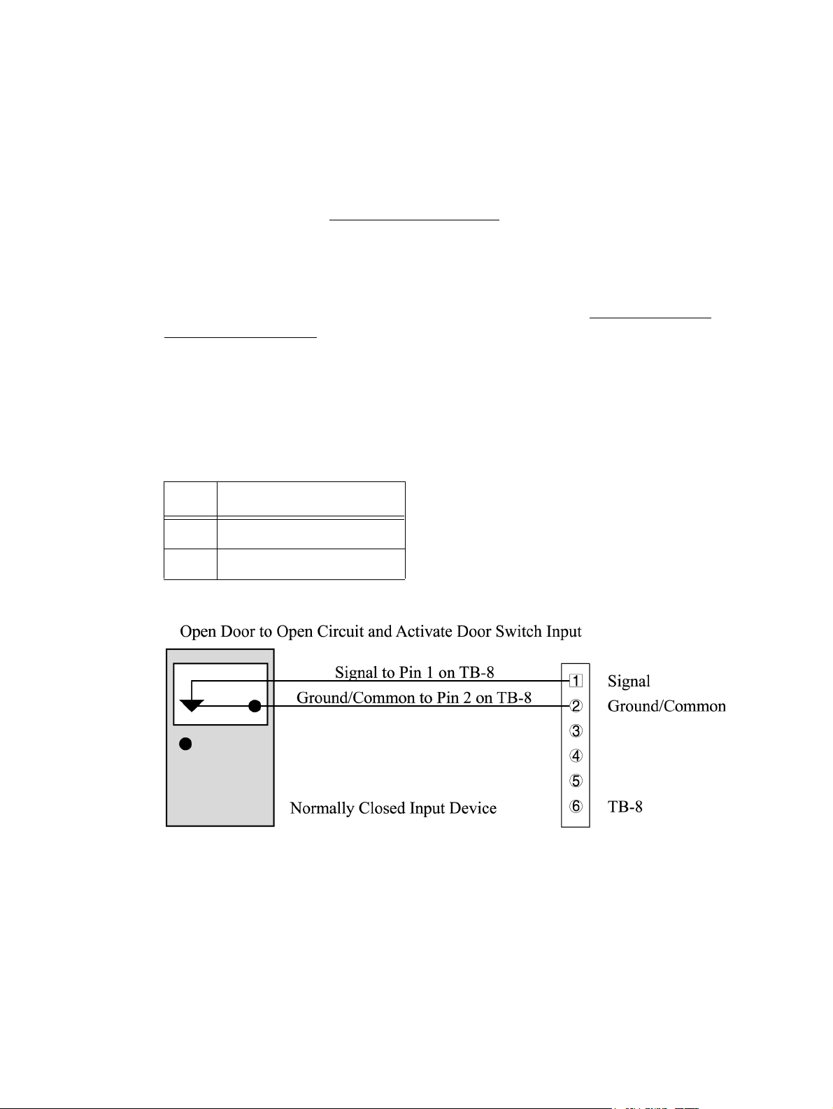
Technical Reference Manual – PXL-250 and SB-293 Keri Systems, Inc.
10.2.5 TB-8 - Door Status Switch Input Connection
The Door Status switch indicates the state of the door (open or closed). If a door status
switch is not being used, install a jumper between pins 1 and 2 of TB-8. The normal
state of this input is a closed circuit that will be opened when an input is generated. No
voltage is applied at this input; the circuit is opened and closed corresponding with the
door status. Refer to the Door Status Switch Input section on page 32 for more
information on Door Status Switch inputs and input devices.
NOTE: The SB-293 Satellite Board must have been configured for two door operation
for the door status switch input connections to be valid. If the SB-293 board has been
configured for general-purpose inputs and outputs, refer to the Additional Inputs/
Outputs Configuration section on page 87.
Refer to Table 28 and Figure 10-10 and make the following connections to attach a
door status input.
Table 28: Door Status Switch
Input Connections
TB-8 Description
Pin 1 Door Status Switch Input
Pin 2 Ground/Common
Figure 10-10: Door Status Switch Input Connections
NOTE: If a ground lead from the RTE input has already been installed on TB-8, pin 2,
loosen the terminal connector and insert the door status switch ground lead beside the
RTE input ground lead.
Page 82 P/N: 01836-004 Revision 5.5
Page 83
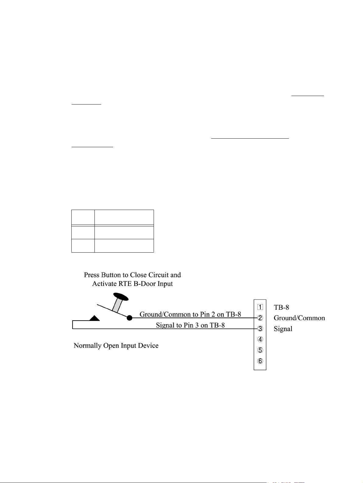
Keri Systems, Inc. Technical Reference Manual – PXL-250 and SB-293
10.2.6 TB-8 - Request to Exit Input Connection
Request to Exit (RTE - also known as REX) devices typically unlocks the door to
allow egress from the building. The SB-293 Satellite Board may accept input from
devices such as switches, motion sensors, or floor mats. The normal state of this input
is an open circuit that will be closed when an input is generated. No voltage is applied
at this input; the circuit is completed to indicate an RTE event. Refer to the Request to
Exit Input section on page 33 for more information on RTE inputs and input devices.
NOTE: The SB-293 Satellite Board must have been configured for two door operation
for the RTE input connections to be valid. If the SB-293 board has been configured for
general purpose inputs and outputs refer to the Additional Inputs/Outputs
Configuration section on page 87.
Refer to Table 29 and Figure 10-11 and make the following connections to attach an
RTE input.
Table 29: Request to Exit
Input Connections
TB-8 Description
Pin 2 Ground/Common
Pin 3 RTE Signal
Figure 10-11: Request to Exit Input Connections
NOTE: If a ground lead from the Door Status Switch input has already been installed
on TB-8, pin 2, loosen the terminal connector and insert the RTE ground lead beside
the door status input ground lead.
Revision 5.5 P/N: 01836-004 Page 83
Page 84
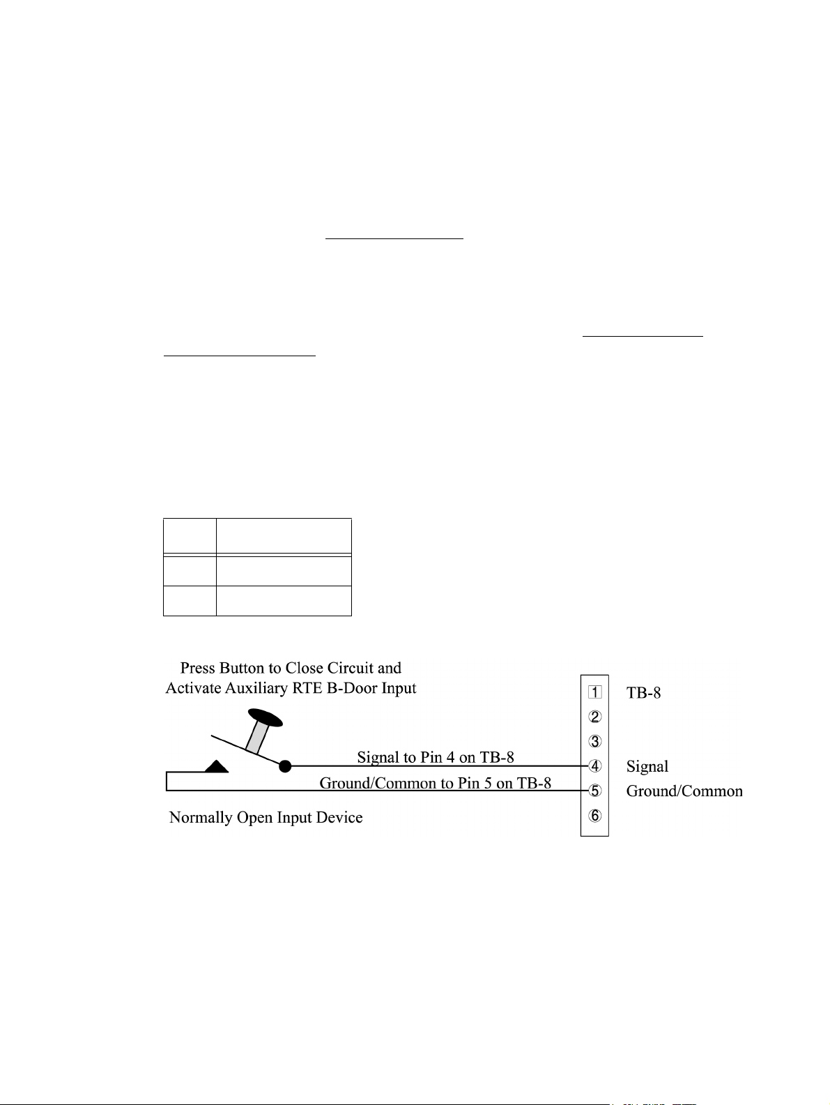
Technical Reference Manual – PXL-250 and SB-293 Keri Systems, Inc.
10.2.7 TB-8 - Auxiliary Request to Exit Input Connection
The Auxiliary Request to Exit (RTE - also known as REX) allows a secondary input
device to unlock the door to allow egress from the building. The SB-293 Satellite
Board may accept input from devices such as switches, motion sensors, or floor mats.
The normal state of this input is an open circuit that will be closed when an input is
generated. No voltage is applied at this input; the circuit is completed to indicate an
RTE event. Refer to the Auxiliary RTE Input section on page 33 for more information
on RTE inputs and input devices.
NOTE: The SB-293 Satellite Board must have been configured for two door operation
for the auxiliary RTE input connections to be valid. If the SB-293 board has been
configured for general purpose inputs and outputs refer to the Additional Inputs/
Outputs Configuration section on page 87.
Refer to Table 30 and Figure 10-12 and make the following connections to attach an
auxiliary RTE input.
Table 30: Auxiliary
Request to Exit Input
Connections
TB-8 Description
Pin 4 RTE Signal
Pin 5 Ground/Common
Figure 10-12: Auxiliary Request to Exit Input Connections
NOTE: If a ground lead from general-purpose input 4 has already been installed on
TB-8, pin 5, loosen the terminal connector and insert the auxiliary RTE ground lead
beside the general-purpose input ground lead.
Page 84 P/N: 01836-004 Revision 5.5
Page 85

Keri Systems, Inc. Technical Reference Manual – PXL-250 and SB-293
10.2.8 TB-8/TB-9 - General Purpose Input Connections
General-purpose inputs may be used in conjunction with the programmable input/
output feature of the Doors access control software. The normal state of these inputs
can be either a closed circuit that will be opened when an input is generated or an open
circuit that will be closed when an input is generated. No voltage is applied at these
inputs; the circuits are either opened or closed to indicate an input event. Refer to the
General Purpose Input section on page 34 for more information on general-purpose
inputs and input devices.
For examples of typical general purpose input connections, refer to Table 31 and
Figure 10-13 on page 86 and make the following connections.
Table 31: General Purpose Input Connections – Two-Door
Configuration
TB-8/TB-9 Description
TB-8, Pin 1 door status switch input - normally closed
TB-8, Pin 2 Common/Ground
TB-8, Pin 3 RTE input - normally open
TB-8, Pin 4
GPI 3 inputa/Aux RTE-Bb input - normally open
TB-8, Pin 5 Common/Ground
TB-8, Pin 6
TB-9, Pin 1
GPI 4 input
GPI 5 input
a
a
TB-9, Pin 2 Common/Ground
TB-9, Pin 3
TB-9, Pin 4
GPI 6 input
GPI 7 input
a
a
TB-9, Pin 5 Common/Ground
TB-9, Pin 6
a. General Purpose inputs can accept either a normally closed or
normally open signal. The type of signal depends upon the type of
input device. The
that type of input.
b. The Auxiliary RTE input feature is not available in 16-bit Doors
software applications.
GPI 8 input
a
Doors
software is then programmed to accept
Revision 5.5 P/N: 01836-004 Page 85
Page 86
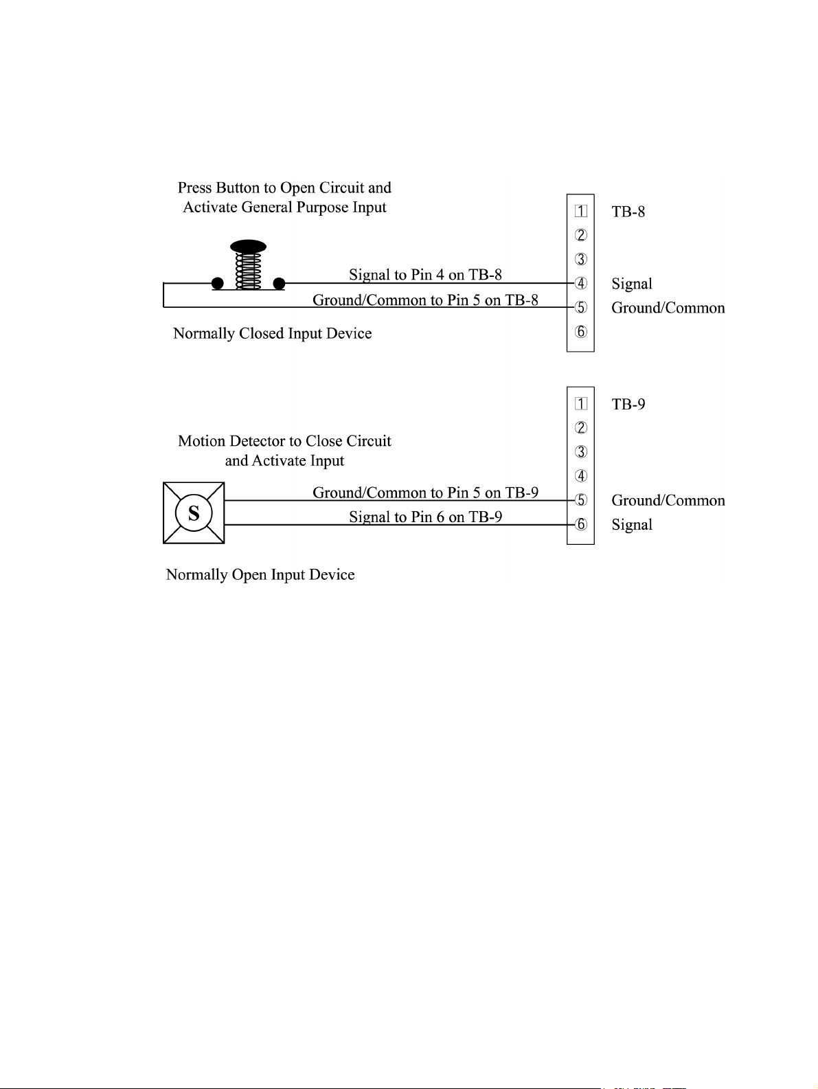
Technical Reference Manual – PXL-250 and SB-293 Keri Systems, Inc.
For the top application in Figure 10-13, a circuit is opened to create an input event at
the controller. For the lower application in Figure 10-13, the motion detector senses
motion and closes a circuit to create an input event at the controller.
Figure 10-13: General Purpose Input Connections - Two-Door Configuration
NOTE: Figure 10-13 provides examples of possible general purpose input connections
based on the information provided in Table 31 (on page 85). Make your input
connections in a similar manner to these, based on the pinouts given in Table 31.
Page 86 P/N: 01836-004 Revision 5.5
Page 87

Keri Systems, Inc. Technical Reference Manual – PXL-250 and SB-293
10.3 Additional Inputs/Outputs Configuration
10.3.1 TB-7/TB-10 - General Purpose Output Relay Connections
General Purpose Output Relays are Form C relays that provide an output to enable or
disable a device outside the controller. This device can be attached to the relay's
normally closed circuit so that the device is always on until the relay energizes to open
the circuit and turn it off. Or, this device can be attached to the relay's normally open
circuit so that the device is always off until the relay energizes to turn it on.
Depending upon the type of device being installed and your application, the device
may require a normally closed/common connection, a normally open/common
connection, or a normally closed/common/normally open connection. Every
application requires the common lead connection. Refer to the General-Purpose
Output Relay section on page 37 for more information on general-purpose relay
outputs and output devices.
For examples of typical general-purpose relay installations, refer to Table 32, and
Figures 10-14 and 10-15, both on page 88, and make the following wiring and transorb
connections.
Table 32: General-Purpose Output Relay Connections –
Additional I/O Configuration
TB-7/TB-10 Description
TB-7, Pin 1 Normally-Open – GPO 1
TB-7, Pin 2 Common
TB-7, Pin 3 Normally- Closed – GPO 1
TB-7, Pin 4 Normally-Open – GPO 2
TB-7, Pin 5 Common
TB-7, Pin 6 Normally-Closed – GPO 2
TB-10, Pin 1 Normally-Open – GPO 3
TB-10, Pin 2 Common
TB-10, Pin 3 Normally-Closed – GPO 3
TB-10, Pin 4 Normally-Open – GPO 4
TB-10, Pin 5 Common
TB-10, Pin 6 Normally-Closed GPO 4
Revision 5.5 P/N: 01836-004 Page 87
Page 88
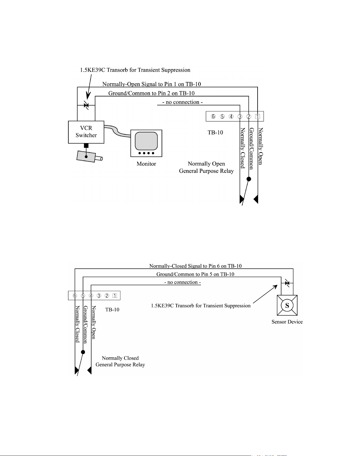
Technical Reference Manual – PXL-250 and SB-293 Keri Systems, Inc.
In the following application, an event causes programming in the controller to close
the normally-open line, temporarily activating a video camera.
Figure 10-14: Normally Open General Purpose Relay Output Connections - General
Purpose I/O Configuration
In the following application, an event causes programming in the controller to open
the normally-closed line, temporarily turning off a sensor device.
Figure 10-15: Normally Closed General Purpose Relay Output Connections - General
Purpose I/O Configuration
Page 88 P/N: 01836-004 Revision 5.5
Page 89

Keri Systems, Inc. Technical Reference Manual – PXL-250 and SB-293
10.3.2 TB-8/TB-9 - General Purpose Input Connection
General-purpose inputs may be used in conjunction with the programmable input/
output feature of the Doors access control software. The normal state of these inputs
can be either a closed circuit that will be opened when an input is generated or an open
circuit that will be closed when an input is generated. No voltage is applied at these
inputs; the circuits are either opened or closed to indicate an input event. Please refer
to the General Purpose Input section on page 34 for more information on generalpurpose inputs and input devices.
For examples of typical general purpose input connections, refer to Table 33 and
Figure 10-16 on page 90 and make the following connections.
Table 33: General-Purpose Input Connections –
Additional I/O Configuration
TB-8/TB-9 Description
TB-8, Pin 1
GPI 1 input
a
TB-8, Pin 2 Common/Ground
TB-8, Pin 3
TB-8, Pin 4
GPI 2 input
GPI 3 input
a
a
TB-8, Pin 5 Common/Ground
TB-8, Pin 6
TB-9, Pin 1
GPI 4 input
GPI 5 input
a
a
TB-9, Pin 2 Common/Ground
TB-9, Pin 3
TB-9, Pin 4
GPI 6 input
GPI 7 input
a
a
TB-9, Pin 5 Common/Ground
TB-9, Pin 6
a. General Purpose inputs can accept either a normally closed
or normally open signal. The type of signal depends upon
the type of input device. The
grammed to accept that type of input.
GPI 8 input
Doors
a
software is then pro-
Revision 5.5 P/N: 01836-004 Page 89
Page 90

Technical Reference Manual – PXL-250 and SB-293 Keri Systems, Inc.
For the upper application in Figure 10-16, a circuit is opened to create an input event at
the controller. For the lower application in Figure 10-16, the motion detector senses
motion and closes a circuit to create an input event at the controller.
Figure 10-16: General Purpose Input Connections - Additional I/O Configuration
Page 90 P/N: 01836-004 Revision 5.5
Page 91

Keri Systems, Inc. Technical Reference Manual – PXL-250 and SB-293
11.0 System Operation
11.1 Powering the System for the First Time
NOTE: Before turning the power on for the first time, please verify the earth ground1
has been connected at pin 3 on TB-2.
NOTE: Do not connect the 12 VDC Power Supply’s Terminal Block Output to the TB2 connector on the PXL-250 until you have completed all the steps in section 5.1.
When powering on the system for the first time, the installer should verify the 12 VDC
controller supply voltage and reset system RAM to ensure proper operation of the
PXL-250 controller.
11.1.1 Verify 12 VDC Supply Voltage
To verify the 12 VDC supply voltage:
1. Set the DVM to a DC volts scale capable of reading 12 VDC.
2. Turn the power supply ON.
3. Place the Red DVM lead on the power supply’s terminal block output - Pin 1.
4. Place the Black DVM lead on the power supply’s terminal block output - Pin 2.
5. Check the DVM reading. It should read between +12 VDC to +14 VDC.
6. If the DVM does not read between +12 VDC to +14 VDC, verify the power supply
is of the correct voltage, verify the cable length does not exceed 200 feet, and
verify the cable gauge is AWG 18. This problem must be corrected before power
can be supplied to the controller.
7. Turn the power supply OFF.
8. Connect the power supply’s terminal block output to the TB-2 connector on the
PXL-250 controller.
9. The controller is now ready to be powered ON.
NOTE: On long power cable runs, keep in mind the resistance in the cable itself
causes a drop in voltage at the end of the run. The power supply must be able to
account for this voltage drop.
1. Ground wire is green with yellow tracer.
Revision 5.5 P/N: 01836-004 Page 91
Page 92

Technical Reference Manual – PXL-250 and SB-293 Keri Systems, Inc.
11.1.2 Verify Wiegand Compatible Reader Supply Voltage
All Keri Systems proximity readers use 5 to 12 VDC power (except for the MS-9000
which uses 12 to 24 VDC power) while most Wiegand compatible readers use just 5
VDC power. For Wiegand configured PXL-250 controllers, there is a warning LED on
the controller board to indicate if the controller is applying 12 VDC to the Wiegand
compatible reader (see Figure 11-1). If your Wiegand compatible reader does operate
on 5 VDC no changes need to be made, the default position for the jumper is to set
power to 5 VDC. If your Wiegand compatible reader requires 12 VDC, turn the
controller power off and follow the instructions in the Jumper Settings section on
page 28 to set the reader supply voltage to 12 VDC. When power is restored, the
warning LED will turn on indicating 12 VDC is being supplied to the Wiegand
compatible reader.
Figure 11-1: Wiegand 12 VDC Warning LED
NOTE: Applying 5 VDC to a 12 VDC reader will not damage the 12 VDC reader.
However, applying 12 VDC to a 5 VDC reader very likely will damage the 5 VDC
reader. Be sure you are applying the correct supply voltage to the reader. Keri Systems
cannot be responsible for 5 VDC readers damaged by excessive voltage.
11.1.3 Resetting the Controller's RAM
If you're turning system power on for the first time, the PXL-250 controller's RAM
must be reset before performing any other action. This clears any spurious information
that may be in the RAM in preparation for entering your access control information.
On the controller, insert a jumper across pins 1 and 2 of JP3. Hold the S1 Address and
Diagnostics Button down and turn the controller's power on (see Figure 9-1 on page 39
and Figure 11-2 on page 93). The beeper for the reader attached to the controller will
beep as power comes on followed by a beep-beep indicating the controller's firmware
has reset the controller's RAM. Release S1. If the optional Alpha/Numeric Plug-in
Display has been installed, it will display a "SYSTEM RESET" message. Remove the
jumper on JP-3. The controller is now ready for programming.
Page 92 P/N: 01836-004 Revision 5.5
Page 93

Keri Systems, Inc. Technical Reference Manual – PXL-250 and SB-293
Figure 11-2: Close-Up of JP-3, S1, and Address Display LEDs
NOTE: Resetting the system RAM completely erases all information within the PXL250 controller. Should there be any information in system RAM from an access control
installation and the system RAM is reset, the information in the controller is lost and
cannot be recovered from the controller.
11.1.4 Controllers with Modems
If the controller is a master controller and it communicates with the host
computer via modem, power up the modem before powering up the controller.
This ensures the modem is ready and able to communicate with the controller
when the controller becomes ready to determine the method of communication
with the host computer. While most modems initialize quickly and can respond to
the controller’s inquiry, some take more time and result in the controller not
recognizing the modem and configuring itself for communication with the host
computer via a direct-connect serial cable.
Revision 5.5 P/N: 01836-004 Page 93
Page 94

Technical Reference Manual – PXL-250 and SB-293 Keri Systems, Inc.
11.2 Normal Operation
For normal operation, turn the system power on. The power LED should be on. On the
master controller the network LED should be blinking, indicating it is communicating
with other PXL-250 controllers on the network. If this is a single controller network,
the LED will blink for several minutes until it determines that there are no other
controllers with which to communicate, then it will turn off. The address programmed
into the controller will flash on the address display LEDs for 2 seconds.
If the optional Alpha/Numeric Plug-in Display has been installed, it will display a Keri
Systems header and the controller's address (see Figure 11-3).
Figure 11-3: PXL-250 Controller Standard Operation Message
11.3 Viewing Controller Addresses
To view a controller's address, click S1 (see Figure 9-1 on page 39 and Figure 11-2 on
page 93). The controller's address appears on the address display for 2 to 3 seconds.
11.4 Setting Controller Addresses
To set the desired operating address for the controller, turn the controller's power off.
Verify JP3 is not installed (see Figure 9-1 on page 39 and Figure 11-2 on page 93 – if
JP3 is installed, the controller RAM will be reset when the power is turned on). Hold
the S1 Address and Diagnostics Button down and turn the controller's power on. The
beeper for the reader attached to the controller will beep as power comes on followed
by a beep-beep indicating the controller's firmware has entered the address setting
mode. Release S1. The address display LEDs then become active and the controller's
address can be set. If an Alpha/Numeric Display (LCD-1) is connected to the
controller, "Address Change" will appear on the display. The address range is from 1
to 128 (the Master Controller must always be set to address 1).
Page 94 P/N: 01836-004 Revision 5.5
Page 95

Keri Systems, Inc. Technical Reference Manual – PXL-250 and SB-293
Quickly double clicking S1 toggles between increasing and decreasing the controller
address. The top LED character will display either a "+" or a "-" to show which
direction is active. A single click of S1 changes the controller address by 1. If you're at
address 128, a +1 click will roll the address over to 1; conversely, if you're at address 1
a -1 click will roll the address over to 128. Holding S1 down rapidly scrolls through
the addresses. Click through the address range until the desired address is displayed by
the address display LEDs.
After the new address has been set, you must wait approximately 30 seconds. There is
a timer in the controller's firmware that assumes that after 30 seconds of inactivity (no
address clicks), the entered address is the desired address for that controller. When the
30-second timer expires, there will be a beep-beep (from the “A-Door” reader attached
to the controller) indicating the controller has recognized and accepted the new
address and the address LEDs will turn off. If an Alpha/Numeric Display (LCD-1) is
connected to the controller, "UNIT ##" will appear on the display (where ## is the
controller's address - see Figure 11-3 on page 94).
11.5 Master Controller Requirements
The master controller must be set to address 1 so that all slave controllers on the access
control network can identify the master controller. For the master controller to
correctly identify all slave controllers on the network, the Auto-Configuration routine
within the Doors program must be run. This instructs the master controller to poll all
other controllers on the network for addresses and configuration information (the
Auto-Configuration button is found under the Setup/System/controllers tab in the
Doors program).
Revision 5.5 P/N: 01836-004 Page 95
Page 96

Technical Reference Manual – PXL-250 and SB-293 Keri Systems, Inc.
11.6 Proximity Reader Responses to Access Control Events
During day-to-day activity, a proximity reader will respond to access control events in
a specific manner. Refer to Table 34 for a summary of the reader's LED and beeper
actions during access control events.
Table 34: Proximity Reader Responses to Access Control Events
Event Reader’s LED Status Reader’s Beeper Status
waiting for
an event
access
granted
access
denied
door alarm flashing Red LED for the duration
door RTE displays a Green LED until the
displays a steady Amber LED silent
displays a Green LED until the
door is closed or the door unlock
time is reached
flashes a Red LED one short Beep
of the alarm condition
door is opened or the door unlock
time is reached
11.7 I/O Configuration
All I/O configuration functions are handled within the Doors access control program.
For specific information, please refer to the Doors User's Guide (P/N 01821-002) or to
the on-line help information found within the Doors program.
one long Beep
pulsating Beep for the duration of the alarm condition
one long Beep
Page 96 P/N: 01836-004 Revision 5.5
Page 97
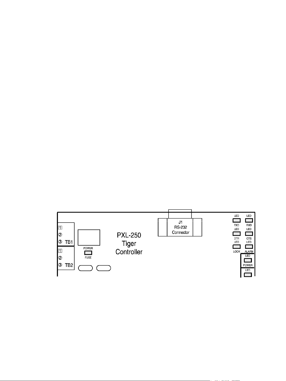
Keri Systems, Inc. Technical Reference Manual – PXL-250 and SB-293
12.0 Periodic Maintenance
To ensure the best operating conditions for your access control system, Keri Systems
recommends performing the following checks periodically at each controller.
1. Verify the controller's earth ground is still a quality earth ground.
2. Verify all terminal block connections continue to be secure.
3. Perform the signal strength test found in the Troubleshooting and Diagnostics
Appendix to ensure that reader signal quality at the controller is maintained and
that reader read range continues to be high.
4. If the controller has a backup battery for operation during a power outage,
disconnect the power and verify the controller continues to operate under backup
battery power.
If there are any concerns regarding the operation or performance of the PXL-250
Controller or SB-293 Satellite board, please review the Troubleshooting and
Diagnostics Appendix.
A number of status LEDs have been placed on the controller PCB to help maintain the
controller and verify controller operation. Please refer to Figure 9-1 on page 39 and
Figure 12-1 for the location of these LEDs.
• Communication LEDs
• Power LEDs
• Lock and Alarm LEDs
Figure 12-1: Modem/Controller Communication LEDs
Revision 5.5 P/N: 01836-004 Page 97
Page 98

Technical Reference Manual – PXL-250 and SB-293 Keri Systems, Inc.
12.1 Communication LEDs
To help monitor controller/modem communication and to help troubleshoot modem
communication issues, a set of LEDs have been added to the upper-right corner of the
controller board (see Figure 9-1 on page 39 and Figure 12-1).
These LEDs flicker, corresponding to the state of the following lines.
• TXD – Transmit Data
• RXD – Receive Data
• DTR – Data Terminal Ready
• CTS – Clear To Send
By noting the operation being performed by the controller and monitoring the LED
states, you are able to determine if data transmission between modem and controller is
being performed.
12.2 Power LEDs
Two LEDs are used to monitor the status of the power being supplied to the controller.
• Fuse LED
• Power/Voltage LED
12.2.1 Fuse LED
The Fuse LED (at the left side of the controller) is attached to a power monitoring
circuit protecting the 12 VDC power connection. The fuse circuit monitors power
polarity and power quality. This is a thermal fuse; if there is a power problem, the fuse
overheats and opens, removing power from the controller, protecting it from damage.
After a period of time the fuse cools off, reconnecting the power circuit. In standard
operation, the Fuse LED is off.
• If the LED is red, the fuse is open because the power and ground lines are
reversed. Turn controller power off and verify the polarity of the power coming to
the controller.
• If the LED is green, the controller’s fuse has opened because there is a power
problem, protecting the controller. This controller should be serviced as soon as
possible.
Page 98 P/N: 01836-004 Revision 5.5
Page 99

Keri Systems, Inc. Technical Reference Manual – PXL-250 and SB-293
12.2.2 Power/Voltage LED
The Power/Voltage LED (at the right side of the controller) is attached to a circuit that
monitors the voltage level received by the controller. In standard operation this LED is
green (meaning the power being provided to the controller meets the controller’s
power specifications.
If the LED is red, this means an under or over voltage condition exists that can affect
the operation of the controller. When an under or over voltage condition is detected,
the address display (see Figure 9-1 on page 39 and Figure 11-2 on page 93) shows the
voltage value detected by the controller. With a DVM, verify this voltage and make
corrections to the voltage source as necessary to bring the controller voltage back to 12
VDC.
12.3 Lock and Alarm LEDs
The Lock and Alarm LEDs reflect the status of the Lock and Alarm relays. When
these relays are not energized (their normal state) the LEDs are off.
When a door is unlocked (whether through a card presentation or manual operation),
the Lock LED turns green and stays green until the door is locked again.
When a door goes into an alarm state, the Alarm LED turns green and stays green for
the duration of the alarm state.
Revision 5.5 P/N: 01836-004 Page 99
Page 100

Technical Reference Manual – PXL-250 and SB-293 Keri Systems, Inc.
This page is intentionally left blank.
Page 100 P/N: 01836-004 Revision 5.5
 Loading...