

Page 1
SB-293 Satellite Board
This quick start guide is made up of a specification sheet, basic installation drawings and information, and short
descriptions of key terms and concepts. For comprehensive information regarding the SB-293 Satellite Board, please
refer to the Technical Reference Manual (P/N 01836-004).
1.0 Specifications
Unit Dimensions
• PXL-250 controller PCB with an SB-293 Satellite Board
- 7.25 inches high by 6.00 inches wide by 1.75 inches deep, including wiring connectors
- (18.45 cm by 15.25 cm by 4.45 cm)
• PXL-250 controller PCB with an SB-293 Satellite Board and an LCD-1 Alpha/Numeric Display
- 8.10 inches high by 6.00 inches wide by 1.75 inches deep, including wiring connectors
- (20.60 cm by 15.25 cm by 4.45 cm)
•Enclosure
- 9.70 inches high by 8.20 inches wide by 2.60 inches deep
- (24.65 cm by 20.85 cm by 6.60 cm)
Operating Temperature/Humidity Range
• 0°F to 140°F (-18°C to 60°C)
• 0% to 90% Relative Humidity, non-condensing
Controller with Satellite Board Power Requirements
• 12 VDC @ 1 Amp
Current Draw
• maximum current draw 270 mA for a controller plus reader current draw (refer to Table 1 for Reader current draw)
• 120 mA max for a PXL-250 Controller
• 150 mA max for an SB-293 Satellite Board
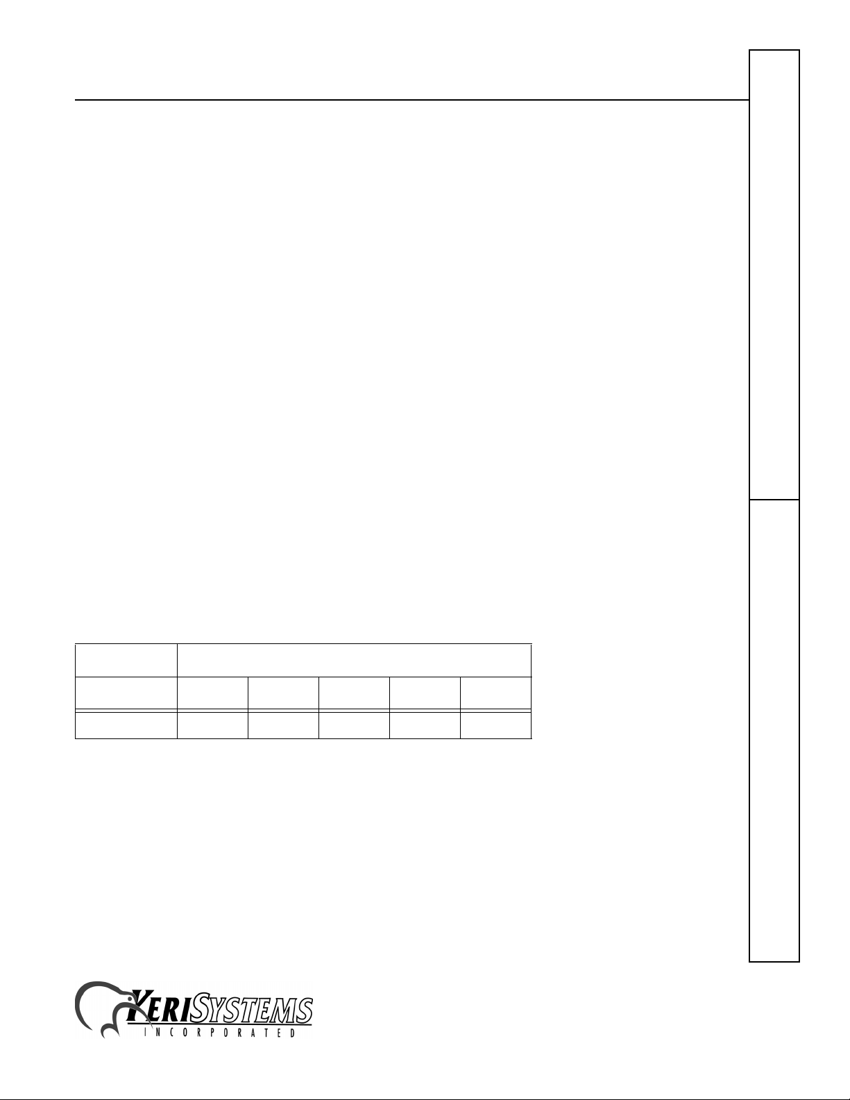
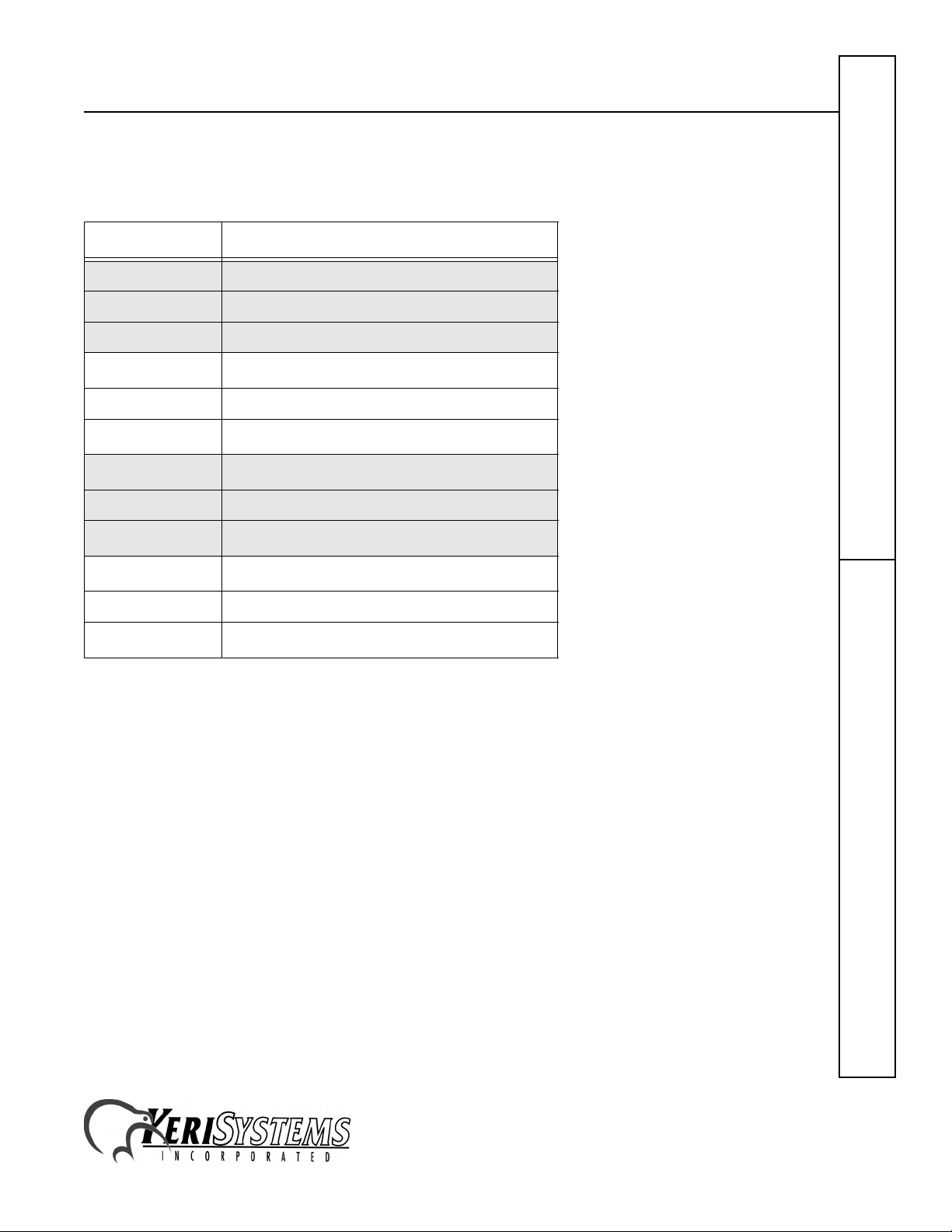
Table 1: Reader Current Draw
Reader Type
MS-3000 MS-4000 MS-5000 MS-7000 MS-9000
Current Draw
Output Relay Contact Rating
• 1 Amp @ 24 VDC
Input Device Configuration
• Door Sense normally closed
• Request to Exit normally open
• Global Unlock normally open, or
Auxiliary RTE A-Door normally open
50 mA 50 mA 100 mA 200 mA 200 mA
SB-293Quick Start Guide
1530 Old Oakland Road, Suite 100 01837-003 Rev. 2.3
San Jose, CA 95112 USA
(800) 260-5265 (408) 451-2520 FAX (408) 441-0309
Web: http://www.kerisys.com E-mail: sales@kerisys.com Page 1 of 16
Page 2

SB-293 Satellite Board
2.0 Cable Requirements
• two conductor, stranded, AWG 22 or a larger gauge for all input/output connections
NOTE: The Lock Output relay may require a heavier gauge of wire depending upon the current demands of the lock and
the length of the lock wiring run.
3.0 When Installing Satellite Boards
DO
• route cables in accessible areas for ease of maintenance
• add transient suppression across electric devices attached to a satellite board output
• use an isolation relay (Keri Systems P/N IRP-1) if attaching to a parking gate, a turnstile, or any application using a
large electric motor
• for a single door application, install the door's reader to the TB-5, "A" reader connection on the controller
• for a two door application, install the primary door's reader to the TB-5, "A" reader connection on the controller
and install the secondary door's reader to the TB-6, "B" reader connection on the controller
DO NOT
• stretch or over-tension cables
Quick Start GuideSB-293
• route cables over sharp objects
• let cables or wires get tangled
4.0 Jumper Setting
JP12 - Configures the Satellite Board (see Figure 1)
• Jumper across JP12, pins 1 and 2, configures the Satellite board for general purpose inputs and outputs.
• NO jumper across JP12 configures the Satellite board for second door control with additional inputs and outputs.
When the Satellite board is configured for second door control, the primary door must be connected to the "A"
reader (TB-5 on the PXL-250 controller board) and the secondary door must be connected to the "B" reader (TB-6
on the controller board).
Figure 1: Setting JP12
1530 Old Oakland Road, Suite 100 01837-003 Rev. 2.3
San Jose, CA 95112 USA
(800) 260-5265 (408) 451-2520 FAX (408) 441-0309
Web: http://www.kerisys.com E-mail: sales@kerisys.com Page 2 of 16
Page 3
SB-293 Satellite Board
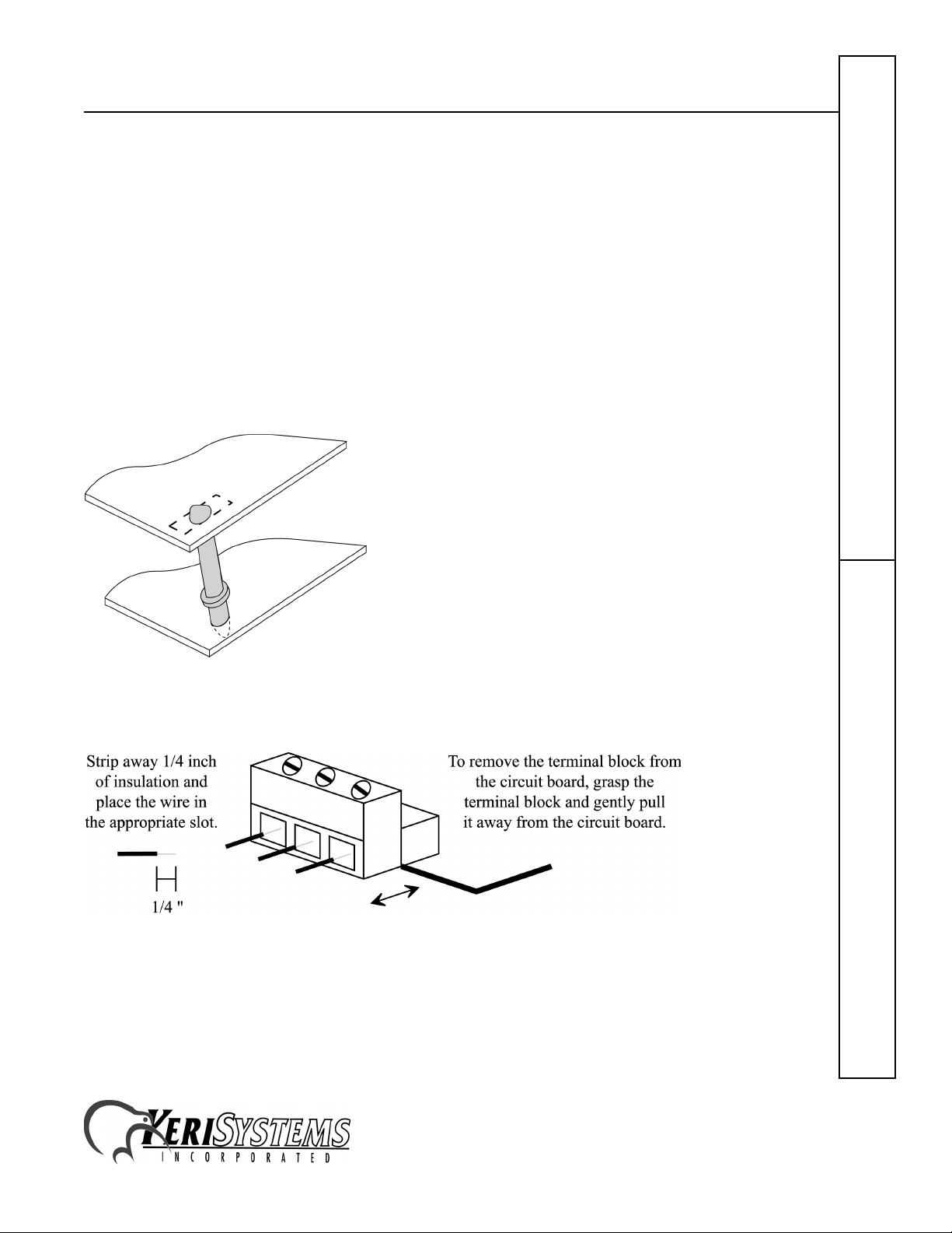
5.0 Board Installation
Perform the following steps to install an SB-293 Satellite board on a PXL-250 controller (see Figure 2).
1. Turn the controller's power OFF.
2. Line up the upper left-hand corner of the Satellite PCB with the controller PCB.
3. Line up the stand-offs in the top two corners of the Satellite PCB with corresponding mounting holes in the
controller PCB (see Figure 2).
4. Align the Satellite Board to Motherboard connector pins (J2 and J3).
5. Gently press the two boards together with each stand-off into its mounting hole and with the connector pins
meshing together.
6. Turn the controller’s power ON.
If the J2 to P2 connector pins have been meshed together properly the LED on the SB-293 turns green (see Figure 4 on
page 4).
Figure 2: Stand-off Installation
6.0 Connecting Wires - Removing a Terminal Block
Figure 3: Connecting Wires to Terminal Blocks
1530 Old Oakland Road, Suite 100 01837-003 Rev. 2.3
San Jose, CA 95112 USA
(800) 260-5265 (408) 451-2520 FAX (408) 441-0309
Web: http://www.kerisys.com E-mail: sales@kerisys.com Page 3 of 16
SB-293Quick Start Guide
Page 4
SB-293 Satellite Board
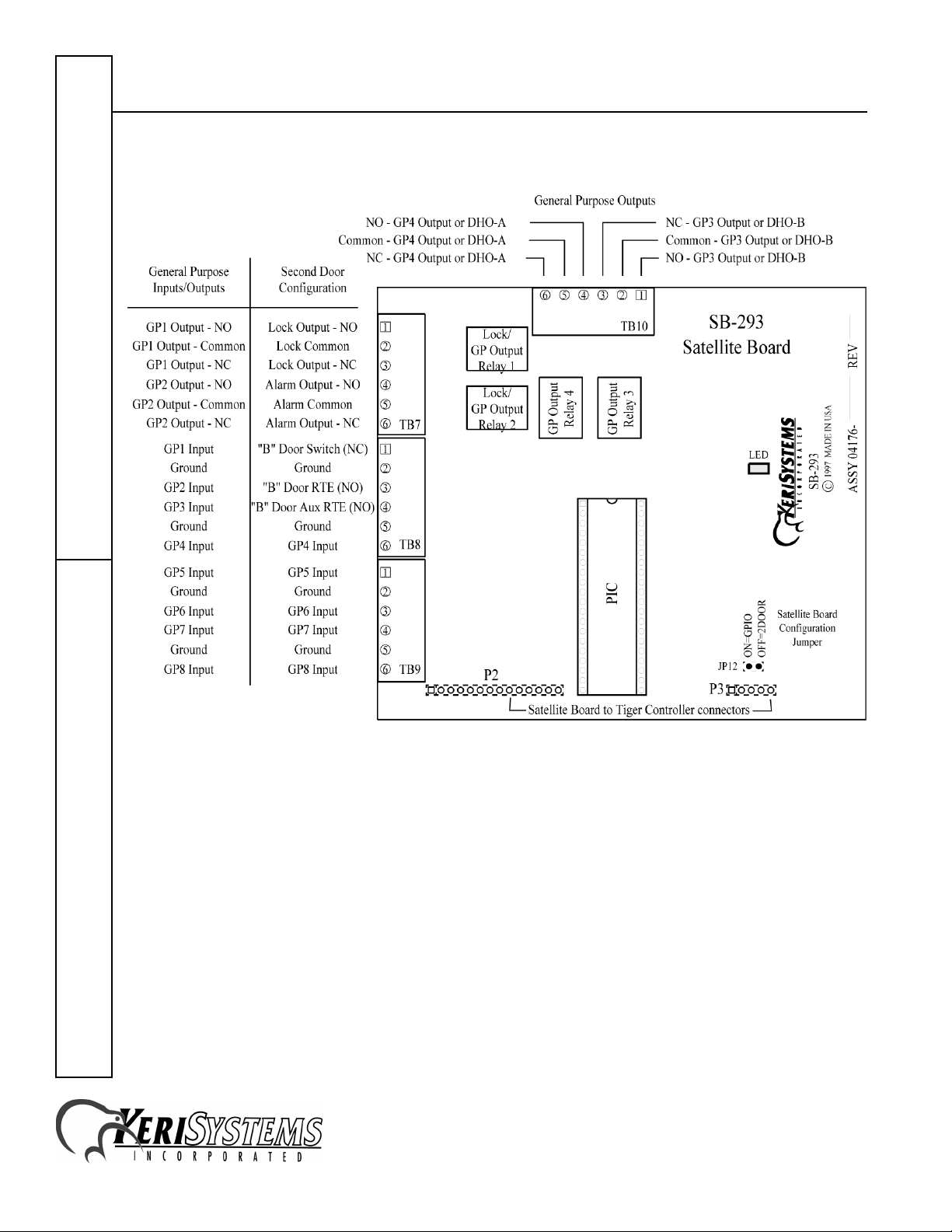
7.0 The SB-293 Satellite Board Wiring Connections
Quick Start GuideSB-293
Figure 4: The SB-293 Satellite Board
1530 Old Oakland Road, Suite 100 01837-003 Rev. 2.3
San Jose, CA 95112 USA
(800) 260-5265 (408) 451-2520 FAX (408) 441-0309
Web: http://www.kerisys.com E-mail: sales@kerisys.com Page 4 of 16
Page 5

SB-293 Satellite Board
7.1 Two Door Configuration Connections
This configuration assumes JP12 is
7.1.1 Output Relays
Please refer to Figure 4 on page 4 for output relay wiring locations.
Table 2: Output Relays
TB-7/TB-10 Relay Outputs Description
TB-7 – Pin 1 lock output – normally open line
TB-7 – Pin 2 common/ground
TB-7 – Pin 3 lock output – normally closed line
TB-7 – Pin 4 alarm output – normally open line
TB-7 – Pin 5 common/ground
TB-7 – Pin 6 alarm output – normally closed line
OFF
, configuring the Satellite board for Two-Door control.
TB-10 – Pin 1
TB-10 – Pin 2 common/ground
TB-10 – Pin 3
TB-10 – Pin 4
TB-10 – Pin 5 common/ground
TB-10 – Pin 6
a. The Door Held Open (DHO) alarm feature is not available in
Doors
16-bit
See page 6 for a sample Fail-Safe Door Lock Output Relay drawing.
See page 6 for a sample Fail-Secure Door Lock Output Relay drawing.
See page 6 for a sample Alarm Output Relay drawing.
See page 7 for a sample Door Held Open – A-Door Relay drawing.
See page 7 for a sample Door Held Open – B-Door Relay drawing.
See page 8 for a sample General Purpose Normally-Open Output Relay drawing.
See page 8 for a sample General Purpose Normally-Closed Output Relay drawing.
software applications.
GPO 3/DHO-Ba – normally open line
GPO 3/DHO-Ba – normally closed line
GPO 4/DHO-A
GPO 4/DHO-A
a
– normally open line
a
– normally closed line
SB-293Quick Start Guide
1530 Old Oakland Road, Suite 100 01837-003 Rev. 2.3
San Jose, CA 95112 USA
(800) 260-5265 (408) 451-2520 FAX (408) 441-0309
Web: http://www.kerisys.com E-mail: sales@kerisys.com Page 5 of 16
Page 6
SB-293 Satellite Board
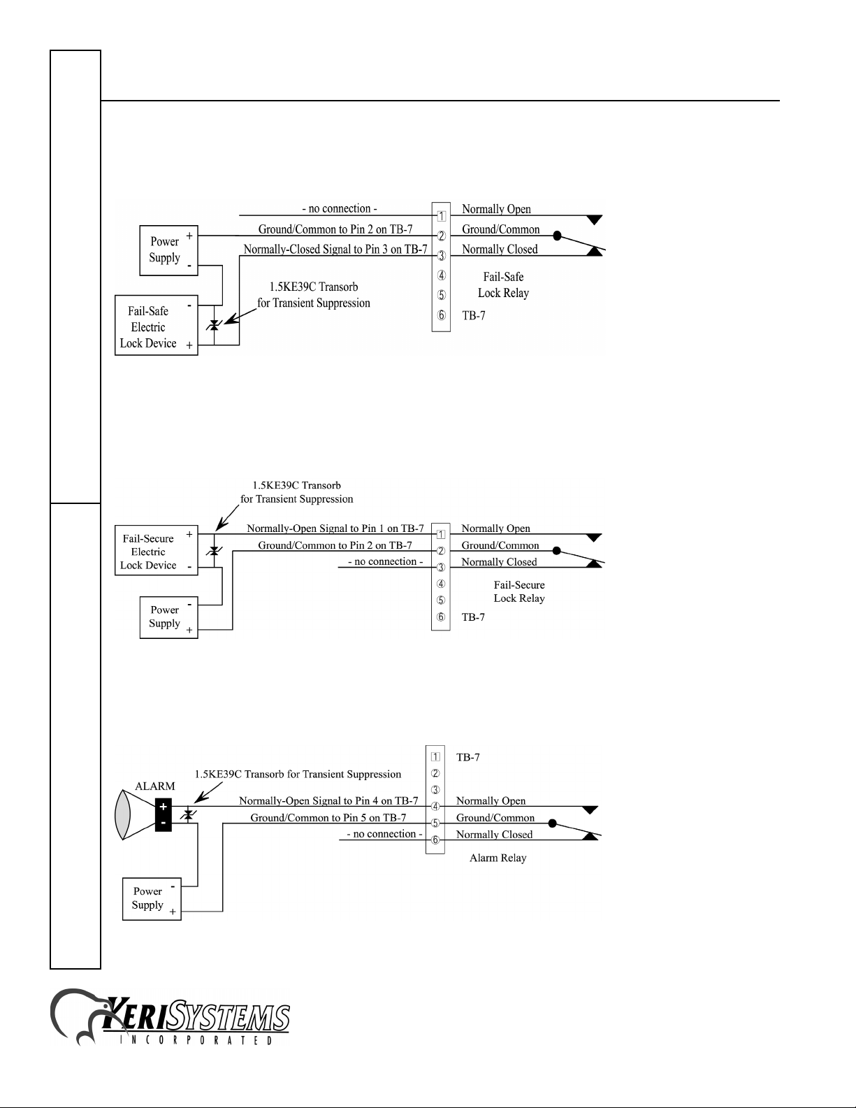
7.1.1.1 Fail-Safe Door Lock Output Relay
In a fail-safe application, if the power fails, the door is unlocked (see page 16 for information about fail-safe lock
applications).
Figure 5: Fail-Safe Door Lock Output Relay
7.1.1.2 Fail-Secure Door Lock Output Relay
In a fail-secure application, if the power fails, the door is locked (see page 16 for information about fail-secure lock
applications).
Quick Start GuideSB-293
Figure 6: Fail-Secure Door Lock Output Relay
7.1.1.3 Alarm Output Relay
An alarm condition on the controller closes the normally open line, sounding an alarm.
Figure 7: Alarm Output Relay
1530 Old Oakland Road, Suite 100 01837-003 Rev. 2.3
San Jose, CA 95112 USA
(800) 260-5265 (408) 451-2520 FAX (408) 441-0309
Web: http://www.kerisys.com E-mail: sales@kerisys.com Page 6 of 16
Page 7

SB-293 Satellite Board
7.1.1.4 Door Held Open Alarm Output Relay
These instructions apply if the enhanced alarm out annunciation feature in the
outputs for door held open annunciation. The DHO alarm feature is not available in 16-bit
If you are not using the DHO feature, skip to the General-Purpose Outputs sections on page 8.
An alarm condition on the controller closes the normally open line, sounding an alarm. The following figure is for the
A-door.
Doors
software has configured these
Doors
software applications.
Figure 8: Door Held Open Alarm – A-Door
The following figure is for the B-door.
Figure 9: Door Held Open Alarm – B-Door
SB-293Quick Start Guide
1530 Old Oakland Road, Suite 100 01837-003 Rev. 2.3
San Jose, CA 95112 USA
(800) 260-5265 (408) 451-2520 FAX (408) 441-0309
Web: http://www.kerisys.com E-mail: sales@kerisys.com Page 7 of 16
Page 8

SB-293 Satellite Board
7.1.1.5 General Purpose Outputs - Normally Open Relay Connection
In the following application, an event causes programming in the controller to close the normally-open line, temporarily
turning on a video camera.
Quick Start GuideSB-293
Figure 10: General Purpose Output – Normally Open Relay
7.1.1.6 General Purpose Outputs - Normally Closed Relay Connection
In the following application, an event causes programming in the controller to open the normally-closed line,
temporarily turning off a sensor device.
Figure 11: General Purpose Output – Normally Closed Relay
1530 Old Oakland Road, Suite 100 01837-003 Rev. 2.3
San Jose, CA 95112 USA
(800) 260-5265 (408) 451-2520 FAX (408) 441-0309
Web: http://www.kerisys.com E-mail: sales@kerisys.com Page 8 of 16
Page 9
SB-293 Satellite Board
7.1.2 Inputs Table
Please refer to Figure 4 on page 4 for output relay wiring locations.
Tabl e 3: I n put s
TB-8/TB-9 Inputs Description
TB-8 – Pin 1 door status switch input – normally closed
TB-8 – Pin 2 common/ground
TB-8 – Pin 3 RTE input – normally open
TB-8 – Pin 4
TB-8 – Pin 5 common/ground
TB-8 – Pin 6
TB-9 – Pin 1
TB-9 – Pin 2 common/ground
TB-9 – Pin 3
TB-9 – Pin 4
TB-9 – Pin 5 common/ground
TB-9 – Pin 6
a. General Purpose inputs can accept either a normally closed or
normally open signal. The type of signal depends upon the type
of input device. The
accept that type of input.
b. The Auxiliary RTE input feature is not available in 16-bit
software applications.
GPI 3 input
a
/ AUX RTE-Bb input – normally open
GPI 4 input
GPI 5 input
GPI 6 input
GPI 7 input
GPI 8 input
Doors
software is then programmed to
a
a
a
a
a
Doors
SB-293Quick Start Guide
• See page 10 for a sample Door Status Switch Input drawing.
• See page 10 for a sample Request to Exit (RTE) Input drawing.
• See page 10 for a sample Auxiliary RTE Input drawing.
• See page 11 for a sample General Purpose Input drawing.
1530 Old Oakland Road, Suite 100 01837-003 Rev. 2.3
San Jose, CA 95112 USA
(800) 260-5265 (408) 451-2520 FAX (408) 441-0309
Web: http://www.kerisys.com E-mail: sales@kerisys.com Page 9 of 16
Page 10

SB-293 Satellite Board
7.1.2.1 Door Status Switch Input
A door status switch opens and closes as the door is opened and closed.
Figure 12: Door Status Switch Input
NOTE: If a door switch is not installed, a jumper must be installed across pins 1 and 2 of TB8 to prevent a continuous
door open alarm from being reported by the controller.
7.1.2.2 Request to Exit (RTE) Input
Quick Start GuideSB-293
In an RTE circuit a user presses a switch (completing the circuit) to inform the controller that the user wishes to exit
through the door associated with that controller.
Figure 13: Request to Exit Input
7.1.2.3 Auxiliary Request to Exit (RTE) Input
In an auxiliary RTE circuit a user presses a switch (completing the circuit) to inform the controller that the user wishes
to exit through the door associated with that controller. The Auxiliary RTE input feature is not available in 16-bit
software applications.
Figure 14: Auxiliary Request to Exit Input
1530 Old Oakland Road, Suite 100 01837-003 Rev. 2.3
San Jose, CA 95112 USA
(800) 260-5265 (408) 451-2520 FAX (408) 441-0309
Web: http://www.kerisys.com E-mail: sales@kerisys.com Page 10 of 16
Doors
Page 11

SB-293 Satellite Board
7.1.2.4 General Purpose Inputs
For the application in Figure 15, a circuit is opened to create an input event at the controller.
Figure 15: General Purpose Input
For the application in Figure 16, the motion detector senses motion and closes a circuit to create an input event at the
controller.
Figure 16: General Purpose Input
SB-293Quick Start Guide
1530 Old Oakland Road, Suite 100 01837-003 Rev. 2.3
San Jose, CA 95112 USA
(800) 260-5265 (408) 451-2520 FAX (408) 441-0309
Web: http://www.kerisys.com E-mail: sales@kerisys.com Page 11 of 16
Page 12

SB-293 Satellite Board
7.2 General Purpose Input/Output Configuration Connections for Doors
This configuration assumes JP12 is ON configuring the Satellite board for general purpose inputs and outputs.
7.2.1 Output Relays Table
Please refer to Figure 4 on page 4 for output relay wiring locations.
Table 4: Output Relays
TB-7/TB-10 Relay Outputs Description
TB-7 – Pin 1 GPO 1 – normally open line
TB-7 – Pin 2 common/ground
TB-7 – Pin 3 GPO 1 – normally closed line
TB-7 – Pin 4 GPO 2 – normally open line
TB-7 – Pin 5 common/ground
Quick Start GuideSB-293
• See page 13 for a sample General Purpose Normally-Closed Relay drawing.
• See page 13 for a sample General Purpose Normally-Open Relay drawing.
TB-7 – Pin 6 GPO 2 – normally closed line
TB-10 – Pin 1 GPO 3 – normally open line
TB-10 – Pin 2 common/ground
TB-10 – Pin 3 GPO 3 – normally closed line
TB-10 – Pin 4 GPO 4 – normally open line
TB-10 – Pin 5 common/ground
TB-10 – Pin 6 GPO 4 – normally closed line
1530 Old Oakland Road, Suite 100 01837-003 Rev. 2.3
San Jose, CA 95112 USA
(800) 260-5265 (408) 451-2520 FAX (408) 441-0309
Web: http://www.kerisys.com E-mail: sales@kerisys.com Page 12 of 16
Page 13

SB-293 Satellite Board
7.2.1.1 General Purpose Outputs - Normally Closed Relay Connection
In the following application, an event causes programming in the controller to open the normally-closed line,
temporarily turning off a sensor device.
Figure 17: General Purpose Output – Normally Closed Relay
7.2.1.2 General Purpose Outputs - Normally Open Relay Connection
In the following application, an event causes programming in the controller to close the normally-open line, temporarily
turning on a video camera.
SB-293Quick Start Guide
Figure 18: General Purpose Output – Normally Open Relay
1530 Old Oakland Road, Suite 100 01837-003 Rev. 2.3
San Jose, CA 95112 USA
(800) 260-5265 (408) 451-2520 FAX (408) 441-0309
Web: http://www.kerisys.com E-mail: sales@kerisys.com Page 13 of 16
Page 14

SB-293 Satellite Board
7.2.2 Inputs Table
Please refer to Figure 4 on page 4 for input wiring locations.
Table 5: Inputs Table
TB-8/TB-9 Inputs Description
TB-8 – Pin 1
TB-8 – Pin 2 common/ground
TB-8 – Pin 3
TB-8 – Pin 4
TB-8 – Pin 5 common/ground
TB-8 – Pin 6
TB-9 – Pin 1
Quick Start GuideSB-293
TB-9 – Pin 2 common/ground
TB-9 – Pin 3
TB-9 – Pin 4
TB-9 – Pin 5 common/ground
TB-9 – Pin 6
a. General Purpose inputs can accept either a
normally closed or normally open signal. The type
of signal depends upon the type of input device.
Doors
The
that type of input.
a
GPI 1
a
GPI 2
a
GPI 3
a
GPI 4
a
GPI 5
a
GPI 6
a
GPI 7
a
GPI 8
software is then programmed to accept
• See page 15 for a sample General Purpose Input drawing.
1530 Old Oakland Road, Suite 100 01837-003 Rev. 2.3
San Jose, CA 95112 USA
(800) 260-5265 (408) 451-2520 FAX (408) 441-0309
Web: http://www.kerisys.com E-mail: sales@kerisys.com Page 14 of 16
Page 15

SB-293 Satellite Board
7.2.3 General Purpose Inputs
For the application in Figure 19, a circuit is opened to create an input event at the controller.
Figure 19: General Purpose Input
For the application in Figure 20, the motion detector senses motion and closes a circuit to create an input event at the
controller.
Figure 20: General Purpose Input
SB-293Quick Start Guide
1530 Old Oakland Road, Suite 100 01837-003 Rev. 2.3
San Jose, CA 95112 USA
(800) 260-5265 (408) 451-2520 FAX (408) 441-0309
Web: http://www.kerisys.com E-mail: sales@kerisys.com Page 15 of 16
Page 16

SB-293 Satellite Board
8.0 General Information on Inputs
A controller input detects a state change generated by a device outside the controller that may prompt a response from
the controller. Input devices that generate a state change may be normally-closed or normally-open. This section
provides a brief description of normally-closed versus normally-open inputs.
8.1 Normally-Closed
A normally-closed input device continually keeps a circuit active or complete. A state change is generated when the
normally-closed input device is forced open, breaking the circuit. In an access control system, a door switch is a typical
example of a normally-closed device. While the door remains closed, the switch remains closed. When someone opens
the door, the door switch is opened, breaking the circuit and generating a state change. The controller then responds to
the state change and generates an output (such as sounding an alarm if the door is a secure door).
8.2 Normally-Open
A normally-open input device continually leaves a circuit open, or incomplete. A state change is generated when the
normally-open input device is forced closed, completing the circuit. In an access control system, a request-to-exit (RTE)
button is a typical example of a normally open device. In an access control installation, an RTE button is located on the
secure side of a door. While there is no one there pressing the button, the switch remains open. When someone desires
to exit through a secure door, they press the RTE button, closing the circuit and generating a state change. The controller
Quick Start GuideSB-293
then responds to this state change and generates an output (such as unlocking the door to allow egress).
9.0 General Information on Safety versus Security with Door Locks
When installing a door lock there are two things to consider: safety versus security, or should the door be "fail-safe" or
"fail-secure."
9.1 Fail-Safe Door Lock
Fail-safe means that if the power should fail at a door (perhaps due to a power outage or equipment failure), the door
will automatically unlock allowing entrance or egress. Power is required to keep the door locked. A fail-safe door
ensures people will be able to enter and exit a secured area through that door in the case of an emergency. A typical failsafe application may use a magnetic lock. In this application, the controller energizes the lock relay, causing the lock
relay to change its state. In its new state the normally-closed circuit is opened breaking the power to the magnetic lock
and allowing the door to be opened.
9.2 Fail-Secure Door Lock
Fail-secure means that if the power should fail at a door (perhaps due to a power outage or equipment failure), the door
will automatically lock and not allow entrance, but will continue to allow egress. Power is required to unlock the door.
A fail-secure door ensures a secured area remains secure regardless of the situation. A typical fail-secure application
may use a door strike. In this application, the controller energizes the lock relay, causing the lock relay to change its
state. In its new state the normally-open circuit is closed activating the release mechanism for the door strike on the
door to be opened.
1530 Old Oakland Road, Suite 100 01837-003 Rev. 2.3
San Jose, CA 95112 USA
(800) 260-5265 (408) 451-2520 FAX (408) 441-0309
Web: http://www.kerisys.com E-mail: sales@kerisys.com Page 16 of 16
 Loading...