

Page 1
RPB–200: RF Receiver
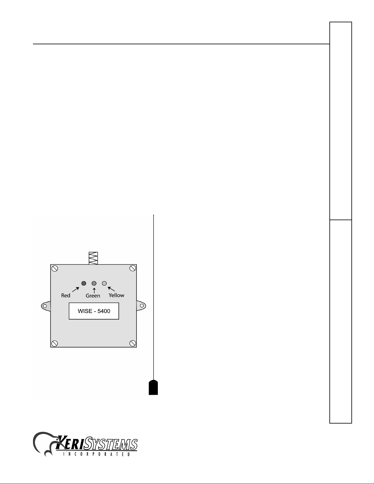
The RPB-200 RF Receiver
The RPB-200 can be used with the PXL-250W or the PXL-100 with an OB-7. It provides a range of up to 50 feet when
used in conjunction with a standard hard wire antenna and either mini or standard transmitter cards. There are no
switches or jumpers to set; simply install the enclosure, make the wiring connections, and the unit is ready for use.
NOTE: This document provides the instructions for connecting the RPB-200 to the PXL-250W Tiger Controller or the
PXL-100 Smart Controller. Please refer to the installation instructions provided by the RPB-200's manufacturer for
instructions on enclosure mounting and for providing power to the RPB-200.
1.0 Dimensions
1.1 Enclosure
• 5.00 inches High x 5.00 inches Wide x 2.00 inches Deep
• 12.7 cm High x 12.7 cm Wide x 5.1 cm Deep
1.2 Antenna
• 11 inches High
•28 cm High
Quick Start Guide
Figure 1: RPB–200 RF Receiver
RPB–200
1530 Old Oakland Road, Suite 100 01825-200 Rev. B
San Jose, CA 95112 USA
(800) 260-5265 (408) 451-2520 FAX (408) 441-0309
Web: http://www.kerisys.com E-mail: sales@kerisys.com Page 1 of 8
Page 2
RPB–200: RF Receiver
2.0 Connections
The connection between the PXL controller and the RPB-200 is made through a 7 conductor, shielded, stranded, AWG
24 wire cable (such as Belden 9537 or a larger gauge).
Before running a cable to the RPB-200 you must drill a 1/4 inch diameter hole in the case of the RPB-200 to
accommodate the cable. After the cable has been connected to the RPB-200, the cable/hole can be sealed with a
silicone/RTV type sealer.
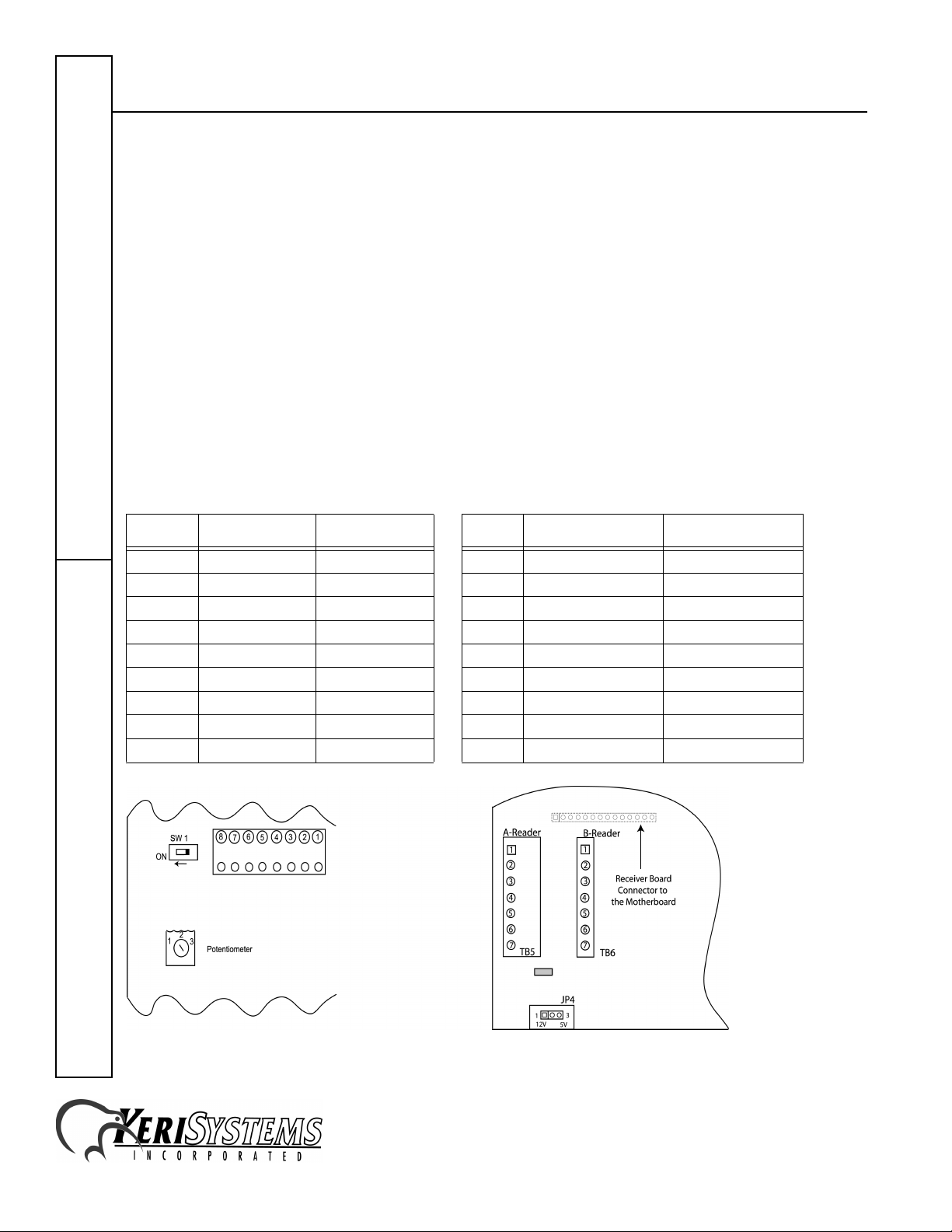
2.1 Connecting to the RPB-200
The cable connects to the terminal strip on the RF receiver board, pins 1 through 8 (excluding pins 3 and 6). The cable
shield is not connected at the RPB-200.
2.2 Connecting to the PXL-250W
For an "A" reader connection, the cable connects to TB5 pins 1 through 7 (excluding pin 2). For a "B" reader
connection, the cable connects to TB6 pins 1 through 7 (excluding pin 2).
RPB–200 Cable Connections Connecting to the PXL–250W at TB5/TB6
Quick Start Guide
Pin # Function Wire Color Pin # Function Wire Color
1 Ground Black 4 Ground Black
–– –
2Power Red
3 no connection –
4 Red LED Brown
5 Green LED Orange
6 Yellow LED –
7 Data 1 White
8 Data 0 Green
RPB–200
4 Shield Silver
3 12V Power Red
2not used –
6 Red LED Brown
5 Green LED Orange
–– –
7 Data 1 White
1 Data 0 Green
Figure 2: RPB–200 Connections Figure 3: PXL–250W Connections
1530 Old Oakland Road, Suite 100 01825-200 Rev. B
San Jose, CA 95112 USA
(800) 260-5265 (408) 451-2520 FAX (408) 441-0309
Web: http://www.kerisys.com E-mail: sales@kerisys.com Page 2 of 8
Page 3
RPB–200: RF Receiver
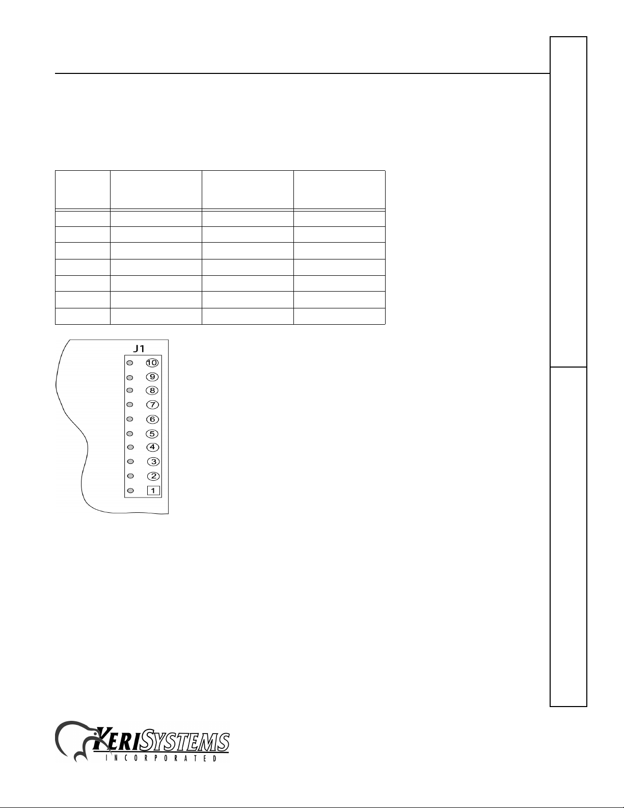
2.3 Connecting to the Design 5 PXL-100
For the RPB-200 to work with a PXL-100, the PXL-100 must have an OB-7 Wiegand Interface option board installed.
The cable connects to J1 on the OB-7, pins 1 and 2; and J2 on the OB-7, pins 1, 2, 5, and 6.
2.3.1 Connecting to the PXL–100 @ OB–7, J1
Quick Start Guide
Pin #
1 0V Ground Black
10V Shield Silver
212V 12V PowerRed
3–––
4–––
5–––
6–––
OB–7 PCB
Marking
Function Wire Color
RPB–200
Figure 4: PXL–100/J1 Connections on the OB–7
1530 Old Oakland Road, Suite 100 01825-200 Rev. B
San Jose, CA 95112 USA
(800) 260-5265 (408) 451-2520 FAX (408) 441-0309
Web: http://www.kerisys.com E-mail: sales@kerisys.com Page 3 of 8
Page 4

RPB–200: RF Receiver
2.3.2 Connecting to the PXL–100 @ OB–7, J2
Pin #
1 LED Red LED Brown
2BEEPER not used –
3–––
4–––
4–––
5 M IP B Data 1 White
6 M IP A Data 0 Green
OB–7 PCB
Marking
Function Wire Color
Quick Start Guide
Figure 5: PXL–100/OB–7 Connections
NOTE: Please contact customer support at Keri Systems for information regarding connecting an RPB-200 to a Design
4 PXL-100. A Design 4 PXL-100 can be identified by the location of its power connection made at the middle of the left
edge of the printed circuit board.
RPB–200
1530 Old Oakland Road, Suite 100 01825-200 Rev. B
San Jose, CA 95112 USA
(800) 260-5265 (408) 451-2520 FAX (408) 441-0309
Web: http://www.kerisys.com E-mail: sales@kerisys.com Page 4 of 8
Page 5

RPB–200: RF Receiver
3.0 Testing and Changing Receiver Range
3.1 Testing Receiver Range
You may want to test the receiver range.
1. Switch SW1 on the RPB–200 to the “ON” position (see Figure 2 on page 2).
2. Activate a transmitter card within range of the receiver.
3. If the receiver is functioning properly and the transmitter card has been activated within range, the yellow LED on
the receiver will flash once.
4. Repeat the process moving away from the receiver. When the yellow LED does not flash, you have moved outside
of the receiver’s range.
3.2 Changing Receiver Range
If the receiver range is set at a distance either too near or too far, you my change the distance.
1. To increase the receiver range distance, turn the potentiometer clockwise (see Figure 2 on page 2).
2. To decrease the receiver range distance, turn the potentiometer counter-clockwise (see Figure 2 on page 2).
3. Repeat steps 1–3 in Testing Receiver Range, until you have found the range that will work best for you.
NOTE: When you have the receiver range set at the distance you want, be sure to switch SW1 back to the OFF position.
Quick Start Guide
4.0 Installation Verification
If desired, following installation, receiver operation can be verified within the Doors program. Perform the following
steps to verify receiver operation.
1. Enter the Doors program.
2. Click on the Operate ⇒ Start Monitor pull-down menu option.
3. Click on the Monitor button.
4. Click on the View Window 1 button (its default definition is to show all events that occur).
5. Activate a transmitter card within the range of the receiver.
6. An "Unknown Key" message will appear in the monitor view window, verifying the key was read and its data was
transferred to the controller.
RPB–200
1530 Old Oakland Road, Suite 100 01825-200 Rev. B
San Jose, CA 95112 USA
(800) 260-5265 (408) 451-2520 FAX (408) 441-0309
Web: http://www.kerisys.com E-mail: sales@kerisys.com Page 5 of 8
Page 6

RPB–200: RF Receiver
5.0 Enrollment Procedure
Once installation is verified and the receiver range has been set, you may begin enrolling transmitter cards. Enrolling
transmitter cards is accomplished the same as enrolling cards (see Setup Cards
01821-002.
• When presenting to the reader for card enrollment, the receiver is used as the main reader. To present the
transmitter card for enrolling, activate the transmitter card within range of the receiver.
• The card number, to be used for block enrolling, may be found on the label of the transmitter card. An example of
where the information may be located on the transmitter card is shown in Figure 6.
in the
Doors32
Users Guide – P/N
Quick Start Guide
Figure 6: Transmitter Card Number
RPB–200
1530 Old Oakland Road, Suite 100 01825-200 Rev. B
San Jose, CA 95112 USA
(800) 260-5265 (408) 451-2520 FAX (408) 441-0309
Web: http://www.kerisys.com E-mail: sales@kerisys.com Page 6 of 8
Page 7

RPB–200: RF Receiver
6.0 Troubleshooting the Receiver Installation
Problem Probable Cause Corrective Action
Quick Start Guide
The controller does not
recognize the RPB-200.
The RPB-200 is
recognizing the
transmitter card, but not
showing up on the
software.
The RPB–200 has a
short receive range.
1. One or more of the receiver’s
wiring connections are incorrect.
2. Insufficient power is being
provided to the RPB–200.
3. The battery in the transmitter
card is weak or dead.
4. PXL–100 ONLY – JP9 on the
OB–7 is installed.
1. Data 0 and Data 1 are reversed. • Switch Data 0 and Data 1 positions.
1. The RPB–200 range adjustment
potentiometer should be
increased.
2. The antenna is shielded by
metal.
3. The battery in the transmitter
card is weak or dead.
• Power down the controller and the receiver
and verify the wiring
• connections are correct per the instructions
provided in the Connections section on
page 2.
• Verify the power supply voltage and wiring
for the RPB–200 is correct (refer to the
RPB manual provided with the RPB unit).
• Verify battery strength or replace the
battery.
• Refer to the OB–7 Quick Start Guide and
verify there is not a jumper across JP9.
• Refer to the Receiver Installation sheet
provided by the Receiver’s manufacturer
for range adjustment instructions.
• Relocate the enclosure or the antenna away
from metal surfaces.
• Verify battery strength or replace the
battery.
RPB–200
1530 Old Oakland Road, Suite 100 01825-200 Rev. B
San Jose, CA 95112 USA
(800) 260-5265 (408) 451-2520 FAX (408) 441-0309
Web: http://www.kerisys.com E-mail: sales@kerisys.com Page 7 of 8
Page 8

RPB–200: RF Receiver
Quick Start Guide
RPB–200
This page is intentionally left blank.
1530 Old Oakland Road, Suite 100 01825-200 Rev. B
San Jose, CA 95112 USA
(800) 260-5265 (408) 451-2520 FAX (408) 441-0309
Web: http://www.kerisys.com E-mail: sales@kerisys.com Page 8 of 8
 Loading...