

Page 1

PXL-380 Access Controller
TB6
RS-485
Network
12 VDC
Power
Lock
Relay
Inputs
ADDRESS
POWER
NOISE
TP3
S1
LED 8
COMM
LED 9
TB1
GND
TP2
Reader Signal Strength
Test Points
TxRx -
TxRx +
Shield
+12 VDC
Negative
Earth Ground
Lock - NO
Lock - Common
Lock - NC
Door Switch - NC
Ground
RTE - NO
- not available Ground
Global Unlock - NO
Auxiliary RTE "A" - NO
Lithium
Battery
A-Reader B-Reader
JP10
Satellite Board Connectors
FUSE
TB5
1
2
3
4
5
6
7
7
1
2
3
4
5
6
TB3
1
2
3
4
TB2
1
3
2
1
2
3
Comm Board / LAN
Connectors
LED 1
485
JP9
LED12LED11
LED6
EPROM
LOCK
LINE1 LINE2
A & B Reader Wiring
(See Figure 2)
TB4
1
2
3
4
5
6
PIC - MIOP
Lock
Relay
- not available -
Seating Area for
Comm Board or LAN Unit
01239-004 Rev. C
JP11
Short Pins for
Master Controller
Wiegand-ONLY Components
Installation Guide
The PXL-380 is a 1-door, 2-reader door controller that can manage access and egress at a single door, or access for two
doors using Keri’s Proximity Readers and an SB-23 Satellite Board. There are both Keri Proximity and Wiegand versions
of this controller. This document contains basic information for the installation of the PXL-380 Access Controller.
1.0 PXL-380 Access Controller
Page 1 of 7 P/N: 01239-002 Rev. D
Page 2
PXL-380 Access Controller
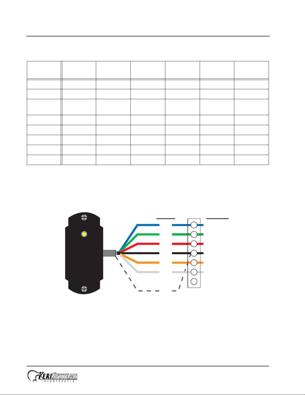
2
3
5
6
7
Blue
Green
Red
Black
Brown
White
Silver
Wiring applies to both TB-5 / A-Reader and TB-6 / B-Reader.
- not used -
Antenna
Beeper
Power
Ground
Green LED
Red LED
Cable Shield
- not used -
Wire Color Function
1
4
TB-5/6
Installation Guide
Table 1: Cable Matrix
Conductors Shield
Twisted
Pair
Stranded AWG
Max
Length
485 Network 2 Y Y Y 24 4,000 ft
Power 2 N N Y 18 200 ft
Earth
Ground
1 N N N 18 as short
as possible
Output 2 N Y Y 20 100 ft
Input 2 N N Y 22 100 ft
Serial Comm 3YNY2450 ft
Modem 5YNY2450 ft
Readers 6 Y Y Y 24 500 ft
2.0 Reader Connections
2.1 Keri MS Reader
Page 2 of 7 P/N: 01239-002 Rev. D
Page 3

PXL-380 Access Controller
2
3
5
6
7
Wiring applies to both TB-5 / A-Reader and TB-6 / B-Reader.
Refer to the Wiegand Reader’s documentation for wire colors.
Data0
Beeper
Power
Ground
Green LED
Red LED
Cable Shield
Data1
Function
1
4
TB-5/6
123456
USB Mini-B
Connection
JP1 JP2
JP1 and JP2 on upper pins
for direct-connect serial and
modem communication.
JP1 JP2
JP1 and JP2 on lower pins
for USB to serial communication.
JP1 JP2
D5/D6 - Comm Activity LEDs
USB to Serial
D3/D4 - Comm Activity LEDs
RS-232/Modem
DB-9M
(back side of connector)
Direct-to-PC Connection Modem Connection
DB-9F
(back side of connector)
12345
7
123456
23 51
123456
Installation Guide
2.2 Wiegand Reader
3.0 Comm Board
The Comm Board provides the external link from master controller to host PC. Comm Boards are only needed for the
master controller for each site. The Comm Board provides communication via either RS-232 serial/direct-connect,
modem, or USB. For Ethernet/LAN communications a LAN-520 is still required (replacing the Comm Board). The
Comm Board is not provided with the controller, but must be ordered separately.
Page 3 of 7 P/N: 01239-002 Rev. D
Page 4

PXL-380 Access Controller
Installation Guide
3.1 USB Communication
The Comm Board is capable of USB serial communication with the host PC using a Mini-B cable. The maximum cable
length from PC to controller is 16 feet (5 meters). Perform the following to set the Comm Board for USB communication:
NOTE: Windows XP operating system screen examples are shown.
1. On the Comm Board, set JP1 and JP2 per the above draw ing.
2. Plug the Comm Board onto the controller.
3. Plug the USB cable into the Comm Board.
4. Power up the controller.
5. Plug the USB cable into a port on the PC.
6. Install the USB driver if necessary. This driver will install automatically if there is a connection to the Internet, and is
also included on the software DVD (Drivers\FTDI Driver folder).
7. Open the Device Manager window:
- Start > Run > devmgmt.msc
8. View the list of available COM ports.
Page 4 of 7 P/N: 01239-002 Rev. D
Page 5

PXL-380 Access Controller
Installation Guide
9. Disconnect the USB cable and note the COM port that disappears. This is the COM port assigned to the Com m
Board.
10. Reconnect the USB cable and verify the COM port reappears with the same port assignment.
11. Note this COM port number assigned to the Comm Board for assignment in Doors.NET.
4.0 Resetting the Controller's RAM
If you're turning system power on for the first time or have just changed the EPROM/PIC, the PXL-380 controller's RAM
must be reset before performing any other action. This clears any spurious information that may be in the RAM in
preparation for entering your access control information. Before applying power, insert a jumper across pins 1 and 2 of
JP10 on the controller. Hold the S1 Options Button down and turn the controller's power on. The beeper for the reader
attached to the controller will beep as power comes on followed by a beep-beep indicating the controller's firmware has
reset the controller's RAM. Release S1. Turn system power off and remove the jumper on JP10. When the controller is
powered up it is now ready to receive information from Doors.NET.
NOTE: Resetting the system RAM completely erases all information within the PXL-380 controller. Therefore, once a
reset has been performed on the controller all the access control information will need to be sent again from the software.
5.0 Controller Addressing
To view the controller's address, click S1. The controller's address will appear on the address display for 2 to 3 seconds.
5.1 The Master Controller
Every site must have one Master Controller, through which communication to the host PC is made and to which all slave
controllers are connected. The Master Controller must be set as address 1 and it must have the Master Controller jumper
JP 11 ON (refer to the drawing on page 1). All slave controllers must not have a jumper on JP11 and can have addresses
between 2 and 128. A Comm Board is required for the Master Controller to communicate with the host PC. The Comm
Board is not provided with PXL controllers, but must be ordered separately. Refer back to Section 3.0 for information on
the Comm Board.
Page 5 of 7 P/N: 01239-002 Rev. D
Page 6

PXL-380 Access Controller
NO - Relay
Common - Lock / Alarm - Relay
NC - Relay
–
+
Power
Supply
Fail-Secure
Electric Lock Device
or
Alarm
–
+
–
+
Power
Supply
Fail-Safe
Electric Lock
Device
–
+
Terminal Block
Terminal Block
NO - Relay
Common - Lock / Alarm - Relay
NC - Relay
1
2
3
1
2
3
Installation Guide
5.2 Setting the Controller's Address
To set the desired operating address for the controller, verify the jumper to JP10 is NOT installed. Hold the S1 Options
Button down and turn the controller's power on. The beeper for the reader attached to the controller will beep as power
comes on. Release S1. The address display LEDs then become active and the controller's address can be set. The address
range is from 1 to 128 (the Master Controller must be set to address 1).
Quickly double clicking S1 toggles between increasing and decreasing the controller address. The top LED character will
display either a “+” or a “-” to show which direction is active. A single click of S1 changes the controller address by 1. If
you're at address 128, a +1 click will roll the address over to 1; conversely, if you're at address 1 a -1 click will roll the
address over to 128. Holding S1 down rapidly scrolls through the addresses.
After the new address has been set, you must wait approximately 30 seconds after releasing the S1 button. There is a timer
in the controller's firmware that assumes that after 30 seconds of inactivity (no address click s), the entered address is the
desired address for that controller. When the 30-second timer expires, there will be a beep-beep-beep from the reader
indicating the controller has recognized and accepted the new address and the address LEDs will turn off. To ensure the
address change will be recognized by Doors.NET, power down the controller. Then, after verifying th e JP10 jum per is
NOT installed, apply power to the controller. The controller is now ready to be used under the new address.
NOTE: When a controller’s address is changed, its RAM is automatically reset, clearing all configuration information
that may have been downloaded to the controller. A Total Update must be performed from Doors.NET.
6.0 Transient Protection
A transorb is provided with the controller ship kit. It is used to protect the controller from voltage spikes induced on the
relay wiring by absorbing the excess voltage and slowly releasing it back into the circuit. Keri strongly recommends
wiring in the transorb provided with the controller ship kit. Refer to the Transorb Wiring Diagram below.
6.1 Isolation Relays
For locking devices that may induce heavy voltage spikes – Mag Locks and devices with heavy-duty solenoids such as
turnstiles, vehicle gates, and overhead doors – Keri recommends using an isolation relay. Keri has an Isolation Relay Kit
(p/n IRP-1). Please refer to the IRP-1 Isolation Relay Installation Guide (p/n 01833-001) for detailed information.
Page 6 of 7 P/N: 01239-002 Rev. D
Page 7

PXL-380 Access Controller
Installation Guide
7.0 Contact Keri Systems
Keri USA Keri UK, Ireland, Europe
2305 Bering Drive
San Jose, CA 95131
T elephone: (800) 260-5265
(408) 435-8400
Fax: (408) 577-1792 Fax:+ 44 (0) 1763 274 106
Web: www.kerisys.com Web:www.kerisystems.co.uk
E-mail: sales@kerisys.com
techsupport@kerisys.com
end of document
Park Farm Industrial Estate
Telephone: + 44 (0) 1763 273 243
E-mail:sales@kerisystems.co.uk
tech-support@kerisystems.co.uk
Unit 17
Ermine Street
Buntingford
Herts SG9 9AZ UK
Page 7 of 7 P/N: 01239-002 Rev. D
 Loading...