

Page 1
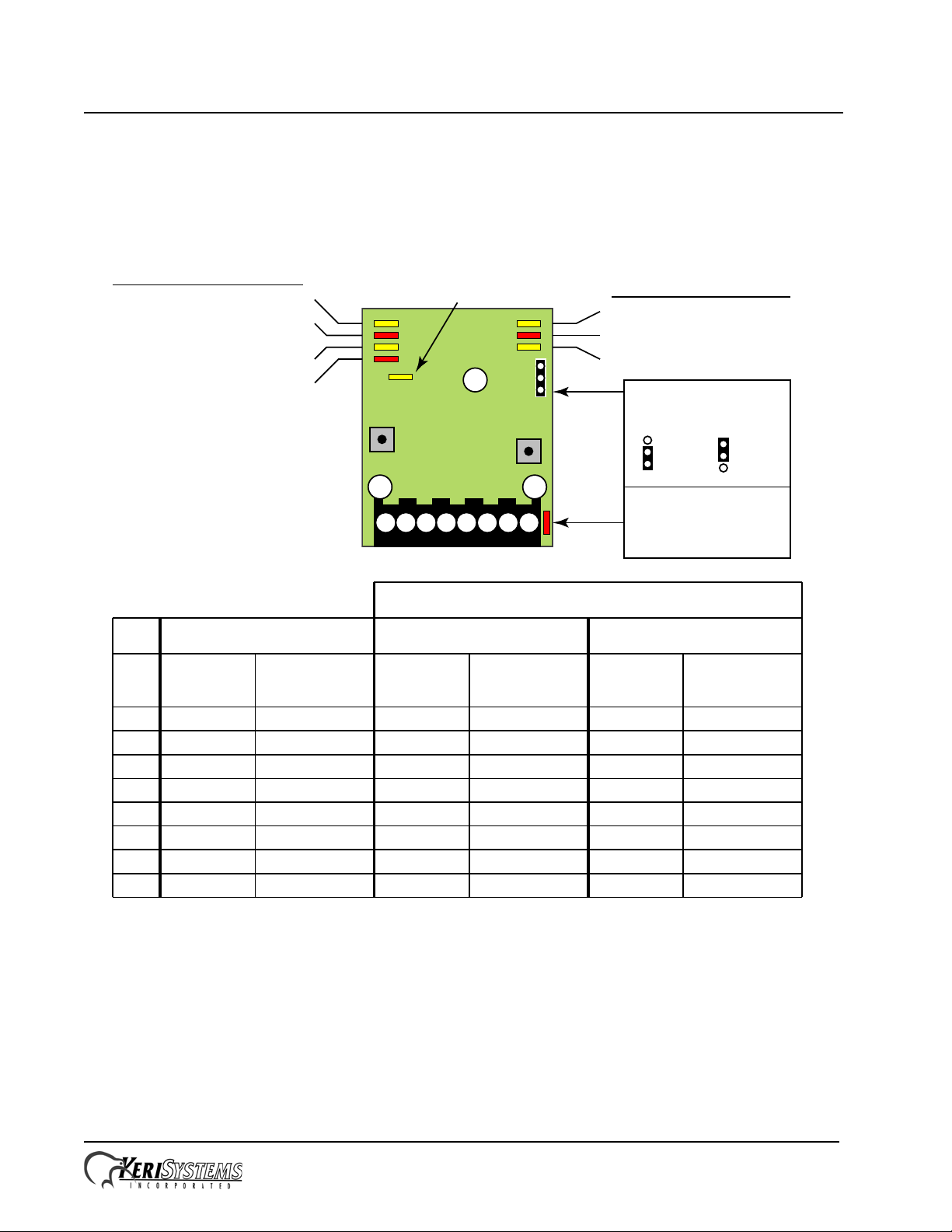
NXT Reader Interface Module
P/N: 02501-002 Rev. J
D10 - 12VDC
Reader Power
Selected
SW2
SW1
J2
1 2
3
4
5 6 7 8
NXT-RM Installation Drawing
Reader LED Configuration
Step
Switch
Select
Switch
12VDC
5VDC
J2 Jumper Settings
for Reader Power
Keri MS Reader - D4
Wiegand Reader - D5
NXT-6RK Keypad Reader - D6
Wiegand Combo Reader - D7
Reader Type
D1 - Single-line, three-color LED
D2 - Dual-line LED - Keri default
D3 - Single-line, two-color LED
RS-485 Comm - D8
1
2
3
4
5
6
7
8
Antenna
Beeper
Red LED
Green LED
+ 12 VDC
Ground
n/a
n/a
Blue
Green
White
Brown
Red
Black & Shield
n/a
n/a
n/a
Beeper
LED
n/a
+ 12 VDC
Ground
Data0
Data1
n/a
Blue
Brown
n/a
Red
Black & Shield
Green
White
n/a
Beeper
Red LED
Green LED
+ 12 VDC
Ground
Data0
Data1
n/a
Blue
Brown
Orange
Red
Black & Shield
Green
White
Single-Line LED Dual-Line LEDKeri MS Reader
Wiegand Reader
Connection Wire Color
* Farpointe
Wire Color
* Farpointe
Wire Color
ConnectionConnectionPin #
* For other Wiegand reader types, please refer to the reader manufacturer’s color code.
Installation Guide
1.0 Wiring and Layout Diagrams
1.1 Reader Interface Module (RIM)
NOTE: This equipment has been tested and found to comply with the limits for a Class A digital device, pursuant to Part
15 of the FCC Rules. These limits are designed to provide reasonable protection against harmful interference when the
equipment is operated in a commercial environment. This equipment generates, uses, and can radiate radio frequency
energy and, if not installed and used in accordance with the instruction manual, may cause harmful interference to radio
communications. Operation of this equipment in a residential area is likely to cause harmful interference in which case
the user will be required to correct the interference at his own expense.
Page 1 of 5 P/N: 02501-001 Rev. L
Page 2
NXT Reader Interface Module
Installation Guide
2.0 Specifications
2.1 Size
• When mounted on the NXT Controller
- 6.50 inches high by 5.50 inches wide by 2.50 inches deep, not including wiring connectors
- 16.51 cm by 13.97 cm by 6.35 cm
2.2 Power/Current Requirements
• 10 to 14 VDC @ 100 mA (maximum current draw at 12 VDC)
2.3 Operating Conditions
• 32°F to 150°F (0°C to 60°C) – 0% to 90% Relative Humidity, non-condensing
2.4 Cable Requirements
The total RIM to reader cable length must be less than 500 feet.
NOTE: On long cable runs, cable resistance causes a drop in voltage at the end of the cable run.
Ensure the appropriate power and current for your device is available at the device at the end of the
cable run.
Table 1: Cable Requirements
Connection
RIM to Keri-MS or
Wiegand Single-line
LED Reader
RIM to NXT-6RK
or Wiegand Dual-
line LED Reader
a. Heavier gauges than those listed are always acceptable.
Total Run
Length
500 feet 6 Y Y N 22 9536
500 feet 7 Y Y N 22 9537
# of
Conductors
Shielded Stranded
Twisted
Pair
AWG
a
Equivalent
Belden
3.0 RIM Configuration
The RIM allows either Keri MS or Wiegand readers/credentials to be recognized and read by NXT
controllers. The default RIM configuration is for an MS-Series Reader using two line LED control
(multi-color). Perform the following steps to configure the RIM for your application. Refer to the
Drawing on page 1 for switch and LED locations, and the Table on page 3 for switch and LED
definitions.
Page 2 of 5 P/N: 02501-001 Rev. L
Page 3

NXT Reader Interface Module
Installation Guide
3.1 Enter Programming Mode
1. Hold down both SW1 and SW2 for about two seconds.
2. All seven LEDs on the RIM will flash three times.
3. Release both SW1 and SW2, and the unit is now in configuration mode.
4. Once in configuration mode, SW1 steps between options - SW2 selects the currently displayed
option.
3.2 Select Your Reader Type
The Keri MS (D4), Wiegand (D5), Keri Keypad (D6), and Wiegand Keypad/Reader Combo (D7)
types are currently supported.
1. Press SW1 to step through the supported reader types. Each press of SW1 will step to the next
reader type.
2. When the desired reader type LED is illuminated, press SW2. The reader type is now set.
3. If you have selected Wiegand (D5), Keri Keypad (D6), or Wiegand Combo (D7) reader mode, the
unit is now ready to configure the RIM’s LED line control mode. Skip to section 3.3 for
configuration instructions.
4. If you have selected Keri MS (D4) reader mode, press SW2 twice. The RIM is now configured
and the unit reboots to accept the new parameters. All seven LEDs will flash three times as the
unit reboots with the new configuration parameters. When the LEDs stop flashing, the unit is
operational.
NOTE: Do not remove power from the RIM during the reboot process. Loss of power during
rebooting will invalidate any configuration changes you have made.
3.3 Select Your Wiegand Reader LED Line Configuration
Dual-line control is the default RIM setting for LED line configuration. This is the desired setting for
the Keri Keypad reader . Perform the following steps to switch between single-line and dual-line LED
control.
1. Press SW1 to step through the supported LED line configuration types. Each press of SW1 will
step to the next LED line type.
2. When the desired LED line control mode LED is illuminated, press SW2. The LED line control
mode is now set.
3. Press SW2 twice and the RIM is now configured and the unit reboots to accept the new
parameters.
4. The RIM’s LEDs will be off for about 10 seconds as the unit resets itself. All seven LEDs will
flash as the unit is rebooting with the new configuration parameters. When the LEDs stop
flashing, the unit is operational.
NOTE: Do not remove power from the RIM during the reboot process. Loss of power during
rebooting will invalidate any configuration changes you have made.
Page 3 of 5 P/N: 02501-001 Rev. L
Page 4

NXT Reader Interface Module
Installation Guide
3.4 Verifying RIM Configuration
The corresponding reader type and line control mode LEDs are illuminated during operation. Refer to
the Drawing on page 1 for switch and LED locations, and the Table on page 2 for switch and LED
definitions to confirm your configuration settings.
Table 2: Reader Interface Module LED Guide
LED Reader Type
D4 Keri MS Series
Keri factory default setting
D5 Wiegand
D6 Keri NXT-6RK Keypad
D7 Wiegand Reader/Keypad Combo
LED Control
D1 single wire LED control – red, green, amber, off
D2 two wire LED control – red, green, amber, off
Keri factory default setting
a
D3
standard setting for Wiegand Readers using a single wire to drive the
D8 RS-485 Bus
D10 lit when set for 12 VDC reader power
a. Table is valid for RIM Firmware v03.01.06 and later. Please upgrade your firmware as necessary.
single wire LED control – red, green, off
LED (no amber)
Communication Active
J2 Reader Power Setting
Page 4 of 5 P/N: 02501-001 Rev. L
Page 5

NXT Reader Interface Module
Installation Guide
4.0 Contact Keri Systems
Keri USA Keri UK, Ireland, Europe
2305 Bering Drive
San Jose, CA 95131
Telephone: (800) 260-5265
(408) 435-8400
Fax: (408) 577-1792 Fax:+ 44 (0) 1763 274 106
Web: www.kerisys.com Web:www.kerisystems.co.uk
E-mail: sales@kerisys.com
techsupport@kerisys.com
end of document
Park Farm Industrial Estate
Telephone: +44 (0) 1763 273 243
E-mail:sales@kerisystems.co.uk
tech-support@kerisystems.co.uk
Unit 17
Ermine Street
Buntingford
Herts SG9 9AZ UK
Page 5 of 5 P/N: 02501-001 Rev. L
 Loading...