

Page 1
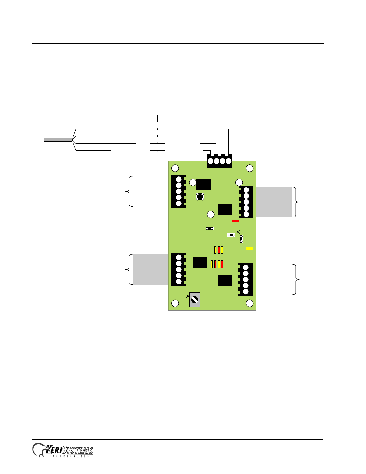
NXT 4x4
TB24
TB25
TB22
TB23
TB21
J23
Relay
Relay
Relay
Relay
IO Minus (White)
Power (Red)
Ground (Black)
4
321
Ground
Input
NC - Relay
Common - Relay
NO - Relay
NO - Relay
Common - Relay
NC - Relay
Input
Ground
Port 3
Port 4
Port 1
P/N: 01998-002 - Rev. E
1
2
3
4
5
5
4
3
2
1
1
2
3
4
5
5
4
3
2
1
J1
IO Plus (Green)
NO - Relay
Common - Relay
NC - Relay
Input
Ground
Port 2
Ground
Input
NC - Relay
Common - Relay
NO - Relay
JP1
J2
RS-485
J24
PCB Earth Ground Lug
cde
a
fghi
b
NXT-4x4
Installation Drawing
Tamper Switch Input
Shielded 4-Conductor CablingShielded CAT-5 Cabling
Blue with Stripe
Brown/Green/Orange w/o Stripe
Brown/Green/Orange with Stripe
Blue
total
cable length
500 feet max
(150 m)
Installation Guide
Section 1 – Wiring and Layout Diagrams
Section 2 – Specifications and Cable Requirements
Section 3 – Keri Contact Information
1.0 Wiring and Layout Diagrams
1.1 NXT-4x4 I/O Module
See Table 1 on page 2 for LED definitions.
NOTE: This equipment has been tested and found to comply with the limits for a Class A digital device, pursuant to Part 15 of the FCC Rules. These
limits are designed to provide reasonable protection against harmful interference when the equipment is operated in a commercial environment. This
equipment generates, uses, and can radiate radio frequency energy and, if not installed and used in accordance with the instruction manual, may cause
harmful interference to radio communications. Operation of this equipment in a residential area is likely to cause harmful interference in which case the
user will be required to correct the interference at his own expense.
Page 1 of 4 P/N: 01998-001 Rev. G
Page 2
NXT 4x4
Installation Guide
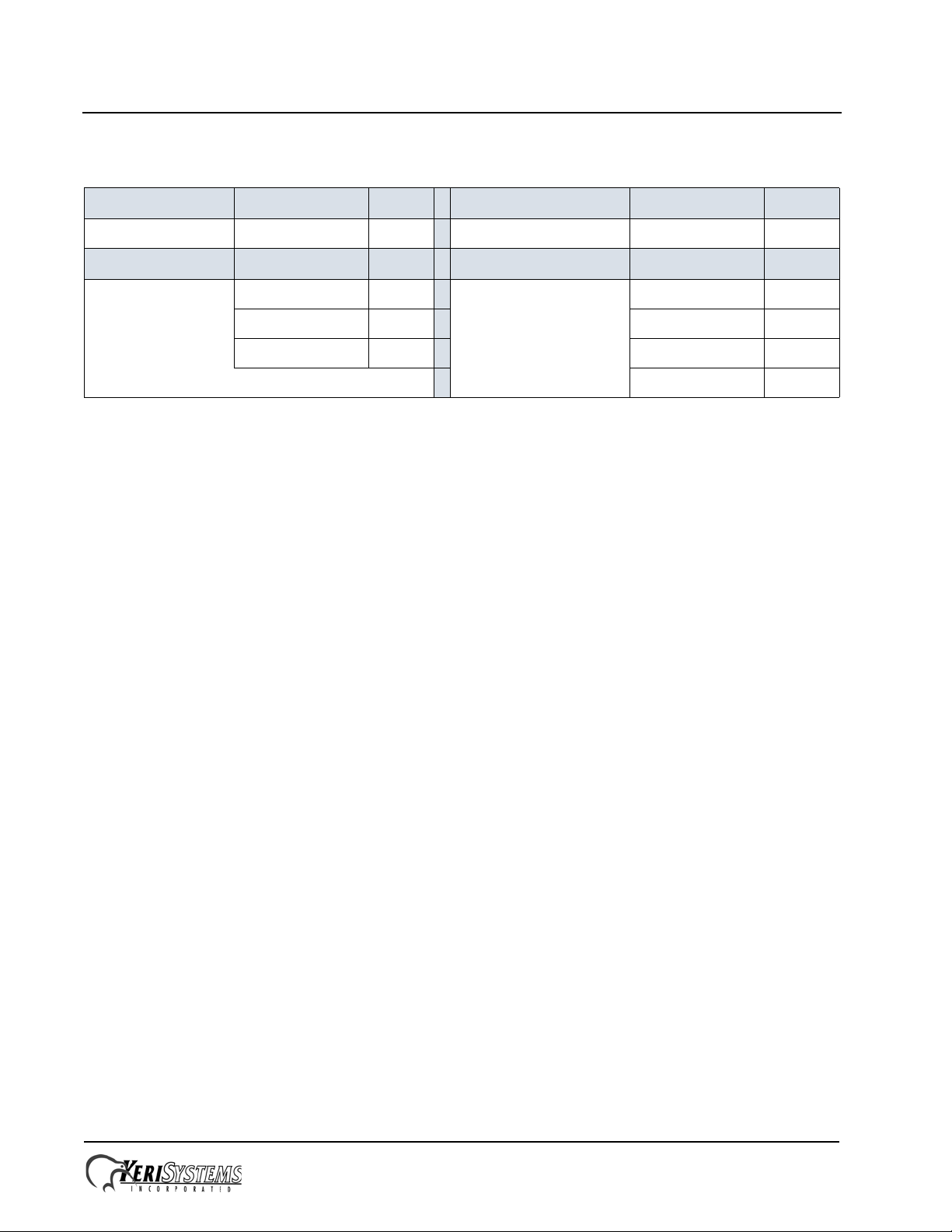
Table 1: 4x4 LEDs
Power Purpose LED Future Application Purpose LED
indicator a undefined b
Utility Purpose LED Relay State Purpose LED
RS-485 Tx c Bus 1 f
User 1 d
User 2 e
Bus 2 g
Bus 3 h
Bus 4 i
2.0 Specifications
2.1 NXT-4x4 Dimensions
• 4x4 PCB
- 5.25 inches tall by 3.10 inches wide by 1.00 inches deep, not including wiring connectors
- 13.33 cm by 7.87 cm by 2.54 cm
• 4x4 Enclosure
- 8.00 inches tall by 7.00 inches wide by 2.75 inches deep
- 20.32 cm by 17.78 cm by 6.98 cm
2.2 Power Requirements
• 10 to 14 VDC @ 0.5 A (maximum current draw for a fully loaded NXT-4x4)
2.3 Current Requirements at 12 VDC
• 250 mA max for each NXT-4x4
NOTE: If you are driving an electronic locking device (magnetic lock, door strike, etc.) using the same power supply as
the 4x4, ensure the power supply provides enough current to drive every device connected, including an adequate safety
margin.
2.4 Relay Contact Rating
• 1 A @ 24 VDC
2.5 Operating Conditions
• 32°F to 150°F (0°C to 60°C) – 0% to 90% Relative Humidity, non-condensing
2.6 Cable Options
RS-485 bus runs can daisy-chain together an NXT-4x4 and NXT-Reader on one line. The total cable run distance should
be less than 500 feet from the NXT controller for runs with 4x4s and less than 1,000 feet for Reader-only runs.
NOTE: Cable resistance causes a dr op in voltage at the end of long cable runs. Ensure the appropriate power and current
for your device is available at the device at the end of the cable run. Heavier gauge cable reduces this affect.
NOTE: Keri does not recommend hot-plugging a Reader, RIM, or 4x4 into an NXT controller.
Remove power from the controller prior to connecting these devices.
Page 2 of 4 P/N: 01998-001 Rev. G
Page 3
NXT 4x4
Installation Guide
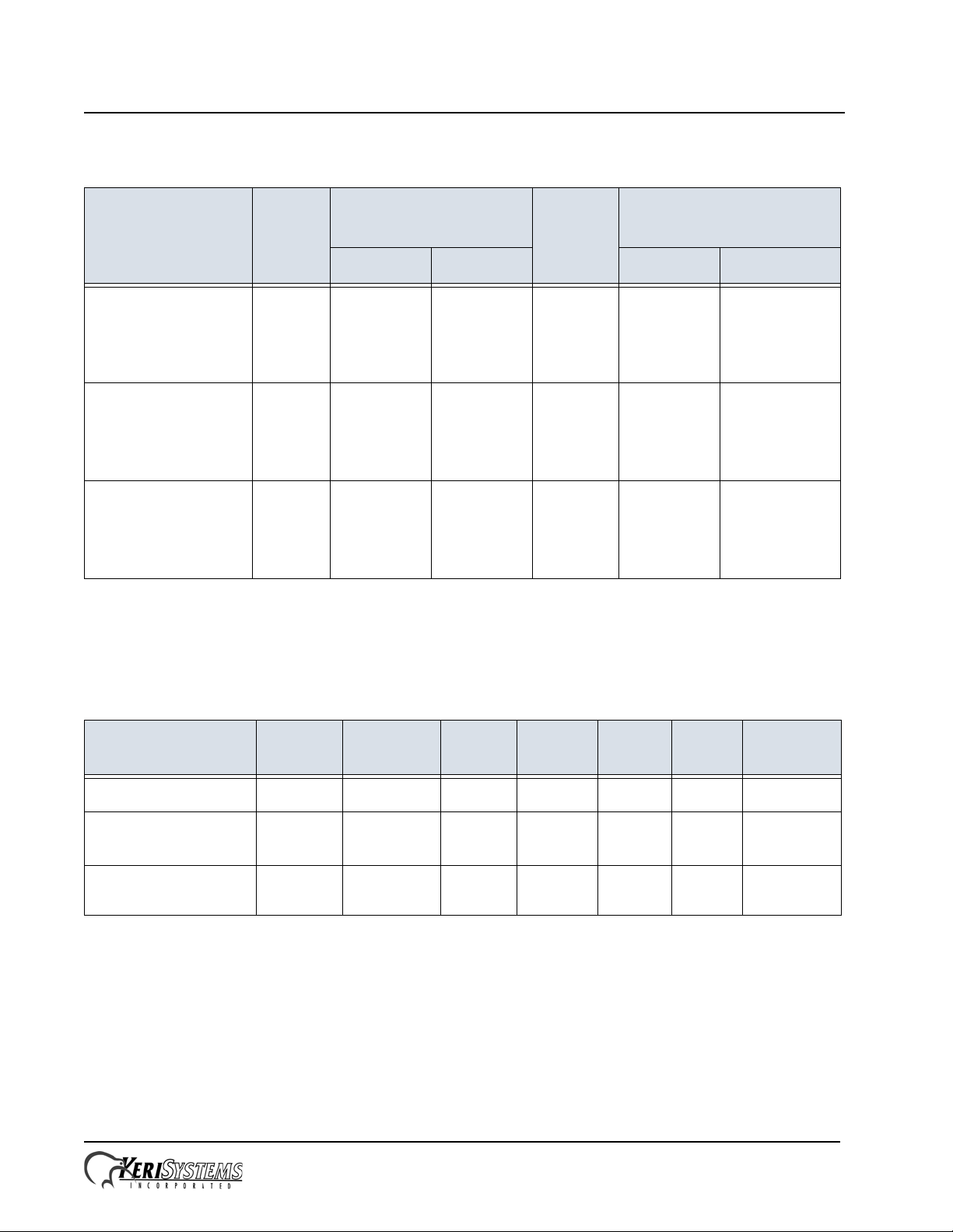
Table 2: Reader and 4x4 Cable Options
Total
Connection Type
Run
Length
RS-485 bus
from NXT-2D/-4D
to NXT-4x4 only
RS-485 bus
from NXT-2D/-4D
to NXT-4x4
and NXT Readers
RS-485 bus
from NXT-2D/-4D
to NXT Readers only
a. Keri recommends this cable type for best system performance.
b. Keri’s preferred low-cost option. Keri has no suggested vendor for this type of cable.
c. Use care when routing this type of cable as it can make the system more susceptible to EMI.
up to
500 feet
up to
500 feet
up to
1,000 feet
Shielded, Stranded,
2 Twisted-Pa ir
a
CAT-5
b
AWG Suggest AWG Suggest
18 - Data plus
4x4 Power
22 - Data only
18 - Data plus
4x4 Power
22 - Data only
22 for Data Belden
Belden
8723
Belden
8723
8723
unshielded 18 - Data plus
shielded 18 - Data plus
shielded 22 for Data Windy City:
Shielded, Stranded,
4-Conductor
4x4 Power
22 - Data only
4x4 Power
22 - Data only
c
Windy City:
414302-S
West Penn: 244
Tappan:
1880AB4M-CM
Windy City:
414302-S
West Penn: 244
Tappan:
1880AB4M-CM
416303-S
West Penn: 241
Tappan:
2280AB4M-CM
Table 3: Controller Power, Inputs, and Outputs Cable Requirements
Connection
controller power
Total Run
250 feet
earth ground shortest
inputs and outputs
c
Length
a
b
path
500 feet 2 N Y n/a 22 no specific
# of
Conductors
Shielded Stranded
Twisted
Pair
AWG
2 N Y Y 18 8461
1 N N n/a 18 no specific
Belden
Equivalent
requirement
requirement
a. To meet CE and C-tick regulat ions, the length of the controller power line can be no longer than 3 Meters
(9.85 feet).
b. Use the shortest possible path from earth ground point to PCB. Connect the earth ground only to the
designated pin on the terminal block. This is important as all transient protection for the unit is made through
this earth ground connection. For unit protection, the earth ground connection should always be made first.
c. Values listed are minimums. Individual input and output devices may have more specific requirements.
Page 3 of 4 P/N: 01998-001 Rev. G
Page 4
NXT 4x4
Installation Guide
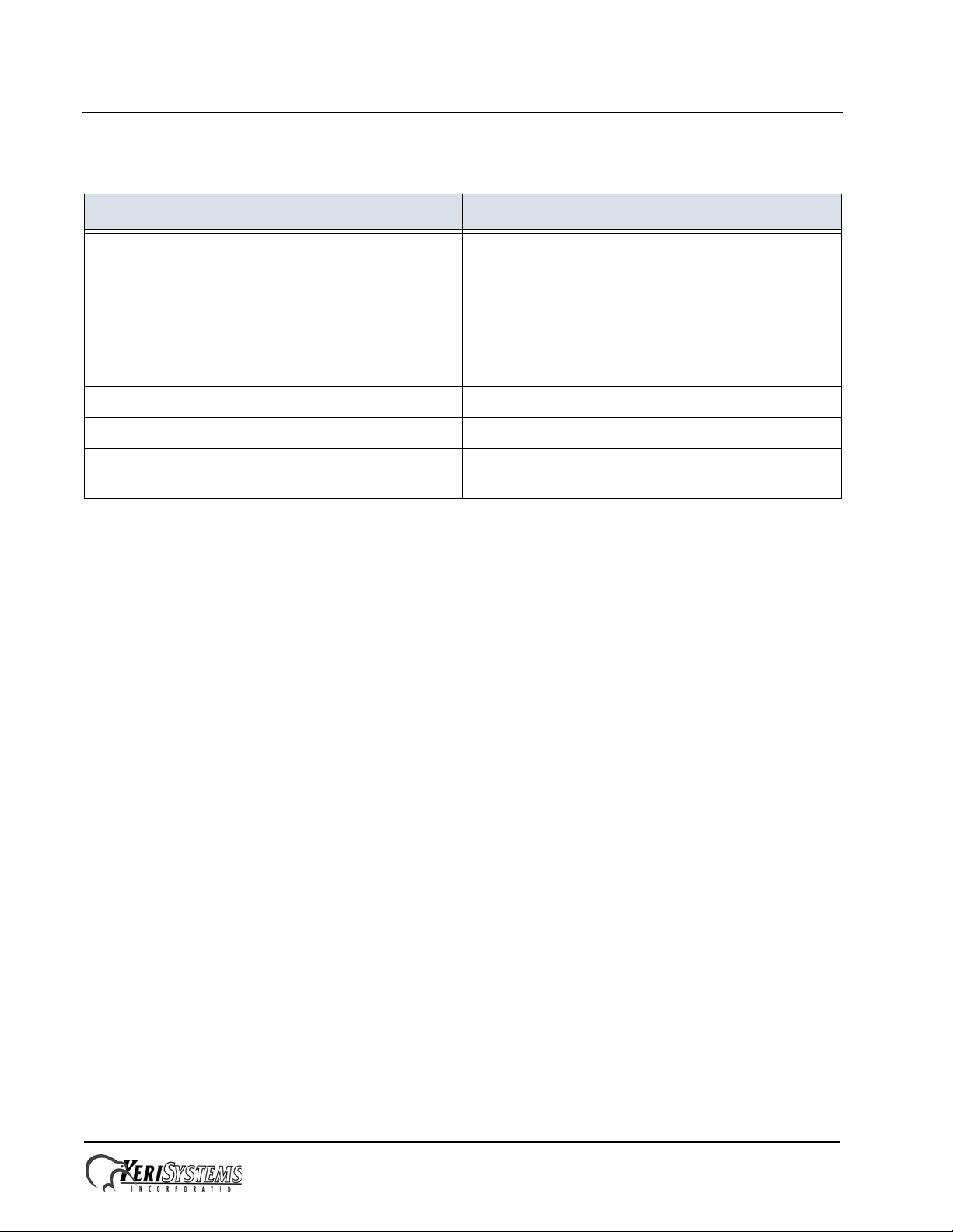
3.0 Contact Keri Systems
Keri USA Keri UK, Ireland, Europe
2305 Bering Drive
San Jose, CA 95131
T elephone: (800) 260-5265
(408) 435-8400
Fax: (408) 577-1792 Fax:+ 44 (0) 1763 274 106
Web: www.kerisys.com Web:www.kerisystems.co.uk
E-mail: sales@kerisys.com
techsupport@kerisys.com
End of document.
Park Farm Industrial Estate
Telephone: + 44 (0) 1763 273 243
E-mail:sales@kerisystems.co.uk
tech-support@kerisystems.co.uk
Unit 17
Ermine Street
Buntingford
Herts SG9 9AZ UK
Page 4 of 4 P/N: 01998-001 Rev. G
 Loading...