

Page 1
MS-3000 MicroStar Reader
The MS-3000 MicroStar Reader
The MS-3000 MicroStar Reader is intended for installation on a window mullion or a door
frame, on or off metal, in proximity applications where an unobtrusive reader is required. The
reader provides an audible beeper and a multi colored LED to annunciate the reader's status
when used with a PXL-250, PXL-100, or IntelliProx.
• Amber - to indicate normal operation awaiting an access event
• Green - to indicate a valid card has been presented or the door has been unlocked for access
• Red - to indicate an invalid card has been presented or the door is in an alarm condition
The MS-3000 MicroStar Reader is housed in a black, weatherproof, shock resistant package.
The reader provides optimum performance when mounted on aluminum; read range is slightly
reduced if the reader is not mounted on aluminum.
1.0 Specifications
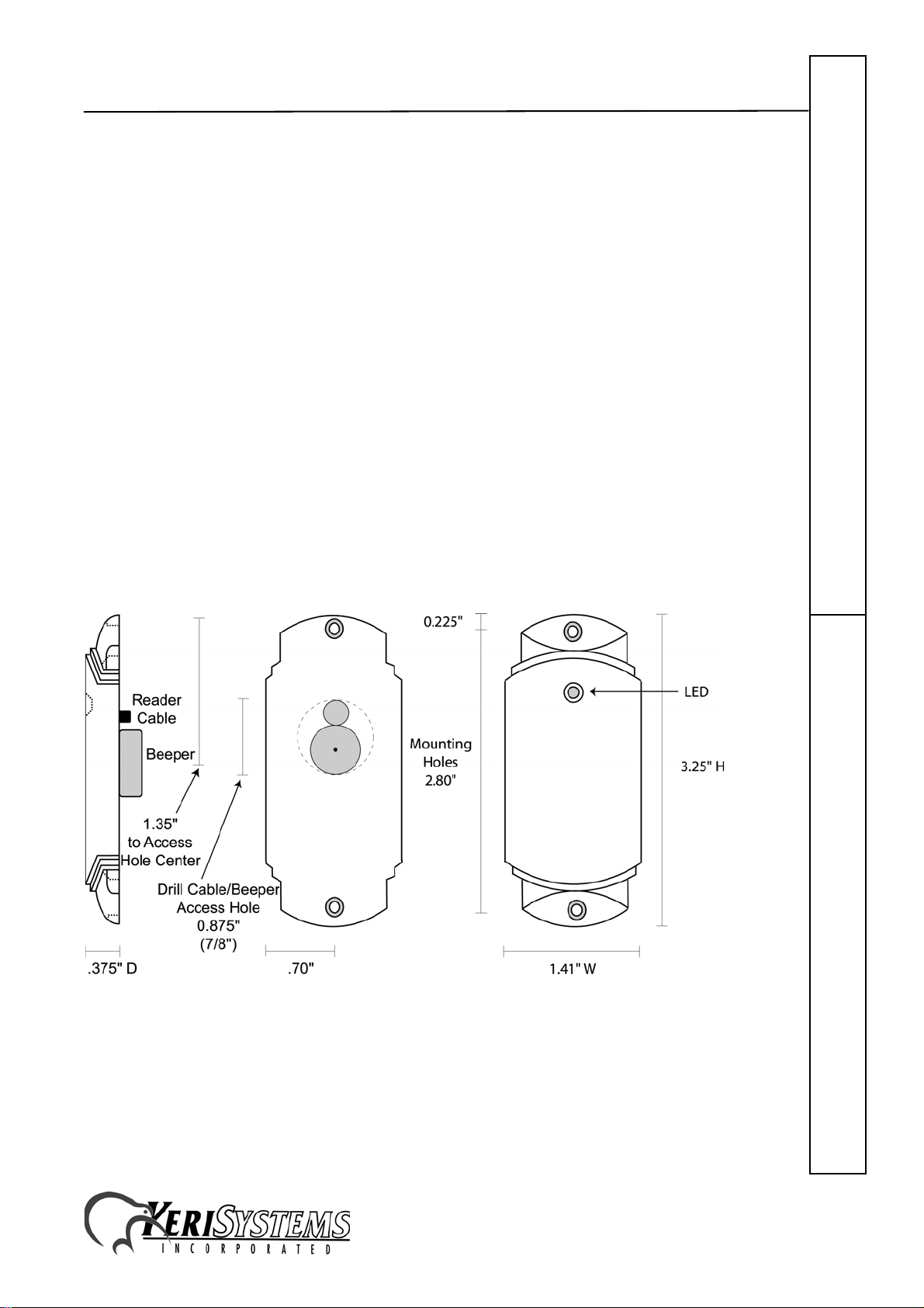
1.1 Dimensions
• 3.25 inches High x 1.41 inches Wide x 0.375 inches Deep
• 8.26 cm High x 3.95 cm Wide x 0.96 cm Deep
Figure 1: MS–3000 Dimensions
MS-3000Quick Start Guide
Unit 17 Park Farm Industrial Estate 01815-001 Rev. H
Buntingford, Herts SG9 9AZ UK
TEL: + 44 (0) 1763 273 243 FAX: + 44 (0) 1763 274 106
Web: www.kerisys.com E-mail: sales@kerisystems.co.uk
Page 1 of 8
Page 2

MS-3000 MicroStar Reader
1.2 Operating Voltage
• 5v to 14v DC @ 50 ma
1.3 Cable Specifications
• up to 500 feet using six conductor, shielded, stranded AWG 24 wire (such as Belden 9536)
2.0 Mounting Instructions
Three holes need to be drilled to mount the MicroStar Reader (see Figure 1). One large hole
(0.875" - 7/8") accommodates the beeper and the reader cable. Two small holes are for
mounting the reader on the mullion or door frame (hole size is dependent upon the size of the
mounting screw).
NOTE: Do not mount the reader near sources of Electromagnetic Interference (EMI) such as a
computer monitor. EMI degrades a reader's read range.
Quick Start GuideMS-3000
Unit 17 Park Farm Industrial Estate 01815-001 Rev. H
Buntingford, Herts SG9 9AZ UK
TEL: + 44 (0) 1763 273 243 FAX: + 44 (0) 1763 274 106
Web: www.kerisys.com E-mail: sales@kerisystems.co.uk Page 2 of 8
Page 3
MS-3000 MicroStar Reader
3.0 Connections
The MicroStar Reader does not require configuration; there are no switches or jumpers to set.
The MicroStar Reader is normally connected to a PXL-250, PXL-100, or IntelliProx, but can be
connected to an alternative host controller/alarm panel through an IntelliProx used in its
Wiegand input device mode. All connections needed to support the reader are made through the
reader's cable. Please consult the tables on pages 2 and 3 for specific connection instructions.
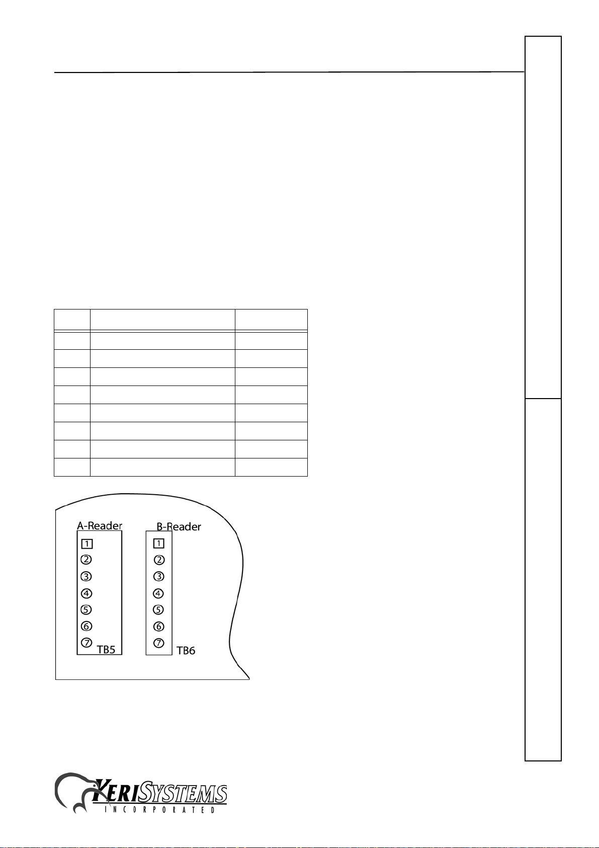
3.1 PXL-250 Connections
The "A" reader connects to TB5, pins 1 through 6 (TB5 has a seventh pin, but no connection is
made to that pin). The "B" reader connects to TB6, pins 1 through 6 (TB6 has a seventh pin, but
no connection is made to that pin).
Connecting to the PXL-250 – TB5 or TB6
Pin # Function Wire Color
1 Reader Antenna Blue
2 Beeper Green
3 Reader Power Red
4 Reader Ground Black
4 Shield Silver
5 Green LED Brown
6 Red LED White
7 no connection –
MS-3000Quick Start Guide
Figure 2: PXL-250 Connections
Unit 17 Park Farm Industrial Estate 01815-001 Rev. H
Buntingford, Herts SG9 9AZ UK
TEL: + 44 (0) 1763 273 243 FAX: + 44 (0) 1763 274 106
Web: www.kerisys.com E-mail: sales@kerisystems.co.uk
Page 3 of 8
Page 4

MS-3000 MicroStar Reader
3.2 Design 5 PXL-100 Connections
The "A" reader connects to TB2, pins 14 through 19. The "B" reader to TB3, pins 20 through
25.
Connecting the PXL-100 – TB2 Connecting to the PXL-100 – TB3
Pin # Function Wire Color Pin # Function Wire Color
14 Green LED Brown 20 Green LED Brown
15 Beeper Green 21 Beeper Green
16 Reader Power Red 22 Reader Power Red
17 Reader Ground Black 23 Reader Ground Black
17 Shield Silver 23 Shield Silver
18 Reader Antenna Blue 24 Reader Antenna Blue
19 Red LED White 25 Red LED White
Quick Start GuideMS-3000
Figure 3: Design 5 PXL-100 Connections
NOTE: Please contact customer support at Keri Systems for information regarding connecting
a Reader to a Design 4 PXL-100. A Design 4 PXL-100 can be identified by the location of its
power connection made at the middle of the left edge of the printed circuit board.
Unit 17 Park Farm Industrial Estate 01815-001 Rev. H
Buntingford, Herts SG9 9AZ UK
TEL: + 44 (0) 1763 273 243 FAX: + 44 (0) 1763 274 106
Web: www.kerisys.com E-mail: sales@kerisystems.co.uk Page 4 of 8
Page 5

MS-3000 MicroStar Reader
3.3 IntelliProx Connections
The reader connects to TB1, pins 1 through 6.
Connecting to the IntelliProx – TB1
Pin # Function Wire Color
1 Reader Antenna Blue
2 Beeper Green
3 Green LED Brown
4 Red LED White
5 Reader Power Red
6 Reader Ground Black
6 Shield Silver
Figure 4: IntelliProx Connections
MS-3000Quick Start Guide
Unit 17 Park Farm Industrial Estate 01815-001 Rev. H
Buntingford, Herts SG9 9AZ UK
TEL: + 44 (0) 1763 273 243 FAX: + 44 (0) 1763 274 106
Web: www.kerisys.com E-mail: sales@kerisystems.co.uk
Page 5 of 8
Page 6

MS-3000 MicroStar Reader
4.0 Installation Verification
The following information applies to an installation with a Keri Systems controller or
IntelliProx unit. When used with an alternative host controller/alarm panel through an
IntelliProx used in its Wiegand input device mode, the actions of the reader's LED and beeper
are controlled by the alternative host controller/alarm panel and might not match those of a Keri
Systems controller.
The reader's power is provided by the controller, so the reader is powered on when the controller
is powered on. The reader's normal state is to display a constantly on Amber LED as it waits for
a card or tag to be presented.
To verify the reader is functioning properly, pass a Keri Proximity Card or a Keri Key Tag
within a few inches of the reader. The reader will beep and either the Green or Red LED will
flash (depending upon whether or not the card/tag has been enrolled at the controller) and then
return to steady Amber.
To verify the reader's read range, hold a Keri Proximity Card or a Keri Key Tag parallel to the
Quick Start GuideMS-3000
reader, about 1 foot away and slowly draw the Card/Tag in toward the reader. Note the distance
when the reader recognizes the card. The MicroStar reader's range will be up to 4 inches for a
card and 2 inches for a tag depending upon the installation conditions, the material on which the
reader is mounted, and whether it is a card or a tag being read. Due to the physical size
difference between cards and tags, tags provide approximately 50% less read range than cards.
Refer to the Troubleshooting the Reader Installation section beginning on page 7 if the reader is
not functioning properly.
Unit 17 Park Farm Industrial Estate 01815-001 Rev. H
Buntingford, Herts SG9 9AZ UK
TEL: + 44 (0) 1763 273 243 FAX: + 44 (0) 1763 274 106
Web: www.kerisys.com E-mail: sales@kerisystems.co.uk Page 6 of 8
Page 7

MS-3000 MicroStar Reader
5.0 Troubleshooting the Reader Installation
Problem Probable Cause Corrective Action
The reader does
not recognize a
card/tag (no
beep, no LED
flash).
1. One or more of the
reader's wiring
connections are
incorrect.
2. The reader is not
receiving proper
power from the
controller.
3. The reader is
mounted too close to
a device that
radiates
electromagnetic
interference.
4. A jumper is not set
correctly on the
controller.
• Power down the controller and verify the
wiring connections are correct for the reader/
controller combination per the instructions
provided in the Connections section on pages
2 and 3.
• Verify the voltage supplied to the reader is
between 5 and 14 VDC.
• Devices such as computer monitors radiate
electromagnetic interference that affects read
range. When possible, relocate either the
reader or the device to provide a greater
distance between the two.
• For a PXL-250: Verify there is a jumper
across pins 1 and 2 of JP4 (refer to the
Technical Reference manual for more
information - Keri p/n 01836-001).
• For a PXL-100: If the controllers are using
TAPTM software, verify JP1 on the controller
and the jumper on the Receiver card1 are
installed across both jumper pins. If the
controllers are using DoorsTM software,
verify JP1 on the controller and the Receiver
a
are not installed across both pins
card
(typically the jumper will be installed onto
one of the pins to keep it available).
• For an IntelliProx: Verify there is not a
jumper across pins 1 and 2 of JP1 (typically
the jumper can be installed onto one of the
pins to keep it available).
5. You are using an
incorrect type of
card.
6. The reader is unable
to read the card.
– continued on next page –
a. The receiver board's jumper is on the underside of the board. Gently pull the receiver board away from
the controller, verify the jumper setting is correct per your application, carefully align the connectors
on the receiver board with the pins on the controller , and gently push the receiver board back into place.
• Make sure you are using an access card that
is compatible with the reader.
• Verify there is nothing that can interfere
between the reader and the access card.
MS-3000Quick Start Guide
Unit 17 Park Farm Industrial Estate 01815-001 Rev. H
Buntingford, Herts SG9 9AZ UK
TEL: + 44 (0) 1763 273 243 FAX: + 44 (0) 1763 274 106
Web: www.kerisys.com E-mail: sales@kerisystems.co.uk
Page 7 of 8
Page 8

MS-3000 MicroStar Reader
Problem Probable Cause Corrective Action
The reader has a
short read range.
Quick Start GuideMS-3000
1. The reader's
controller is not
properly grounded.
2. The shield wire for
the reader's cable
has opened
somewhere between
the reader and the
controller.
3. The reader is
mounted too close to
a device that
radiates
electromagnetic
interference.
4. The controller is
mounted too close to
a device that
radiates
electromagnetic
interference.
• Ensure there is a quality earth ground
connection made to the controller. Refer to
the controller's documentation for specific
information regarding the earth ground
connection.
• Verify the shield line from the controller to
the reader is one continuous, connected line.
Refer to the controller's installation
documentation and verify the shield line is
correctly connected to the controller.
• Devices such as computer monitors radiate
electromagnetic interference that affects read
range. When possible, relocate either the
reader or the device to provide a greater
distance between the two.
• Devices such as computer monitors radiate
electromagnetic interference that affects the
performance of the receiver board on the
controller. When possible, relocate either the
controller or the device to provide a greater
distance between the two.
5. The reader is
powered by a
switching power
supply.
Unit 17 Park Farm Industrial Estate 01815-001 Rev. H
Buntingford, Herts SG9 9AZ UK
TEL: + 44 (0) 1763 273 243 FAX: + 44 (0) 1763 274 106
Web: www.kerisys.com E-mail: sales@kerisystems.co.uk Page 8 of 8
• Switching power supplies are EMI sources.
Change to a linear, regulated power supply.
 Loading...