

Page 1
OPERATOR’S MANUAL
TMA VXI-27
plug & play POWER MODULE CONTROLLER
INTERACTIVE DIGITALLY CONTROLLED
POWER MODULE SYSTEM
KEPCO INC.
An ISO 9001 Company.
plug & play POWER MODULE
MODEL
TMA VXI-27
CONTROLLER
ORDER NO. REV. NO.
IMPORTANT NOTES:
1) This manual is valid for the following Model and associated serial numbers:
MODEL SERIAL NO. REV. NO.
2) A Change Page may be included at the end of the manual. All applicable changes and
revision number changes are documented with reference to the equipment serial numbers. Before using this Instruction Manual, check your equipment serial number to identify
your model. If in doubt, contact your nearest Kepco Representative, or the Kepco Documentation Office in New York, (718) 461-7000, requesting the correct revision for your particular model and serial number.
3) The contents of this manual are protected by copyright. Reproduction of any part can be
made only with the specific written permission of Kepco, Inc.
Data subject to change without notice.
KEPCO®
©2007, KEPCO, INC
P/N 243-0886R8a
KEPCO, INC. z 131-38 SANFORD AVENUE z FLUSHING, NY. 11352 U.S.A. z TEL (718) 461-7000 z FAX (718) 767-1102
email: hq@kepcopower.com z World Wide Web: http://www.kepcopower.com
THE POWER SUPPLIER™
Page 2

Page 3

TABLE OF CONTENTS
SECTION PAGE
SECTION 1 - INTRODUCTION
1.1 Scope of Manual ..................................................................................................................................... 1-1
1.2 General Description................................................................................................................................. 1-1
1.3 Specifications ......................................................................................................................................... 1-2
1.4 TMA VXI-27 Interconnections ................................................................................................................. 1-2
1.5 Accessories ............................................................................................................................................. 1-3
SECTION 2 - INSTALLATION
2.1 Unpacking and Inspection ....................................................................................................................... 2-1
2.2 Installation ............................................................................................................................................... 2-1
2.2.1 VXI Address Select............................................................................................................................ 2-1
2.3 Front Panel Terminations ........................................................................................................................ 2-1
SECTION 3 - OPERATION
3.1 Local Operation....................................................................................................................................... 3-1
3.1.1 Front panel indicators ........................................................................................................................ 3-1
3.1.2 Auxiliary Signals ................................................................................................................................ 3-1
3.1.2.1 Emergency Output Shutdown...................................................................................................... 3-1
3.1.2.2 Discrete Fault Line....................................................................................................................... 3-1
3.1.2.3 +5V Output................................................................................................................................... 3-2
3.2 Remote Operation................................................................................................................................... 3-2
3.3 VXI
3.3.1 Background........................................................................................................................................ 3-2
3.3.2 Driver Installation ............................................................................................................................... 3-2
3.3.3 Operating the Soft Panel ................................................................................................................... 3-3
3.3.3.1 Understanding the Controls. ........................................................................................................ 3-4
3.3.3.2 Select the Channel....................................................................................................................... 3-6
3.3.3.3 Set the Voltage/current................................................................................................................ 3-6
3.3.3.4 Apply Programmed Settings to the Power Supply....................................................................... 3-6
3.3.3.5 Enable the Power Supply Output................................................................................................. 3-6
3.4 VXIbus Communication........................................................................................................................... 3-6
3.4.1 Typical VXIbus Start-up Sequence.................................................................................................... 3-8
3.5 SCPI Programming ................................................................................................................................. 3-8
3.5.1 SCPI Messages................................................................................................................................. 3-8
3.5.2 Common Commands/Queries ........................................................................................................... 3-9
3.5.3 SCPI Subsystem Command/Query Structure.................................................................................... 3-9
3.5.4 Program Message Structure.............................................................................................................. 3-10
3.5.4.1 Keyword....................................................................................................................................... 3-11
3.5.4.2 Keyword Separator ...................................................................................................................... 3-12
3.5.4.3 Query Indicator ............................................................................................................................ 3-12
3.5.4.4 Data ............................................................................................................................................. 3-12
3.5.4.5 Data Separator............................................................................................................................. 3-12
3.5.4.6 Message Unit Separator.............................................................................................................. 3-12
3.5.4.7 Root Specifier .............................................................................................................................. 3-12
3.5.4.8 Message Terminator.................................................................................................................... 3-13
3.5.5 Understanding The Command Structure........................................................................................... 3-13
3.5.6 Addressing Multiple Power Supplies ................................................................................................. 3-14
3.5.7 Understanding The Command Structure........................................................................................... 3-14
3.5.8 Program Message Syntax Summary................................................................................................. 3-15
3.5.9 Status Reporting................................................................................................................................ 3-15
3.5.9.1 STATUS REPORTING STRUCTURE ......................................................................................... 3-16
3.5.9.2 Operational Status Register......................................................................................................... 3-16
3.5.9.3 QUEStionable Status Register..................................................................................................... 3-16
3.5.9.4 Multiple Logical Instruments ........................................................................................................ 3-18
3.5.10 Program Example.............................................................................................................................. 3-19
3.6 CIIL Programming ................................................................................................................................... 3-19
plug&play
Operation........................................................................................................................ 3-2
TMA VXI-27 SVC 101602
i
Page 4

TABLE OF CONTENTS
SECTION PAGE
3.7 Calibration............................................................................................................................................... 3-19
3.8 Maintenance ........................................................................................................................................... 3-19
APPENDIX A - MS WINDOWS HELP FILES
A-1 Soft Front Panel...................................................................................................................................... 1
A.1.1 Soft Front Panel Overview ............................................................................................................... A-1
A.1.2 Soft Front Panel Controls................................................................................................................. A-1
A.1.2.1 Init ............................................................................................................................................... A-1
A.1.2.2 Channel....................................................................................................................................... A-1
A.1.2.3 Voltage ........................................................................................................................................ A-1
A.1.2.4 Current ........................................................................................................................................ A-1
A.1.2.5 Mode ........................................................................................................................................... A-1
A.1.2.6 Output ......................................................................................................................................... A-1
A.1.2.7 Polarity ........................................................................................................................................ A-1
A.1.2.8 Sys Reset.................................................................................................................................... A-2
A.1.2.9 Chan Reset ................................................................................................................................. A-2
A.1.2.10 Test ............................................................................................................................................. A-2
A-2 LabView Library...................................................................................................................................... 2
A.2.1 LabView Library Overview ................................................................................................................ A-2
A.2.1.1 Instr handle in.............................................................................................................................. A-2
A.2.1.2 Instr handle out ........................................................................................................................... A-2
A.2.1.3 Error in ........................................................................................................................................ A-2
A.2.1.4 Error out ...................................................................................................................................... A-2
A.2.2 LabView Library Functions................................................................................................................ A-3
A.2.2.1 About........................................................................................................................................... A-3
A.2.2.2 AutoCon ...................................................................................................................................... A-3
A.2.2.3 Chanl........................................................................................................................................... A-3
A.2.2.4 Close ........................................................................................................................................... A-3
A.2.2.5 GetStatus .................................................................................................................................... A-3
A.2.2.6 Initialize ....................................................................................................................................... A-4
A.2.2.7 Mode ........................................................................................................................................... A-4
A.2.2.8 Outp ............................................................................................................................................ A-4
A.2.2.9 Read............................................................................................................................................ A-4
A.2.2.10 Reset ........................................................................................................................................... A-5
A.2.2.11 RevisionQuery............................................................................................................................. A-5
A.2.2.12 SelfTest ....................................................................................................................................... A-5
A.2.2.13 Set ............................................................................................................................................... A-5
A.2.2.14 Vers ............................................................................................................................................. A-6
A-6 Knowledge Base..................................................................................................................................... 6
APPENDIX B - SCPI COMMON COMMAND/QUERY DEFINITIONS
B.1 Introduction ............................................................................................................................................. B-1
B.2 *CLS — Clear Status Command .......................................................................................................... B-1
B.3 *ESE — Standard Event Status Enable Command................................................................................ B-1
B.4 *ESE? — Standard Event Status Enable Query..................................................................................... B-1
B.5 *ESR? — Event Status Register Query................................................................................................. B-2
B.6 *IDN? — Identification Query.................................................................................................................. B-2
B.7 *OPC — Operation Complete Command ............................................................................................... B-2
B.8 *OPC? — Operation Complete Query.................................................................................................... B-2
B.9 *OPT? — Options Query ........................................................................................................................ B-3
B.10 *RST — Reset Command....................................................................................................................... B-3
B.11 *SRE — Service Request Enable Command ........................................................................................ B-4
B.12 *SRE? — Service Request Enable Query .............................................................................................. B-4
B.13 *STB? — Status Byte Register Query ................................................................................................... B-4
ii
TMA VXI-27 SVC 101602
Page 5

TABLE OF CONTENTS
SECTION PAGE
B.14 *TRG — Trigger Command................................................................................................................... B-4
B.15 *TST? — Self Test Query....................................................................................................................... B-4
B.16 *WAI — Wait-to-Continue Command ..................................................................................................... B-5
APPENDIX C - SCPI COMMAND/QUERY DEFINITIONS
C.1 Introduction............................................................................................................................................. C-1
C.2 INITiate[:IMMediate] Command ............................................................................................................. C-1
C.3 INITiate:CONTinuous Command ........................................................................................................... C-1
C.4 INITiate:CONTinuous Query .................................................................................................................. C-2
C.5 INSTrument:CATalog Query .................................................................................................................. C-2
C.6 INSTrument[:NSELect] Command ......................................................................................................... C-2
C.7 INSTrument[:SELect] Command............................................................................................................ C-2
C.8 INSTrument[:SELect]? Query................................................................................................................. C-3
C.9 INSTrument:STATe Command .............................................................................................................. C-3
C.10 MEASure[:SCALar]:CURRent[:DC]? Query ........................................................................................... C-3
C.11 MEASure[:VOLTage][:SCALar][:DC]? Query......................................................................................... C-3
C.12 OUTPut[:STATe] Command................................................................................................................... C-4
C.13 OUTPut[:STATe] Query ......................................................................................................................... C-4
C.14 [SOURce:]CURRent[:LEVel][:IMMediate][:AMPlitude] Command.......................................................... C-4
C.15 [SOURce:]CURRent[:LEVel][:IMMediate][:AMPlitude] Query ................................................................ C-4
C.16 [SOURce:]CURRent:[:LEVel]TRIGgered[:AMPlitude] Command........................................................... C-5
C.17 [SOURce:]CURRent:[:LEVel]TRIGgered[:AMPlitude]? Query ............................................................... C-5
C.18 [SOURce:]VOLTage[:LEVel][:IMMediate][:AMPlitude] Command.......................................................... C-6
C.19 [SOURce:]VOLTage[:LEVel][:IMMediate][:AMPlitude]? Query .............................................................. C-6
C.20 [SOURce:]VOLTage:[:LEVel]TRIGgered[:AMPlitude] Command........................................................... C-6
C.21 [SOURce:]VOLTage:[:LEVel]TRIGgered[:AMPlitude]? Query ............................................................... C-6
C.22 [SOURce:]FUNCtion:MODE Command ................................................................................................. C-7
C.23 STATus:OPERation:CONDition Query................................................................................................... C-7
C.24 STATus:OPEReration:ENABle Command ............................................................................................. C-7
C.25 STATus:OPEReration:ENABle? Query.................................................................................................. C-7
C.26 STATus:OPERation[:EVENt] Query....................................................................................................... C-7
C.27 STATus:PRESet Command ................................................................................................................... C-8
C.28 STATus:QUEStionable[:EVENt]? Query ................................................................................................ C-8
C.29 STATus:QUEStionable:CONDition? Query............................................................................................ C-9
C.30 STATus:QUEStionable:ENABle Command............................................................................................ C-9
C.31 STATus:QUEStionable:ENABle? Query ................................................................................................ C-9
C.32 STATus:QUEStionable:INSTrument? Query.......................................................................................... C-9
C.33 STATus:QUEStionable:INSTrument1? Query........................................................................................ C-10
C.34 STATus:QUEStionable:INSTrument2? Query........................................................................................ C-10
C.35 STATus:QUEStionable:INSTrument:ENABle Command....................................................................... C-10
C.36 STATus:QUEStionable:INSTrument:ENABle Query.............................................................................. C-11
C.37 STATus:QUEStionable:INSTrument1:ENABle Command ..................................................................... C-11
C.38 STATus:QUEStionable:INSTrument1:ENABle? Query .......................................................................... C-11
C.39 STATus:QUEStionable:INSTrument2:ENABle Command ..................................................................... C-11
C.40 STATus:QUEStionable:INSTrument2:ENABle? Query .......................................................................... C-11
C.41 STATus:QUEStionable:INSTrument:ISUM Query.................................................................................. C-11
C.42 STATus:QUEStionable:INSTrument:ISUM:ENABle Command ............................................................. C-11
C.43 STATus:QUEStionable:INSTrument:ISUM:ENABle? Query .................................................................. C-12
C.44 SYSTem:ERRor[:NEXT]? Query............................................................................................................ C-12
C.45 SYSTem:ERRor:CODE? Query ............................................................................................................. C-12
C.46 SYSTem:ERRor:CODE:ALL? Query...................................................................................................... C-12
C.47 SYSTem:LANGuage Command............................................................................................................. C-12
C.48 SYSTem:SET Command ....................................................................................................................... C-13
C.49 SYSTem:VERSion Query....................................................................................................................... C-13
TMA VXI-27 SVC 101602
iii
Page 6

TABLE OF CONTENTS
SECTION PAGE
APPENDIX D - CIIL COMMAND DEFINITIONS
D-1 Introduction ............................................................................................................................................. 1
APPENDIX E - GLOSSARY OF VXI TERMS
E-1 Introduction............................................................................................................................................. 1
APPENDIX F - SAMPLE PROGRAM
F-1 Introduction ............................................................................................................................................. 1
F-1 Description.............................................................................................................................................. 1
iv
TMA VXI-27 SVC 101602
Page 7

LIST OF FIGURES
FIGURE TITLE PAGE
1-1 Remotely Controlled Power Supply Configurations Using Kepco Products................................................ viii
1-2 Typical Controller to Power Module Interface ............................................................................................. 1-3
1-3 Mechanical Outline Drawing ....................................................................................................................... 1-4
2-1 VXI Address Select..................................................................................................................................... 2-2
2-2 TMA VXI-27 Front Panel............................................................................................................................. 2-3
3-1 TMA VXI-27 plug&play Directory Structure................................................................................................. 3-3
3-2 TMA VXI-27
3-3 TMA VXI-27 plag&pla
3-4 Tree Diagram of SCPI Commands Used with TMA VXI-27 Controller ....................................................... 3-9
3-5 Message Structure...................................................................................................................................... 3-11
3-6 Status Reporting Structure.......................................................................................................................... 3-17
3-7 Expansion of QUEStionable Register for Multiple Logical Instruments ...................................................... 3-19
B-1 GPIB Commands ....................................................................................................................................... B-3
B-2 Using the *WAIt-to-continue Command ..................................................................................................... B-5
C-1 Use of INSTrument:CATalog Query .......................................................................................................... C-2
C-2 Identifying and Selecting Devices on BITBUS ........................................................................................... C-3
C-3 Programming the Output............................................................................................................................ C-5
C-4 Programming Current ................................................................................................................................ C-6
C-5 Using Status Commands and Queries....................................................................................................... C-8
D-1 FNC — Function Command....................................................................................................................... D-1
D-2 INX — Initiate Op Code Command............................................................................................................ D-2
D-3 FTH — Fetch Command............................................................................................................................ D-2
D-4 SET Command .......................................................................................................................................... D-3
D-5 OPN, CLS — Open, Close Relay Commands ........................................................................................... D-4
D-6 RST — Reset Command ........................................................................................................................... D-4
D-7 CNF, IST — Confidence Test, Internal Self Test Commands.................................................................... D-4
D-8 STA — Status Command........................................................................................................................... D-5
D-9 GAL — Go to Alternate Language Command .......................................................................................... D-6
plug&play Controller Selection ............................................................................................... 3-3
y
panel...................................................................................................................... 3-4
TMA VXI-27 101602
v/(vi Blank)
Page 8

LIST OF TABLES
TABLE TITLE PAGE
1-1 Specifications ..............................................................................................................................................1-2
1-2 Accessories .................................................................................................................................................1-3
2-1 Input/output Pin Assignments .....................................................................................................................2-3
3-1 Plug&play Panel Controls and Indicators ....................................................................................................3-4
3-2 VXI Bus Commands ....................................................................................................................................3-6
3-3 SCPI Command Index ................................................................................................................................3-10
3-4 Rules Governing Shortform Keywords ........................................................................................................3-11
B-1 IEEE 488.2 Command/query Index ........................................................................................................... B-1
B-2 Standard Event Status Enable Register and Standard Event Status Register Bits ................................... B-1
B-3 Service Request Enable and Status Byte Register Bits ............................................................................. B-4
C-1 SCPI Subsystem Command/query Index ..................................................................................................C-1
C-2 Operation Condition Register, Operation Enable Register,
and Operation Event Register Bits ..........................................................................................................C-7
C-3 Questionable Event Register, Questionable Condition Register
and Questionable Condition Enable Register Bits ..................................................................................C-9
C-4 Questionable Instrument Register 0 Bits ................................................................................................... C-10
C-5 Questionable Instrument Register 1 Bits ................................................................................................... C-10
C-6 Questionable Instrument Register 2 Bits ................................................................................................... C-10
C-7 Error Messages ..........................................................................................................................................C-13
D-1 CIIL Subsystem Command/query Index ....................................................................................................D-1
D-2 CIIL Error Messages ..................................................................................................................................D-5
D-3 CIIL Error Handling Utility Commands .......................................................................................................D-6
TMA VXI -27 101602
vii
Page 9
FIGURE 1-1. REMOTELY CONTROLLED POWER SUPPLY CONFIGURATIONS USING KEPCO PRODUCTS
viii
TMA VXI -27 101602
Page 10

1.1 SCOPE OF MANUAL
This service manual contains the specifications and instructions for the installation and operation of the Model TMA VXI-27 Power Module Controller, manufactured by Kepco, Inc. Flushing,
N.Y. U.S.A. A parts list and schematic diagrams are located in Section 4
1.2 GENERAL DESCRIPTION
The Kepco model TMA VXI-27 is a Power Module Controller which plugs into a VXI computer
chassis and allows the user to program a VXI computer to control and monitor the outputs of up
to 27 Kepco power modules (such as “MAT”s, “MBT”'s, “MST”s and “BOP”s) equipped for communication via the IEEE 1118 two-wire serial bus (see Figure 1-1). The IEEE 1118 two-wire
serial bus, also referred to as the Control Bus, allows the TMA VXI-27 to communicate with the
27 power modules up to a maximum distance of 1000 feet (300 meters).
The TMA VXI-27 includes plug&play software drivers which greatly simplify programming of the
power supplies connected to the IEEE 1118 serial bus. This is accomplished through a “soft
panel,” a virtual panel that gives the operator access to power supply operating controls and
indicators, allowing power supply operation by clicking a mouse on the virtual control, and
observing power supply indicators and measured values on a computer monitor.
The TMA VXI-27 communicates with the VXI computer via the VXIbus (an abbreviation for
“VMEbus eXtensions for Instrumentation”) which is based on the worldwide VMEbus standard
(IEEE STD 1014). The VXI backplane includes the 32-bit VME computer bus as well as
high-performance instrumentation buses for precision timing and synchronization between
instrument components. (See Appendix E for a Glossary of VXI terms.)
SECTION 1 - INTRODUCTION
The TMA VXI-27 is a Message Based VXI servant interface with Programmable Interrupter
capabilities for Event generation, conforming to Specification VXI-1, REV. 1.4. As a Message
Based Device it implements all Word Serial Commands required for an I4 class (IEEE 488 compatible) Instrument (see Table 2-1). It is a Single Width C sized card.
The TMA VXI-27 communicates through the VXI backplane with the Resource Manager (Slot 0
Controller) using commands in either the default language, SCPI (Standard Commands for Programmable Instruments) commands (default), or CIIL (Control Interface Intermediate Language), the alternate language. The VXI Resource Manager, known as the Slot 0 Controller, is a
common resource system module containing the VMEbus Resource Manager and VMEbus
System Controller. The Resource Manager provides configuration management services, commander/servant mapping, self test and diagnostics.
The VXI Slot 0 Controller can set the output voltage with current limit, or the output current with
voltage limit of any one of the 27 KEPCO Power Supplies interconnected through the Control
Bus to the TMA VXI-27. It can then program the TMA VXI-27 to read back (through the Control
Bus) the actual output voltage and current delivered by each of the power modules to their
respective loads. The TMA VXI-27 continually polls all of the power modules on the Control Bus
for error flags. All data transmissions between the Slot 0 Controller and the TMA VXI-27 are
ASCII encoded. The values for the command parameters can be written in integer, decimal or
scientific notation.
TMA VXI-27 101602
1-1
Page 11

1.3 SPECIFICATIONS (SEE TABLE 1-1)
TABLE 1-1. SPECIFICATIONS
SPECIFICATION DESCRIPTION
Device Type Message-based
Device Substates Initialize, Configure, Normal Operation
Applicable
VXI Commands
Addresses Static, configurable between 1 and 254 using DIP switch (see PAR. 2.2.1).
Manufacturer ID 380410, (0EDCH), read from register 0
Address Space A16, normal handshake only
Programmable Interrupt Generates Request True or Request False events
Interrupt Priority
Capabilities
Input Power Requirement Approximately 2A from +5V backplane of VXI.
Physical Dimensions See Outline Drawing, Figure 1-3.
See Table 3-2.
Software assigned (via Slot 0 Controller) from 0 to 7;
0 = no interrupt (default),1 = highest priority, 7 = lowest priority
Message-based Device with Word Serial Capabilities; VXIbus Instrument Protocol;
I4 Class VXI Instrument
1.4 TMA VXI-27 INTERCONNECTIONS
A shielded two (2) wire twisted-pair cable equipped with a 9 pin D-type, male, plug-in connector
(supplied) is used to connect the TMA VXI-27 with the power modules. Input power and input/
output signals are provided through the VXI backplane (see Figure 1-2).
An opto-isolated, active high or non-isolated, active low, emergency shutdown input is provided
on the 15 pin D-type female connector located on the front pane (see PAR. 3.1.2.1)l. On the
same connector 2 additional lines provide a normally open contact indicating the proper functioning of the internal microsystem (Discrete Fault line). If either a serious malfunction or a catastrophic error occurs, the contacts will close (see PAR. 3.1.2.2)
FIGURE 1-1.
1-2
In configurations where power modules are daisy chained on the IEEE 1118 control bus (see
Figure 1-2), the last power module control bus outlet (in the daisy chain) must be terminated
with the IEEE Control Bus Terminator supplied with the controller to reduce spurious noise and
provide proper impedance matching. The terminator supplied is a 9-pin, D-type connector; for
Kepco MAT Power Supplies with a round 5 pin connector use the 5 pin terminator listed in Table
1-2.
TMA VXI-27 101602
Page 12
.
FIGURE 1-2. TYPICAL CONTROLLER TO POWER MODULE INTERFACE
1.5 ACC ESSORIES
Table 1-2 lists the accessories for the TMA VXI-27 Controller.
TABLE 1-2. ACCESSORIES
ACCESSORY PART NUMBER USE NOTE
Cable - two 9-pin connectors, ~ 6 ft. (2 m)
15 -Pin
Connector
Hood 108-0204
(Amphenol P/N 17-2588-6)
Snap-in 107-0187
Terminator, 9-pin 195-0086 Terminate IEEE 1118 bus daisy chain Supplied
Terminator,
5-pin
Cable - two 5-pin connectors
Cable - one 5-pin and one 9pin connector, ~6 ft. (2 m)
118-0844
142-0276
(Amp P/N 205206-1)
(Amp P/N 66504-2)
195-0075 Terminate IEEE 1118 bus daisy chain (for MAT
118-0699
118-0749 Daisy chain TMA VXI-27 and Kepco Power Supplies
Daisy chain TMA 4882-27and Kepco Power Supplies with 9-pin connector on IEEE 1118 bus.
Mating Connector for AUXILIARY SIGNALS connector
Used with 15-Pin Connector Supplied
Used with 15-Pin Connector Supplied
power supply with 5 pin round connector)
Daisy chain Kepco Power Supplies with 5-pin con-
nectors on IEEE 1118 bus.
with 5-pin connector on IEEE 1118 bus.
Supplied
Supplied
Not
supplied
Not
supplied
Not
supplied
Cable - one 5-pin and one 9pin connector, ~12 ft. (4 m)
Cable - two 9-pin connectors, ~ 12 ft. (4 m)
TMA VXI-27 040507 1-3
118-0852
118-0853
Daisy chain TMA VXI-27and Kepco Power Supplies
with 5-pin connector on IEEE 1118 bus.
Daisy chain TMA VXI-27and Kepco Power Supplies
with 9-pin connector on IEEE 1118 bus.
Not
supplied
Not
supplied
Page 13
FIGURE 1-3. MECHANICAL OUTLINE DRAWING
1-4
TMA VXI-27 101602
Page 14

SECTION 2 - INSTALLATION
2.1 UNPACKING AND INSPECTION
The Model TMA VXI-27 has been carefully inspected and tested prior to packing. Inspect the
shipping carton immediately upon receipt for evidence of damage during transit. Save the original packing material. If any indication of damage is found file a claim immediately with the
responsible transport service.
For repairs of a product damaged in shipment, contact the Kepco Factory Representative
nearest you or the Kepco Customer Service Department directly for further instruction.
2.2 INSTALLATION
The installation and setup procedure for the TMA VXI-27 consists of the following steps:
1. Set the VXI Address Selector (PAR. 2.2.1)
2. Select an empty slot in the C size VXI chassis and remove the slot cover plate.
3. Turn off the power if it is on and slide the TMA VXI-27 module into the chassis with the
LEDs up (or to the left in the case of a horizontal chassis). Secure TMA VXI-27 to chassis
with self-retaining screws at the top and bottom of the front panel
4. Connect the 9 pin D-type connector located on the front panel to the power modules
through the Control Bus in a daisy chain configuration using the control bus cable supplied
(see Figure 1-2). For installations that exceed the length of the control bus cable supplied,
refer to Table 1-2 for cable specifications; the maximum cable length is 300 meters (1000
feet).
5. Connect Terminator (supplied) to last IEEE 1118 control bus connector in daisy chain (see
Figure 1-2). (For Kepco MAT power supplies with 5-pin round connector, use terminator P/
N 195-0075; see Table 1-2.)
NOTE: Terminator must be used even if only one power supply is connected to the Controller
to ensure reduction of spurious noise and proper impedance matching.
6. To use the AUX. SIGNALS connector refer to PAR. 3.1.2 for a description of the available
signals and PAR. 2.3 for connector type and pin assignments.
7. Connect all power module outputs to their respective loads.
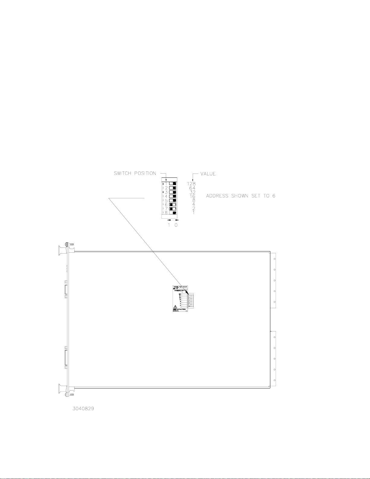
2.2.1 VXI ADDRESS SELECT
Set the VXI address selector to an unused VXI address between 1 and 254 using DIP
switches accessible through the right shield as shown in Figure 2-1. The TMA VXI-27 address
is preset to the factory default address of 6.
2.3 FRONT PANEL TERMINATIONS (SEE FIGURE 2-2.)
a. IEEE 1118 (Control Bus) connector. Connections to the control bus are made through the
IEEE 1118 connector, a 9 pin D-type female receptacle. Refer to Table 2-1 for pin assignments.
TMA VXI -27 101602
2-1
Page 15
b. Auxiliary Signals connector. This is a 15 pin D-type female receptacle. Refer to Table 2-1 for
pin assignments.
The DISCRETE FAULT LINE relay has the contacts open if the internal microsystem is
functioning normal by monitoring a pulse generated in the timer interrupt routine. If the microsystem is not functioning normally or a catastrophic condition appears on one of the power modules the contacts will close and then reopen when the catastrophic condition disappears and the
error buffer has been read (if the Command Language is CIIL) or when the Device Dependent
Error from the Event Status Register has been read (if the Command Language is SCPI).
The ISOLATED and NON ISOLATED EMERGENCY SHUT-DOWN INPUTS activates the
non-maskable interrupt of the microsystem forcing the microsystem to send a reset to all
KEPCO power supplies.
2-2
FIGURE 2-1. VXI ADDRESS SELECT
TMA VXI -27 101602
Page 16
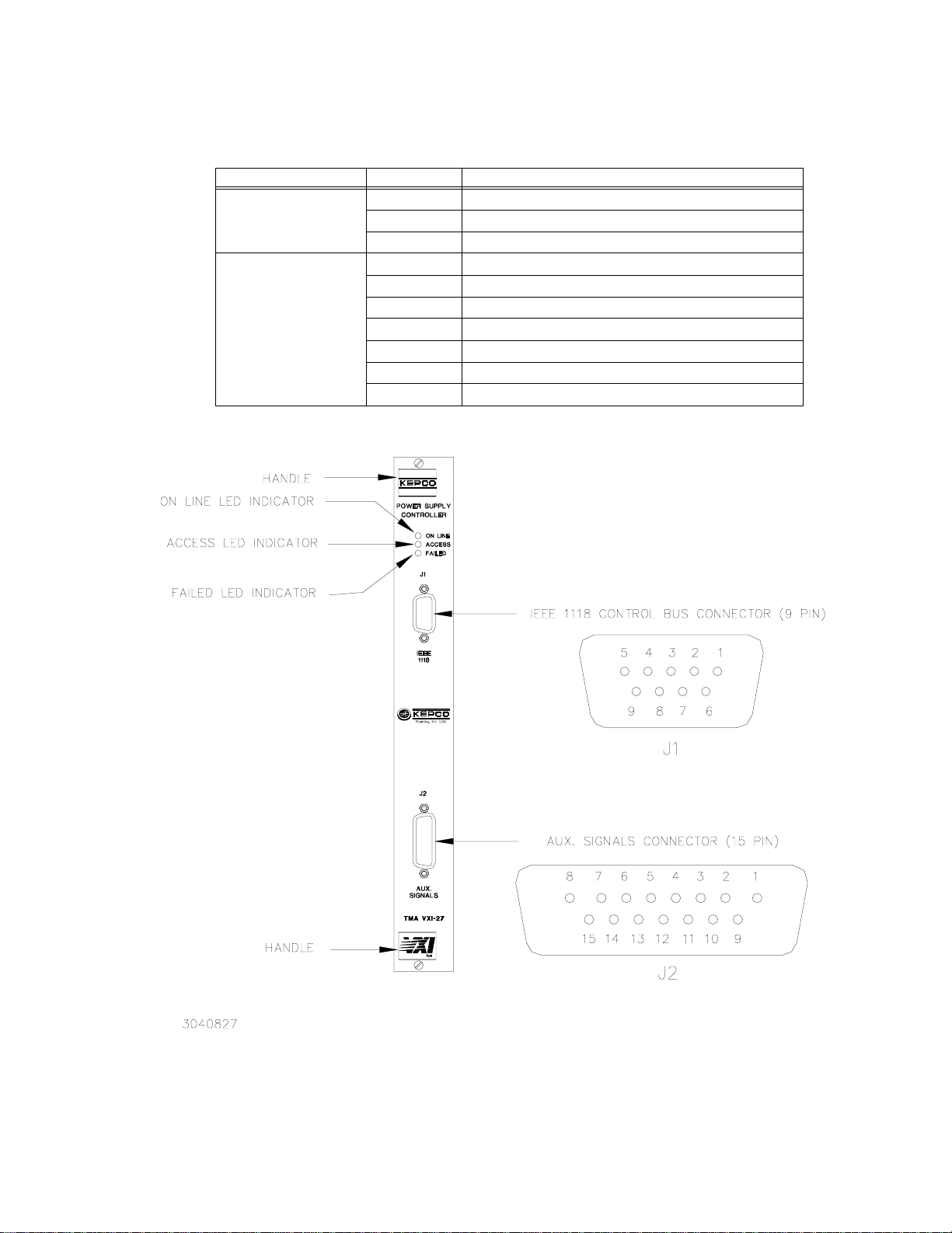
TABLE 2-1. INPUT/OUTPUT PIN ASSIGNMENTS
CONNECTOR PIN FUNCTION
IEEE 1118
(9-Pin, D-type, female)
AUX. SIGNALS
(15-Pin, D-type, female)
1, 2, 6, 7 Ground
3, 4, 5 IEEE 1118 (2-Wire Differential Interface)
8, 9 IEEE 1118 (2-Wire Differential Interface)
1, 7. 8 Emergency Shut-down - Isolated Input Cathode (–)
2, 5, 6 Emergency Shut-down - Isolated Input Anode (+)
3, 4 +5v Output (Through 390 Ohm)
9, 11 Ground
10 Emergency Shut-down Input - Non Isolated
12, 13 Discrete Fault Line - Relay Contact Pin 1
14, 15 Discrete Fault Line - Relay Contact Pin 2
TMA VXI -27 101602
FIGURE 2-2. TMA VXI-27 FRONT PANEL
2-3/(2-4 Blank)
Page 17

Page 18

SECTION 3 - OPERATION
3.1 LOCAL OPERATION
There is no local operation of the TMA VXI-27 controller; however, the controller provides three
front panel LEDs (see PAR. 3.1.1) and three auxiliary functions (see PAR.3.1.2) to the user in
addition to the remote programming capability described in PAR.’s 3.2 through 3.5.
3.1.1 FRONT PANEL INDICATORS
The TMA VXI-27 is equipped with 3 front panel LEDs which have the following functions: (see
Figure 2-2)
a. ONLINE. The top LED (for vertically mounted unit), green colored, indicates that the power is
applied and the internal microsystem is ON LINE. It is turned ON by an output port instruction executed by the internal microprocessor.
b. ACCESS. The middle position LED, green colored, indicates that a VXI ACCESS cycle to
address the module has been executed.
c. FAILED. The bottom LED (for vertically mounted unit), red colored, indicates the FAILED
condition. It is on during the power-up self test which is executed by the module every time
the power is first applied or after a hardware reset. The VXI standard requires that this LED
go off within 5 seconds. If this LED is still ON after 5 seconds, the VXI module is defective
and has to be serviced.
3.1.2 AUXILIARY SIGNALS
The AUX SIGNALS connector (see Table 2-1 and Figure 2-2) at the front panel provides the following auxiliary functions: emergency output shutdown, discrete fault, and +5V output.
3.1.2.1 EMERGENCY OUTPUT SHUTDOWN
The emergency output shutdown function allows the user to reset all the power modules connected to the Control Bus with a single discrete signal. A user-initiated emergency shutdown
activates the non-maskable interrupt of the microsystem, forcing the microsystem to send a
reset to all power modules connected to the Control Bus. The NON-ISOLATED EMERGENCY
SHUT-DOWN INPUT accepts a TTL input signal to initiate shutdown; this signal is referred to
signal common. The ISOLATED EMERGENCY SHUT-DOWN INPUT requires a 2-wire isolated
signal and return path.
3.1.2.2 DISCRETE FAULT LINE
The DISCRETE FAULT LINE function provides a discrete controller fault indication by means of
an internal relay. The DISCRETE FAULT LINE relay contacts are open (open circuit between
DISCRETE FAULT LINE PIN 1 and PIN 2) if the internal microsystem is functioning normally;
this is accomplished by monitoring a pulse generated in the timer interrupt routine. If the microsystem is not functioning normally, or a catastrophic condition appears on one of the power
modules, the contacts will close. The contacts reopen when the catastrophic condition disappears and either the error buffer has been read (if the Command Language is CIIL) or when the
Device Dependent Error from the Event Status Register has been read (if the Command Language is SCPI).
TMA VXI -27 101602
3-1
Page 19

3.1.2.3 +5V OUTPUT
The +5V output is an auxiliary +5V source supplied through a 390 ohm resistor which can be
used to power user-supplied external TTL circuits.
3.2 REMOTE OPERATION
The TMA VXI-27 Power Module Controller is programmed over the VXIbus using either SCPI
(Standard Commands for Programmable Instruments) or CIIL (Control Interface Intermediate
Language) commands. SCPI and CIIL provide a common language used in an automatic test
system.
VXI plug&play drivers included with the TMA VXI-27 greatly simplify programming of power supplies connected to the controller via the IEEE 1118 serial bus (see PAR. 3.3). For detailed programming information, refer to PAR. 3.4 for VXIbus implementation, PAR. 3.5 for an explanation
of SCPI programming, and PAR. 3.6 for CIIL programming.
3.3 VXI plug&play OPERATION
The TMA VXI-27 Controller includes two disks used to install VXI plug&play drivers. Once these
drivers are installed, any of the power supplies connected to the TMA VXI-27 may be programmed directly; knowledge of the programming languages (SCPI and CIIL) and corresponding syntax is not required if the plug&play drivers are used.
3.3.1 BACKGROUND
The VXI plug&play Systems Alliance was formed in September, 1993 with the objective of
increasing ease of use for end users of VXI technoloogy. The Alliance endorsed and implemented additional common standards and practices in both hardware and software which
exceeded the scope of the VXI Specifications. These standards are used to define system
“frameworks” which give end users true “plug and play” interoperability at both the hardware and
software levels. Of the three currently defined frameworks, DOS, WIN and GWIN, the TMA VXI27 supports the GWIN (Graphical Windows) framework: an MS-DOS framework with key elements consisting of MS-Windows Soft Front Panel and LabView Drivers and documentation.
3.3.2 DRIVER INSTALLATION
The VXI plug&play install program uses the following structure: Drive C: is the default drive on
MS-DOS based computers (this may be changed during installation). The root directory for all
VXI plug&play drivers is VXIPNP. Each framework (DOS, WIN, and GWIN) is assigned a separate subdirectory and each instrument is assigned a subdirectory of the applicable framework;
Figure 3-1 illlustrates the directory structure for the TMA VXI-27 plug&play drivers.
• kptmavxi.exe — MS-Windows standalone executable file for TMA VXI-27 soft panel.
• kptmavxi.llb — LabView driver for soft panel.
• kptmavxi.hlp — MS-Windows help file (the MS Windows help files are also found in
Appendix A).
• kptmavxi.kb — Knowledge base file which describes the TMA VXI-27.
3-2
To install the plug&play drivers, install floppy disk No. 1 in the appropropriate drive and run
SETUP.EXE, then follow directions as they appear on the screen.
TMA VXI -27 101602
Page 20
VXIPNP
KBASE
(KNOWLEDGE BASE SUBDIRECTORY)
kptmavxi.kb
(knowledge base file for TMA VXI-27)
GWIN
(INSTRUMENT SUBDIRECTORY)
KPTMAVXI
kptmavxi.exe
kptmavxi.llb
kptmavxi.hlp
FIGURE 3-1. TMA VXI-27
3.3.3 OPERATING THE SOFT PANEL
To intiate operation of the soft panel, either choose this option after plug&play driver installation
is complete, or double-click on the TMA VXI-27 icon in the VXIPNP program group available
from Windows Program Manager, or run kptmavxi.exe.
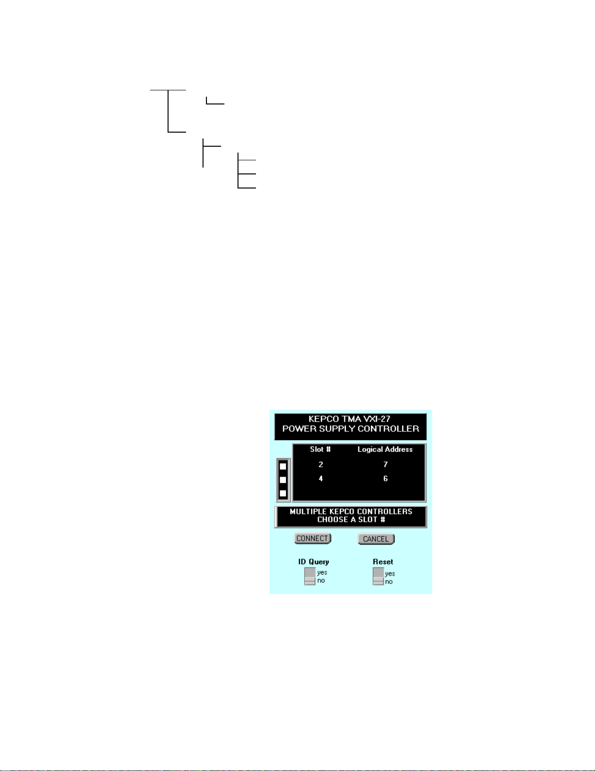
The software will search for TMA VXI-27 controllers installed in the VXI mainframe. The first
screen (shown below, Figure 3-2) lists the TMA VXI-27 Controller(s) installed, showing the
associated slot and assigned logical address. Leave ID QUERY and RESET switches set to
NO.
If only one controller is installed, click on the CONNECT button. If more than one controller is
installed, click on a box at the left to select one controller. (Figure 3-2 shows two TMA VXI-27
controllers installed in slots 2 and 4 corresponding to logical addresses 7 and 6, respectively.)
(KEPCO TMA VXI-27 SUBDIRECTORY)
(standalone soft front panel for TMA VXI-27)
(LabView drivers for TMA VXI-27)
(MS-Windows help file for TMA VXI-27)
plug&play
DIRECTORY STRUCTURE
The ID QUERY and RESET switches should be left in the NO position. (ID QUERY set to ON
will send a verification of the type of instrument installed to the VXI Resource Manager. RESET
set to ON will cause all power supplies to be reset to the initial power on condition when the controller is initialized.)
TMA VXI -27 101602
FIGURE 3-2. TMA VXI-27
plug&play
CONTROLLER SELECTION
3-3
Page 21
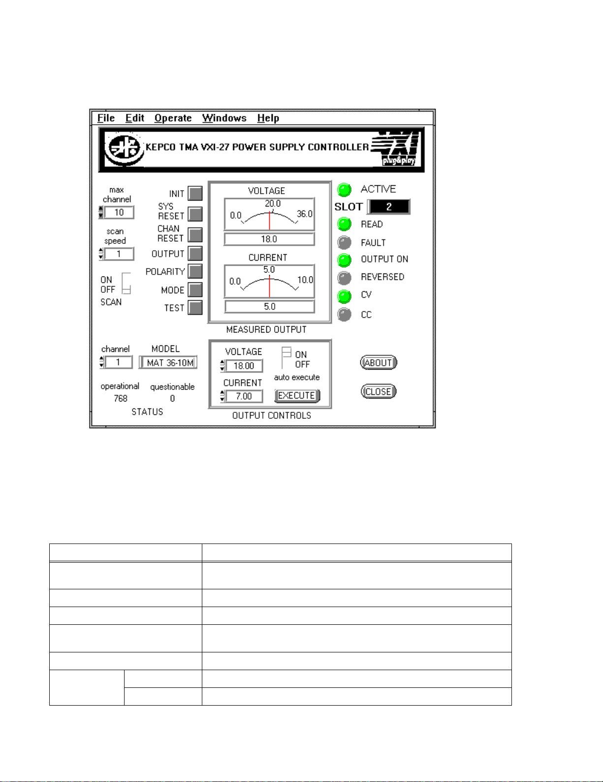
Once a controller has been selected, you will see the "virtual" panel of the Kepco power supply,
(Figure 3-3). The slot selected is displayed in the SLOT window at the upper left corner of the
panel. To operate the controls, click the mouse.
FIGURE 3-3. TMA VXI-27
plag&play
PANEL
3.3.3.1 UNDERSTANDING THE CONTROLS. For on-line information about controls and indicators,
click on SHOW HELP from the HELP menu. Then move the cursor over each control and indicator on the panel. Help text will appear and explain the function of each. Table 3-1 lists the
function of each control and indicator.
TABLE 3-1. Plug&play PANEL CONTROLS AND INDICATORS
CONTROL/INDICATOR FUNCTION
Click on arrows to increase or decrease the number of channels to be scanned; set to
correspond to the number of power supplies actually connected to the controller.
Click on arrows to select channel. Power supply connected to selected channel (indicated by MODEL indicator) is visible on “virtual” panel.
TMA VXI -27 101602
3-4
MAX CHANNEL (switch)
SCAN SPEED(switch) Click on arrows to select scan speed from fastest (10) to slowest (1).
SCAN ON/OFF (switch) Click to enables or disable polling of power supplies connected to the active controller.
CHANNEL (switch)
MODEL (indicator) Indicates power supplly model connected to selected channel.
STATUS
(indicators)
OPERATIONAL Indicates value of status bits in operational register (see Figure B-17)
QUESTIONABLE Indicates value of status bits in questionable register (see Figure B-23)
Page 22

TABLE 3-1. Plug&play PANEL CONTROLS AND INDICATORS (CONTINUED)
CONTROL/INDICATOR FUNCTION
INIT (switch)
SYS RESET (switch)
CHAN RESET (switch)
OUTPUT (switch)
POLARITY (switch)
MODE (switch) Click to select Constant Voltage or Constant Current (alternate action).
TEST (switch)
MEASURED
OUTPUT
(indicators)
OUTPUT
CONTROLS
Click to select a different controller. If only one controller is installed, it will be automatically selected.
Click to reset all power supplies connected to the selected controller (power supplies
are reset to initial power-on condition)
Click to reset only the selected power supply (power supply is reset to initial power-on
condition)
Click to enable or disable the selected power supply output. (Operates relays on
power supply models with relays; otherwise output voltage and current is set to zero.
Click to reverse polarity of power supply models incorporating polarity reversal feature.
Programs all power supplies connected to the controller to their maximum value,
resets them, opens all relays (if present), then checks for errors in output. If error is
detected, the channel number of the failed unit is selected, and the status values indicate the type of error detected.
VOLTAGE meter Provides analog and digital indication of measured voltage.
CURRENT meter
VOLTAGE
CURRENT
EXECUTE
(switch)
Provides analog and digital indication of measured current
Click on arrows to set voltage. If AUTOEXECUTE is set to ON, voltage value is immediately applied to power suply. If AUTOEXECUTE is set to OFF, voltage value is not
applied to selected power supply until EXECUTE is clicked.
Click on arrows to set current. If AUTOEXECUTE is set to ON, current value is immediately applied to power suply. If AUTOEXECUTE is set to OFF, current value is not
applied to selected power supply until EXECUTE is clicked.
With AUTOEXECUTE set to OFF, click to apply VOLTAGE and CURRENT values to
selected power supply.
ACTIVE (indicator) Lights (green) to indicate controller is active.
SLOT (indicator) Displays slot of active controller
READ (indicator) Lights (green) to indicate controller is reading infirmation from power supply.
FAULT (indicator) Lights (red) to indicate error detected. Error indicated by STATUS register values.
OUTPUT ON (indicator) Lights (green) when power supply output is enabled.
REVERSED (indicator) Lights (green) when power supply output polarity is reversed.
CV (indicator)
CC (indicator)
TMA VXI -27 101602
AUTOEXECUTE
ON/OFF
(switch)
Click to set ON/OFF (alternate action). When set to OFF, EXECUTE must be clicked
to apply VOLTAGE and CURRENT values to selected power supply. When set to ON,
VOLTAGE and CURRENT values are immediately applied to the selected power supply.
Lights (green) when power supply is in Constant Voltage mode. (If the Voltage Limit is
exceeded while the power supply was programmed to be in Constant Current mode,
the power supply will be forced into Constant Voltage mode (CV turns green) and the
FAULT indicator lights (red).
Lights (green) when power supply is in Constant Current mode. (If the Current Limit is
exceeded while the power supply was programmed to be in Constant Voltage mode,
the power supply will be forced into Constant Current mode (CC turns green) and the
FAULT indicator lights (red).
3-5
Page 23

TABLE 3-1. Plug&play PANEL CONTROLS AND INDICATORS (CONTINUED)
CONTROL/INDICATOR FUNCTION
ABOUT Click for information about TMA VXI-27 plug&play driver.
CLOSE Click to close plug&play soft panel. Closing the panel does not
3.3.3.2 SELECT THE CHANNEL. Click on the arrows on the CHANNEL box at the lower left. You will see the Kepco power supply Models connected to the system.
3.3.3.3 SET THE VOLTAGE/CURRENT. In the OUTPUT CONTROLS box at the lower center, click on the arrows to increase or decrease the voltage and current. If the power supply is set to Constant Voltage mode (CV indicator green), the CURRENT setting is the Current Limit. Similarly, if the power supply is set to Constant Current mode (CC green), the VOLTAGE setting is the voltage limit.
3.3.3.4 APPLY PROGRAMMED SETTINGS TO THE POWER SUPPLY. Click on EXECUTE. The programmed values for voltage and current limit are now applied to the selected power supply. If AUTOEXECUTE is clicked to ON, the VOLTAGE and CURRENT settings will be immediately applied to the selected power supply.
3.3.3.5 ENABLE THE POWER SUPPLY OUTPUT. Click on the OUTPUT button to the left of the meters to enable the output. The OUTPUT ON indicator turns green. The measured values of voltage and current are indicated by the VOLTAGE and CURRENT meters. Note that the meters give both a digital and analog representation of voltage and current.
3.4 VXIBUS COMMUNICATION
Table 3-2 defines the VXI commands implemented in the TMA VXI-27 in accordance with Specification VXI-1, Rev. 1.4 for a class I4 instrument.
TABLE 3-2. VXI BUS COMMANDS
VXI Command Description
ABORT NORMAL
OPERATION
ASSIGN INTERRUPTER
LINE
ASYNCHRONOUS MODE
CONTROL
BEGIN NORMAL OPERATION (With or without TOP
LEVEL bit)
Causes the TMA VXI-27 to cease normal operation and return to its
default configuration (the same configuration occurring after hardware
reset at power up) with interrupt unasserted.
Used to assign a VXIbus IRQ line to the TMA VXI-27 module interrupter. The default value is 0 which means NO INTERRUPTS.
Used to direct the path of events and responses and also enable or
disable the generation of events and responses. The TMA VXI-27
supports only EVENTS as INTERRUPTS; any other combination will
generate an error
Notifies the TMA VXI-27 that it can begin normal operation. In
response, the TMA VXI-27 sets the corresponding flags in order to be
ready to receive commands through the WORD SERIAL PROTOCOL.
The TOP LEVEL bit (bit 8) is used to identify the device as a Top Level
Commander.
TMA VXI-27
Responds if active
substate is:
Configure
YES NO
YES NO
YES NO
YES NO
Normal
Operation
3-6
TMA VXI -27 101602
Page 24

TABLE 3-2. VXI BUS COMMANDS (CONTINUED)
VXI Command Description
TMA VXI-27
Responds if active
substate is:
Configure
Normal
Operation
BYTE AVAILABLE Sends SCPI or CIIL commands to the TMA VXI-27. Also used to send
BYTE AVAILABLE + END Same as BYTE AVAILABLE except that bit 8 (END) is set to identify
BYTE REQUEST Reads responses from commands previously sent to the TMA VXI-27. NO YES
CLEAR Causes the TMA VXI-27 to clear its internal buffers and reset the VXI
CONTROL EVENT Causes the TMA VXI-27 to selectively enable or disable the genera-
CONTROL RESPONSE Implemented; however, since the TMA VXI-27 does not generate
END NORMAL
OPERATION
IEEE 488.2 common commands.
the byte as the last byte of the message.
error.
tion of a specific event. The TMA VXI-27 can generate two events,
REQUEST TRUE and REQUEST FALSE. After power up, these
events are both enabled (in accordance with the VXI Specification).
The REQUEST TRUE event is sent when the TMA VXI-27 requires
service from its commander (the SERVICE REQUEST bit from the
status byte goes TRUE and the EVENTS AS INTERRUPT and
REQUEST TRUE FLAG are enabled).
The REQUEST FALSE event is sent by the TMA VXI-27 when it no
longer requires service from its commander (the SERVICE REQUEST
bit from the status byte goes FALSE and the EVENTS AS INTERRUPT and REQUEST FALSE FLAG are enabled).
response signals or response interrupts, any attempt to enable
responses will generate an error.
Causes the TMA VXI-27 to end the normal operation and to go back to
the CONFIGURE sub-state. This command will report an error (7 in
the STATUS FIELD) if the device was already in the configure state
when the command was issued.
NO YES
NO YES
YES NO
YES NO
YES NO
YES NO
READ INTERRUPTER
LINE
READ INTERRUPTERS Used to determine the number of interrupters within a SERVANT
READ PROTOCOL Used to determine what protocols, in addition to the Word Serial Pro-
TMA VXI -27 101602
Used to determine the VXIbus IRQ line assigned to the TMA VXI-27
interrupter. The default value is 0 which means NO INTERRUPTS.
device. The TMA VXI-27 has only one interrupter, therefore 1 will be
returned in the answer word. This result will be used in the next command (READ INTERRUPTER LINE) in which the commander can
interrogate the TMA VXI-27 to determine which IRQ line is connected
to this interrupter.
tocol, the TMA VXI-27 supports. This is usually the first command sent
by the Resource Manager after power up and determines all subsequent commands issued to the device. The TMA VXI-27 response to
this command is 8623 Hex which means that it is capable of Event
Generation, that it has a Programmable Interrupter (which means it
supports the Read Interrupters, Read Interrupter Line, and Assign
Interrupter Line commands), that it supports Word Serial TRIGGER
command and that it also supports the VXIbus Instrument Protocol as
an I4 class Instrument.
YES NO
YES NO
YES NO
3-7
Page 25

TABLE 3-2. VXI BUS COMMANDS (CONTINUED)
VXI Command Description
TMA VXI-27
Responds if active
substate is:
Configure
Normal
Operation
READ PROTOCOL
ERROR
READ STB Used to read the status word from the TMA VXI-27. Because the TMA
NOTE: It is more advantageous to execute the VXIbus Word Serial Protocol READ STB command than the *STB? because it is
faster (only one VXI cycle) and more accurate than *STB? It is more accurate because STB? is a query (which asks for
Word Serial Read; BYTE REQUEST command is the reply) which will always have the Message Available bit reset
(because taking the reply empties the output queue). Instead, the VXI READ STB shows the exact status of the output
queue (it does not use the output queue for the reply).
Issued by the COMMANDER to interrogate the TMA VXI-27 about the
cause of its current error (the TMA VXI-27 has activated the Err bit in
the Response register). The errors which can be reported by the TMA
VXI-27 are the following: Multiple Queries, Unsupported Command,
DIR Violation, DOR Violation, Write Ready Violation.
VXI-27 is a class I4 Instrument (implementing the IEEE 488.2 common commands), the value returned is the same as the value read by
executing *STB?.
YES NO
NO YES
3.4.1 TYPICAL VXIBUS START-UP SEQUENCE
The following is a typical sequence of commands which are sent to the TMA VXI-27 by the
resource manager upon power up:
1. The first command is READ PROTOCOL; the TMA VXI-27 replies with 8623 Hex (as
described in Table 3-2 above).
2. the next command is READ INTERRUPTERS to determine the IRQ line assigned to the
TMA VXI-27 interrupter.
3. This is followed by ASSIGN INTERRUPTER LINE which connects the TMA VXI-27 inter-
rupter to an active IRQ line (between 1 and 7) if the resource manager wants events sent as
interrupts. This can be followed by READ INTERRUPTER LINE if the resource manager
wants to verify that the interrupter is connected to the requested IRQ line.
4. After configuration commands described above, it is expected that the resource manager will
issue the BEGIN NORMAL OPERATION COMMAND followed by *idn? (SCPI command) to
identify the TMA VXI-27.
5. The power modules connected to the TMA VXI-27 can now be programmed using either
SCPI (PAR. 3.5) or CILL (PAR. 3.6) commands sent as Word Serial Protocol Messages.
3.5 SCPI PROGRAMMING
SCPI (Standard Commands for Programmable Instruments) is a programming language conforming to the protocols and standards established by IEEE 488.2 (reference document ANSI/
IEEE Std 488.2, IEEE Standard Codes, Formats, Protocols, and Common Commands). SCPI commands are sent to the TMA VXI-27 controller as output strings within the selected programming
language (PASCAL, BASIC, etc.) in accordance with the VXIbus command protocol (PAR. 3.4).
3.5.1 SCPI MESSAGES
There are two kinds of SCPI messages: program messages from controller to power supply,
and response messages from the power supply to the controller. Program messages consist of
one or more properly formatted commands/queries and instruct the power supply to perform an
3-8
TMA VXI -27 101602
Page 26

action; the controller may send a program message at any time. Response messages consist of
formatted data; the data can contain information regarding operating parameters, power supply
state, status, or error conditions.
3.5.2 COMMON COMMANDS/QUERIES
Common commands and queries are defined by the IEEE 488.2 standard to perform overall
power supply functions (such as identification, status, or synchronization) unrelated to specific
power supply operation (such as setting voltage/current). Common commands and queries are
preceded by an asterisk (*) and are defined and explained in APPENDIX A (see Table 3-3).
Refer also to syntax considerations (PAR.s 3.5.3 through 3.5.8).
3.5.3 SCPI SUBSYSTEM COMMAND/QUERY STRUCTURE
Subsystem commands/queries are related to specific power supply functions (such as setting
output voltage, current limit, etc.) Figure 3-4 is a tree diagram illustrating the structure of SCPI
subsystem commands used in the TMA VXI-27 with the “root” at the left side, and specific commands forming the branches. The subsystem commands are defined and explained in Appendix
B (see Table 3-3).
ROOT : (colon)
INITiate
[:IMMediate]
:CONTinuous
INSTrument
:CATalog
:NSELect
:SELect
:STATe
MEASure
:CURRent?
:VOLTage?
OUTPut
[:STATe]
[SOURce:]
VOLTage
[:LEVel]
[:IMMediate]
:TRIGgered
CURRent
[:LEVel]
[:IMMediate]
:TRIGgered
FUNCtion
:MODE
STATus
:OPERation
:CONDition?
:ENABle
[:EVENt]?
:PRESet
:QUEStionable
:CONDition?
:ENABle
[:EVENt]?
:INSTrument?
:ENB
:ISUM
:INSTrument1?
:ENB
:INSTrument2?
:ENB
SYSTem
:COMMunication
:GPIB:ADDRess
:SERial
:BAUD
:ECHO
:PACE
:PROM
:ERRor?
:CODE?
:ALL?
:LANGuage
:SET
:VERSion?
FIGURE 3-4. TREE DIAGRAM OF SCPI COMMANDS USED WITH TMA VXI-27 CONTROLLER
TMA VXI -27 101602
3-9
Page 27

TABLE 3-3. SCPI COMMAND INDEX
COMMAND
*CLS B.2 INST:STAT C.9 STAT:QUES? C.28
*ESE B.3 MEAS:CURR? C.10 STAT:QUES:COND? C.29
*ESE? B.4 MEAS:VOLT? C.11 STAT:QUES:ENAB C.30
*ESR? B.5 OUTP:[STAT] C.12 STAT:QUES:ENAB? C.31
*IDN? B.6 OUTP:[STAT}? C.13 STAT:QUES:INST? C.32
*OPC, *OPC? B.7, B.8 [SOUR]:CURR C.14 STAT:QUES:INST1? C.33
OPT? B.9 [SOUR]:CURR? C.15 STAT:QUES:INST2? C.34
*RST B.10 [SOUR]:CURR:TRIG C.16 STAT:QUES:INST:ENAB, ? C.35, C.36
*SRE B.11 [SOUR]:CURR:TRIG? C.17 STAT:QUES:INST1:ENAB, ? C.37, C.38
*SRE? B.12 [SOUR]:VOLT C.18 STAT:QUES:INST2:ENAB, ? C.39, C.40
*STB? B.13 [SOUR]:VOLT? C.19 STAT:QUES:INST:ISUM? C.41
*TRG B.14 [SOUR]:VOLT:TRIG C.20 STAT:QUES:INST:ISUM:ENAB, ? C.42, C.43
*TST B.15 [SOUR]:VOLT:TRIG? C.21 SYST:ERR C.44
*WAI B.16 [SOUR]:FUNC:MODE C.22 SYST:ERR:CODE? C.45
INIT[:IMM] C.2 STAT:OPER:COND? C.23 SYST:ERR:CODE:ALL? C.46
PAR.
REFERENCE
COMMAND
PAR.
REFERENCE
COMMAND
PAR.
REFERENCE
INIT:CONT C.3 STAT:OPER:ENAB C.24 SYST:LANG C.47
INIT:CONT? C.4 STAT:OPER:ENAB? C.25 SYST:SET C.48
INST:CAT C.5 STAT:OPER? C.26 SYST:VERS? C.49
INST, INST? C.6, C.7, C.8 STAT:PRES C.27
3.5.4 PROGRAM MESSAGE STRUCTURE
SCPI program messages (commands from controller to power supply) consist of one or more
message units ending in a message terminator. The message terminator is not part of the syntax; it
is defined by the way your programming language indicates the end of a line (such as a “newline” or “end-of-line” character). The message unit is a keyword consisting of a single command
or query word followed by a message terminator (e.g., CURR?<newline> or TRIG<end-ofline>). The message unit may include a data parameter after the keyword separated by a space;
the parameter is usually numeric (e.g., CURR 5<newline>), but may also be a string (e.g.,
OUTP ON<newline>). Figure 3-5 illustrates the message structure, showing how message units
are combined. The following subparagraphs explain each component of the message structure.
NOTE: An alternative to using the message structure for multiple messages defined in the fol-
lowing paragraphs is to send each command as a separate line. In this case each command must use the full syntax shown in Appendix B.
3-10
TMA VXI -27 101602
Page 28

KEYWORD
ROOT SPECIFIER
MESSAGE UNIT SEPARATOR
DATA SEPARATOR
DATA
DATA SEPARATOR
KEYWORD
KEYWORD SEPARATOR
KEYWORD
3.5.4.1 KEYWORD
Keywords are instructions recognized by a decoder within the TMA VXI-27, referred to as a
“parser.” Each keyword describes a command function; all keywords used by the TMA VXI-27
are listed in Figure 3-4.
DATA
CURR:LEV 3.5;:OUTP ON;:CURR?<NL>
FIGURE 3-5. MESSAGE STRUCTURE
MESSAGE UNIT SEPARATOR
ROOT SPECIFIER
KEYWORD
QUERY INDICATOR
MESSAGE TERMINATOR
MESSAGE UNIT
Each keyword has a long form and a short form. For the long form the word is spelled out completely (e.g., STATUS, OUTPUT, VOLTAGE, and TRIGGER are long form keywords). For the
short form only the first three or four letters of the long form are used (e.g., STAT, VOLT, OUTP,
and TRIG). The rules governing short form keywords are presented in Table 3-4.
IF NUMBER OF LETTERS IN
LONGFORM KEYWORD IS:
4 OR FEWER (DOES NOT MATTER) ALL LONG FORM LETTERS MODE
5 OR MORE NO
5 OR MORE YES
TMA VXI -27 101602
TABLE 3-4. RULES GOVERNING SHORTFORM KEYWORDS
AND FOURTH LETTER
IS A VOWEL?
THEN SHORT FORM
CONSISTS OF:
THE FIRST FOUR
LONG FORM LETTERS
THE FIRST THREE
LONG FORM LETTERS
MEASure, OUTPut, EVENt
LEVel, IMMediate, ERRor
EXAMPLES
3-11
Page 29

You must use the rules above when using keywords. Using an arbitrary short form such as
ENABL for ENAB (ENABLE) or IMME for IMM (IMMEDIATE) will result in an error. Regardless
of which form chosen, you must include all the letters required by that form.
To identify the short form and long form in this manual, keywords are written in upper case letters to represent the short form, followed by lower case letters indicating the long form (e.g.,
IMMediate, EVENt, and OUTPut). The parser, however, is not sensitive to case (e.g., outp,
OutP, OUTPUt, ouTPut, or OUTp are all valid).
3.5.4.2 KEYWORD SEPARATOR
If a command has two or more keywords, adjacent keywords must be separated by a colon (:)
which acts as the keyword separator (e.g., CURR:LEV:TRIG). The colon can also act as a root
specifier (PAR. 3.5.4.7).
3.5.4.3 QUERY INDICATOR
The question mark (?) following a keyword is a query indicator. This changes the command into
a query. If there is more than one keyword in the command, the query indicator follows the last
keyword. (e.g., VOLT? and MEAS:CURR?).
3.5.4.4 DATA
Some commands require data to accompany the keyword either in the form of a numeric value
or character string. Data always follows the last keyword of a command or query (e.g.,
VOLT:LEV:TRIG 14 or SOUR:VOLT? MAX
3.5.4.5 DATA SEPARATOR
Data must be separated from the last keyword by a space (e.g., VOLT:LEV:TRIG 14 or
SOUR:VOLT? MAX
3.5.4.6 MESSAGE UNIT SEPARATOR
When two or more message units are combined in a program message, they must be separated
by a semicolon (;) (e.g., VOLT 15;MEAS:VOLT? and CURR 12; CURR:TRIG 12.5).
3.5.4.7 ROOT SPECIFIER
The root specifier is a colon (:) that precedes the first keyword of a program message. This
places the parser at the root (top left, Figure 3-4) of the command tree. Note the difference
between using the colon as a keyword separator and a root specifier in the following examples:
VOLT:LEV:IMM 16 Both colons are keyword separators.
:CURR:LEV:IMM 4 The first colon is the root specifier, the other two are keyword separators.
VOLT:LEV 6;:CURR:LEV 15 The second colon is the root specifier, the first and third are keyword separators
:INIT ON;:TRIG;:MEAS:CURR?;VOLT? The first three colons are root specifiers.
3-12
TMA VXI -27 101602
Page 30

3.5.4.8 MESSAGE TERMINATOR
The message terminator defines the end of a message. Three message terminators are permitted:
• new line (<NL>), ASCII 10 (decimal) or 0A (hex)
• (<CR>), ASCII 13 (decimal) or 0D (hex)
• both of the above (<CR> <NL>)
Your GPIB interface card software will automatically send a message terminator. For example,
the HP BASIC OUTPUT statement inserts <NL> after the last data byte. When binary data is
exchanged, <END> must be used. The combination <NL><END> terminator can be used for all
data except binary data.
NOTE: Kepco power modules require a message terminator at the end of each program mes-
sage. The examples shown in this manual assume a message terminator will be added
at the end of each message. Where a message terminator is shown it is represented
as <NL> regardless of the actual terminator character.
3.5.5 UNDERSTANDING THE COMMAND STRUCTURE
Understanding the command structure requires an understanding of the subsystem command
tree illustrated in Figure 3-4. The “root” is located at the top left corner of the diagram. The
parser goes to the root if:
• a message terminator is recognized by the parser
• a root specifier is recognized by the parser
Optional keywords are enclosed in brackets [ ] for identification; optional keywords can be omitted and the power supply will respond as if they were included in the message. The root level
keyword [SOURce] is an optional keyword. Starting at the root, there are various branches or
paths corresponding to the subsystems. The root keywords for the TMA VXI-27 are :INITiate,
:MEASure, :OUTPut, [:SOURce], :STATus, and :SYSTem. Because the [SOURce] keyword is
optional, the parser moves the path to the next level, so that VOLTage, CURRent, and FUNCtion commands are at the root level.
Each time the parser encounters a keyword separator, the parser moves to the next indented
level of the tree diagram. As an example, the STATus branch is a root level branch that has
three sub-branches: OPERation, PRESet, and QUEStionable. The following illustrates how
SCPI code is interpreted by the parser:
STAT:PRES<NL>
The parser returns to the root due to the message terminator.
STAT:OPER?;PRES<NL>
The parser moves one level in from STAT. The next command is expected at the level defined
by the colon in front of OPER?. Thus you can combine the following message units
STAT:OPER? and STAT:PRES;
STAT:OPER:COND?;ENAB 16<NL>
After the OPER:COND? message unit, the parser moves in one level from OPER, allowing the
abbreviated notation for STAT:OPER:ENAB.
TMA VXI -27 101602
3-13
Page 31

3.5.6 ADDRESSING MULTIPLE POWER SUPPLIES
Power supplies on the IEEE 1118 bus are selected by node address, also referred to as node
number or channel number. Refer to the applicable manuals for the power modules connected
to the IEEE 1118 bus to set each power module to a unique node number, from 1 to 31 (a maximum of 27 power modules may be connected to the bus).
The node number may follow any part of a SCPI command. Note that there must be no space
preceding the node number
e.g., meas2:volt? or meas:volt2? both measure output voltage of the power supply at node
number 2.
e.g., func3:mode volt or func:mode3 volt both set the power supply at node number 3 to
commanded voltage mode.
e.g., stat1:ques? or stat:ques1? or stat:ques:cond1? all read Questionable Register
status of the power supply at node number 1.
Upon power turn-on, commands sent without a node (channel) number will go to the default
node address (1) until another node number is specified. Once another node number is specified, the new number becomes the default until another is specified.
NOTE: The node selected can also be changed using the INSTrument:SELect <N> command.
This allows subsequent commands to operate on the specified node (e.g. INST:SEL 10
causes node 10 to be selected).
3.5.7 UNDERSTANDING THE COMMAND STRUCTURE
Understanding the command structure requires an understanding of the subsystem command
tree illustrated in Figure 3-4. The “root” is located at the top left corner of the diagram. The
parser goes to the root if:
• a message terminator is recognized by the parser
• a root specifier is recognized by the parser
Optional keywords are enclosed in brackets [ ] for identification; optional keywords can be omitted and the power supply will respond as if they were included in the message. The root level
keyword [SOURce] is an optional keyword. Starting at the root, there are various branches or
paths corresponding to the subsystems. The root keywords for the TMA VXI-27 controller are
:INITiate, :MEASure, :OUTPut, [:SOURce], :STATus, and :SYSTem. Because the [SOURce]
keyword is optional, the parser moves the path to the next level, so that VOLTage, CURRent,
and FUNCtion commands are at the root level.
Each time the parser encounters a keyword separator, the parser moves to the next indented
level of the tree diagram. As an example, the STATus branch is a root level branch that has
three sub-branches: OPERation, PRESet, and QUEStionable. The following illustrates how
SCPI code is interpreted by the parser:
STAT:PRES<NL>
The parser returns to the root due to the message terminator.
3-14
STAT:OPER?;PRES<NL>
The parser moves one level in from STAT. The next command is expected at the level defined
TMA VXI -27 101602
Page 32

by the colon in front of OPER?. Thus you can combine the following message units
STAT:OPER? and STAT:PRES;
STAT:OPER:COND?;ENAB 16<NL>
After the OPER:COND? message unit, the parser moves in one level from OPER, allowing the
abbreviated notation for STAT:OPER:ENAB.
3.5.8 PROGRAM MESSAGE SYNTAX SUMMARY
• Common commands begin with an asterisk (*).
• Queries end with a question mark (?).
• Program messages consist of a root keyword and, in some cases, one or more message
units separated by a colon (:) followed by a message terminator. Several message units
of a program message may be separated by a semicolon (;) without repeating the root
keyword.
• If a program message has more than one message unit, then a colon (:) must precede
the next keyword in order to set the parser back to the root (otherwise the next keyword
will be taken as a subunit of the previous message unit).
e.g., the command meas:volt?;curr? will read output voltage and output current
since both volt? and curr? are interpreted as subunits of the meas command.
• Several commands may be sent as one message; a line feed terminates the message.
Commands sent together are separated by a semicolon (;). The first command in a message starts at the root, therefor a colon (:) at the beginning is not mandatory.
e.g., the command meas:volt?;:curr? will read output voltage and programmed current since the colon preceding curr? indicates that curr? is not part of the meas command and starts at the root.
• UPPER case letters in mnemonics are mandatory (short form). Lower case letters may
either be omitted, or must be specified completely (long form)
e.g., INSTrument (long form) has the same effect as INST (short form).
• Commands/queries may be given in upper/lower case (long form)
e.g., SoUrCe is allowed.
• Text shown between brackets [] is optional.
e.g., :[SOUR]VOLT:[LEV] TRIG has the same effect as :VOLT TRIG
3.5.9 STATUS REPORTING
The status reporting of the TMA VXI-27 follows the SCPI and IEEE 488.2 requirements. The
serial poll response of the TMA VXI-27 provides summary bits of the status and error reporting
system. The simplest status report is the command valid reporting and data availablity, This
successful decoding of a command string generates no error and is indicated by the bit 3 of the
serial poll response being a zero. The setting of bit 4 in the status byte indicates data is available to the controller in response a command query message.
TMA VXI -27 101602
3-15
Page 33

3.5.9.1 STATUS REPORTING STRUCTURE
The status reporting of the TMA VXI-27 uses four status registers, illustrated in Figure 3-6.
These registers are the Questionable, Operation, Standard Event and Service Request registers. The Questionable and Operation registers are 16 bit registers and the Standard Event and
Service Request registers are 8 bits. These four registers are referred to as condition registers.
Each of the four condition registers is associated with two related registers: an event register
which holds unlatched events reported in realtime by the instrument and is cleared by reading
the register, and an enable register which allows the contents of the event register to be passed
through to set the associated condition register.
A zero to one transition of a condition register is added to the event register if the specific bit in
the enable register is also a 1. Reading an event register clears all of the bits found in the event
register. If any bits are set in an event register, the following condition register bit is then set.
For example, if the STAT:QUES:ENB (enable) register has bit 0 set and a voltage error is
detected, the event registers bit 0 is set. The 1 in the event register causes bit 3 of the status
byte to be asserted. The Service Request register is ANDed with its enable register for all bits
except bit 6. The result is placed in bit 6 of the Service Request register. If bit 6 is a 1 (true), it
causes the TMA VXI-27 to assert the SRQ line to the host controller.
Figure 3-6 also shows that if the error/event queue is not empty, bit 3 is set in the Service
Request register and bit 4 indicates that a message is available in the output buffer.
3.5.9.2 OPERATIONAL STATUS REGISTER
The OPERational condition register contains conditions which are a part of the instrument’s normal operation. The definition of each of these bits (condition register) is as follows:
• 1 through 7 - Not Used — always zero.
• 8 - Constant Voltage — 1 indicates the instrument is in constant voltage mode.
• 9 - Relay — 1 indicates the power supply output relay is closed.
• 10 - Constant Current — 1 indicates the instrument is in constant current mode.
• 11 through15 - Not Used — always zero.
3.5.9.3 QUESTIONABLE STATUS REGISTER
The QUEStionable condition register (see Figure 3-6) contains status bits representing data/signals which give an indication of the quality of various aspects of the signal.
A bit set in the QUEStionable condition register indicates that the data currently being acquired
or generated is of questionable quality due to some condition affecting the parameter associated with that bit.
• 8 - Voltage Mode — 1 indicates the instrument is in Voltage mode.
• 9 - Relay — 1 indicates the power supply output relay is closed, unit is supplying power
at output terminals.
3-16
• 10 - Current Mode — 1 indicates the Power Supply is in Current mode. Changes in this
bit do not affect the event register.
• 14 - Command warning — This bit indicates a non-fatal warning that relates to the
instrument’s interpretation of a command, query, or on or more parameters of a specific
TMA VXI -27 101602
Page 34

command or query. The power supply sets this bit for
– MEAS:VOLT? 10,1 — The 10 is the number of digits and the 1 is the range. Since
this capability is not implemented in Kepco power supplies, the Command Warning
bit is set.
– INST:SEL 2 sent to a single power supply. Trying to select unit 2 when only one
power supply is connected causes the Command Warning bit to be set.
TMA VXI -27 101602
FIGURE 3-6. STATUS REPORTING STRUCTURE
3-17
Page 35

3.5.9.4 MULTIPLE LOGICAL INSTRUMENTS
The TMA VXI-27 is a SCPI device that supports multiple logical instruments; it allows a choice
between two methods of status reporting. The status reporting default upon powerup treats the
unit as a single channel instrument. When multiple channels are in use, a SCPI compliant status
structure can be selected which provides an INSTrument summary status register and an individual instrument ISUMmary for each logical instrument. These registers are equivalent to the
Status Questionable register of a single channel instrument and are also found in the STATus
Questionable register for the selected channel. The contents of the STATus Questionable register can also contain the summary of all instruments as shown in Figure 3-7.
The selection of the status reporting structure is controlled by the SYStem:SET SI (Instrument
Structure) command, either SI0 (off) or SI1 (on). The power-up default is the off condition. To
enable the SCPI compliant mode of operation for multiple logical instruments the user must
send SYSTem:SET SI1 to the TMA VXI-27 power supply during initialization. The SI1 state is
not remembered when the unit is turned off. To return to the standard method of reporting the
selected device’s status without turning the unit off, send SYSTem:SET SI0.
When the TMA VXI-27 power supply is set up for SCPI compliant status reporting for multiple
channels, the specific instrument’s Questionable register is found in the
STAT:QUES:INST:ISUM<n> register. This register has the same bit structure as the single
channel Questionable register. The ISUM enable register is ANDed with the bits of the channel’s ISUM register and its bit is placed in the INST register. The Questionable register bits are
the logical ORing of all channels’ Questionable ISUM register. This is shown in figure 3-7.
The ISUMmary registers set the INSTrument register, which in turn sets bit 13 of the QUEStionable or OPERation status register. This is shown pictorially in Figure 3-7.
The STATUS:QUESTIONABLE and STATUS:QUESTIONABLE:CONDITION registers are the
same in this mode of status reporting. The condition register indicates the status of the various
event registers and bits set are only cleared if the source of the bit is cleared.
3-18
TMA VXI -27 101602
Page 36

FIGURE 3-7. EXPANSION OF QUESTIONABLE REGISTER FOR MULTIPLE LOGICAL INSTRUMENTS
3.5.10 PROGRAM EXAMPLE
Appendix F is a sample program illustrating communication with the TMA VXI-27. The sample
program is written in C language for a National Instruments embedded slot 0 controller using
LabWindows. Although the program is for a specific manufacturer’s hardware, the techniques
for other manufacturers are similar.
The program illustrates:
• how to communicate to the register level
• how to use the Word Serial Protocol
• how to use the interrupt capabilities of the TMA VXI-27, even though they are not used in
the LABVIEW library.
3.6 CIIL PROGRAMMING
The CIIL command language is used on early models of Kepco power supplies and controllers.
The command functions are included here for compatibility with other equipment programmed
with CIIL commands. The CIIL command set for the TMA VXI-27 Controller is defined and
explained in Appendix D.
3.7 CALIBRATION
The TMA 4882-27 requires no calibration.
3.8 MAINTENANCE
No preventive or scheduled maintenance is requuired.
TMA VXI -27 101602
3-19/(3-20 Blank)
Page 37

Page 38

APPENDIX A - MS WINDOWS HELP FILES
A.1 SOFT FRONT PANEL
A.1.1 SOFT FRONT PANEL OVERVIEW
The soft front panel may be executed by clicking on the icon in the VXIPNP group or by running
‘kptmavxi.exe’. It provides a means of checking out your Kepco power supply system as soon
as you plug in the TMA VXI-27 controller and connect your Kepco power supplies to it.
A.1.2 SOFT FRONT PANEL CONTROLS
A.1.2.1 Init
The Init control allows selection of a Kepco TMA VXI-27 power supply controller, if more than 1
controller is present. If only one is present it will automatically be selected. If no controllers are
present a message will appear and the function should be canceled.
A.1.2.2 Channel
The Channel control is used to select the power supply to which subsequent commands shall
be applied.
A.1.2.3 Voltage
The Voltage control is used to set the value of output voltage to which the power supply shall be
programmed. If AutoExecute is set to the ON position, the command is issued immediately, otherwise the execute button must be pressed to apply the new value.
A.1.2.4 Current
The Current control is used to set the value of output current to which the power supply shall be
programmed. If AutoExecute is set to the ON position, the command is issued immediately, otherwise the execute button must be pressed to apply the new value.
A.1.2.5 Mode
The Mode control selects which mode of operation, constant voltage or constant current, the
power supply should operate in. If the selected mode is not possible, because of the load value,
an overload status error will be set in the questionable status register.
A.1.2.6 Output
The Output control is used to enable or disable the output of the power supply, via the output
relay, on models which have relays.
A.1.2.7 Polarity
The Polarity control is used to select the output polarity, positive or negative, of the power supply, on units which have output relays.
TMA VXI-27 101602
A-1
Page 39

A.1.2.8 Sys Reset
The Sys Reset control causes all power supplies connected to the TMA VXI-27 controller to
reset to their power on state.
A.1.2.9 Chan Reset
The Chan Reset control causes the selected channel to reset to its power on state.
A.1.2.10 Test
The Test control programs all power supplies to their maximum output values, then resets them,
opens all relays, if present, and checks for errors in output. If any errors are present the channel
numbers of the failed units are returned, otherwise a 0 is returned.
A.2 LABVIEW LIBRARY
A.2.1 LABVIEW LIBRARY OVERVIEW
The LabView Library provides functions to be used under National Instruments LabView 5.0
control software package for windows. The functions provide a means of controlling Kepco
power supplies.
Most functions contain the following parameters in addition to any function specific parameters:
• Instrument handle In
• Instrument handle out
• Error in
• Error out
A.2.1.1 Instr handle in
This is a unique instrument identifier, which is required by most functions. Its value is obtained
from the AutoCon or Initialize function, at the Instr handle out
A.2.1.2 Instr handle out
This is a unique instrument identifier returned by the initialize or AutoCon function, and is used
by other functions as the Instr handle in
A.2.1.3 Error in
This is the input error cluster, which passes error information to a function. It is usually wired to
the error out
terminal of a preceding function.
A.2.1.4 Error out
This is the output error cluster, which passes error information after a function call. It can be
used to pass the information from a function to the error in
terminal
terminal of the next function called.
A-2
TMA VXI-27 101602
Page 40

A.2.2 LABVIEW LIBRARY FUNCTIONS
A.2.2.1 About
The About function returns information about the software and firmware, including the revision
number of each.
A.2.2.2 AutoCon
The AutoCon function searches the VXI chassis for Kepco controllers and displays a list of controllers found. If more than one is found, the user may select which one to connect to. Upon execution the Kepco controller will be initialized. See also Initialize
A.2.2.3 Chanl
.
The Chanl function allows the selection of a power supply channel. All subsequent functions will
be applied to that channel if no other is specified in the function itself.
A.2.2.4 Close
The Close function terminates a programming session by closing the communication between
the VXI slot 0 controller and the Kepco TMA VXI-27 power supply controller. It must be the last
command issued. Failure to close the instrument may result in eventual out of memory errors.
A.2.2.5 GetStatus
The GetStatus function reads information from various status registers and returns the result in
STATUS as follows:
Status Register values: 0 = Operation register
TMA VXI-27 101602
1 = Questionable register
A-3
Page 41

A.2.2.6 Initialize
The Initialize function may be used when AutoCon is not needed. It is a low level function which
requires an Instrument Descriptor, which includes the logical address of the Kepco controller. It
is recommended that AutoCon
A.2.2.7 Mode
The Mode function selects whether the power supply should operate in Constant Voltage or
Constant Current mode. If the desired mode is not possible, because of the load, an overload
condition will be set in the Questionable Status register.
Status Type values: 0 = Event
1 = Condition
2 = Mask
be used instead.
mode values: 0 = voltage, 1 = current
A.2.2.8 Outp
The Outp function closes or opens the output relay, on units which have relays. On units without
relays, the output is Set to the last programmed value or Reset to 0.
output values: 0 = off, 1 = on
A.2.2.9 Read
The Read function returns the output voltage and current of the power supply.
A-4
TMA VXI-27 101602
Page 42

A.2.2.10 Reset
The Reset function sets the power supply to its power on state. Voltage and current are set to 0,
and relays are opened. If the channel # is set to 0, all power supplies are reset, otherwise, only
the selected channel is reset.
A.2.2.11 RevisionQuery
The RevisionQuery function returns the firmware revision of the Kepco TMA VXI-27 power supply controller and the revision of the Kepco Instrument driver.
See also Vers
A.2.2.12 SelfTest
The SelfTest function opens all output relays, and programs all power supplies to their maximum
levels, then resets the outputs to 0. If any errors in output occurred, the channel number of the
failed supplies are returned, otherwise a 0 is returned. If failures occur, the Questionable Event
register must be read from each failed channel, using the GetStatus
cause of failure and to clear the SelfTest error. This does not apply to the currently selected
channel, since the register value for that channel is automatically returned by the self test function itself.
A.2.2.13 Set
The Set function sets the output voltage and current values of the power supply, as determined
by the load. The load determines if the supply will be in Constant Voltage or Constant Current
mode. See also mode.
.
function, to determine the
TMA VXI-27 101602
A-5
Page 43

A.2.2.14 Vers
The Vers function returns the revision number of the power supply firmware, if a channel number is specified. If the channel is 0, the revision number of the Kepco TMA VXI-27 power supply
controller is returned. For power supplies, the model of the supply is also returned.
A.3 KNOWLEDGE BASE
The Knowledge Base file presents information regarding specific aspects of the Kepco TMA
VXI-27, such as the instrument class, size and weight, the power consumption and the cooling
requirements. It also includes graphic information, stored in a .BMP file, regarding the settings
for the VXI logical address.
A-6
TMA VXI-27 101602
Page 44

APPENDIX B - SCPI COMMON COMMAND/QUERY DEFINITIONS
B.1 INTRODUCTION
This appendix defines the IEEE 488.2 common commands and queries used with the MBT
Power Supply controller. Common commands and queries are preceded by an asterisk (*) and
are defined and explained in Figures A-1 through A-14, arranged in alphabetical order. Table A1 provides a quick reference of all IEEE 488.2 common commands and queries used in the
MBT power supply controller.
TABLE B-1. IEEE 488.2 COMMAND/QUERY INDEX
COMMAND PAR. COMMAND PAR.
*CLS B.2 *RST B.10
*ESE, ? B.3, B.4 *SRE, ? B.11, B.12
*ESR? B.5 *STB? B.13
*IDN? B.6 *TRG B.14
*OPC, ? B.7, B.8 *TST? B.15
*OPT B.9 *WAI B.16
B.2 *CLS — CLEAR STATUS COMMAND
*CLS
Syntax: *CLS
Description: Clears status data. Clears the error queue of the instrument. It also clears the following registers
without affecting the corresponding Enable Registers: Standard Event Status Register (ESR), Operation Status Event Register, Questionable Status Event Register, and Status Byte Register (STB).
Related commands: *OPC *OPC?. (See example, Figure B-1.)
B.3 *ESE — STANDARD EVENT STATUS ENABLE COMMAND *ESE
Syntax: *ESE <integer> where <integer> = positive whole number: 0 to 255 per Table B-2.
Default Value: 0
Description: This command programs the standard Event Status Enable register bits. The contents function
as a mask to determine which events of the Event Status Register (ESR) are allowed to set the ESB
(Event Summary Bit) of the Status Byte Register. Enables the Standard events to be summarized in
the Status Byte register (1 = set = enable function, 0 = reset = disable function). All of the enabled
events of the standard Event Status Enable register are logically ORed to cause ESB (bit 5) of the Sta-
.
tus Byte Register to be set (1 = set = enable, 0 = reset = disable)
(See example, Figure B-1.)
TABLE B-2. STANDARD EVENT STATUS ENABLE REGISTER AND
STANDARD EVENT STATUS REGISTER BITS
CONDITION PON NU CME EXE DDE QUE NU OPC
BIT 76543210
VALUE 128 64 32 16 8 4 2 1
PON Power On
NU (Not Used)
CME Command Error
EXE Execution Error
DDE Device Dependent Error
QUE Query Error
OPC Operation Complete
B.4 *ESE? — STANDARD EVENT STATUS ENABLE QUERY *ESE?
Syntax: *ESE? Return value: Integer> value per Table B-2.
TMA VXI-27 101602
B-1
Page 45

Description: Returns the mask stored in the Standard Event Status Enable Register. Contents of Standard
Event Status Enable register (*ESE) determine which bits of Standard Event Status register (*ESR)
are enabled, allowing them to be summarized in the Status Byte register (*STB). All of the enabled
events of the Standard Event Status Enable Register are logically ORed to cause ESB (bit 5) of the
Status Byte Register to be set (1 = set = enable function, 0 = reset = disable function). (See example,
Figure B-1.)
B.5 *ESR? — EVENT STATUS REGISTER QUERY *ESR?
Syntax: *ESR?
Return value: <integer> (Value = contents of Event Status register as defined in Table B-2.)
Description: Causes the power supply to return the contents of the Standard Event Status register. After it
has been read, the register is cleared. The Standard Event Status register bit configuration is
defined in Table B-2(1 = set, 0 = reset). Related Commands: *CLS, *ESE, *OPC. (See example, Figure B-1.)
B.6 *IDN? — IDENTIFICATION QUERY
Syntax: *IDN?
Return value: Character string
Description: Identifies the instrument. This query requests identification. The string contains the manufacturer
name, model, SN, firmware revs. The SN field is normally used for the serial #, but since serial #s are
not stored in memory , the channel # is given instead. The firmware revision consists of the controller
rev. and power module rev. seperated by a ‘-'. If no module is present at the selected channel, PSC
(Power Supply Controller) is given as the model. Supported models include MAT, MBT, and MST The
character string contains the following fields: <Manufacturer>, <Model>, <Serial Number>, <Firmware
revision> where: <Manufacturer> = KEPCO, <Model> = BOP, <Serial Number> = MM,DD,YY-SSS
(MM - month, DD - day, YY - year, SSS - serial number in that day) <Firmware revision>=n.m (n.m
revision, e.g, 1.0) (See example, Figure B-1.)
The model identified in the *IDN? query after power up of the controller is the device connected to the
BITBUS with an address of 1. If no device is set to be address 1 then the power up IDN string
returned will contain the model identifier of PSC. The model identifier reflects the type of power supply
at a specific BITBUS address. figure C-3 shows an example of the model identifier after specifying any
device.
*IDN?
B.7 *OPC — OPERATION COMPLETE COMMAND *OPC
:
Syntax
Description:
*OPC
Causes power supply to set status bit 0 (Operation Complete) when pending operations are
complete This command sets Standard Event Status Register bit 0 (see Table B-2) to “1” when all
previous commands have been executed and changes in output level have been completed. This
command does not prevent processing of subsequent commands, but bit 0 will not be set until all
pending operations are completed. (1 = set = enable function, 0 = reset = disable function). (See
example, Figure B-1.) As an example, the controller sends command(s), then sends *OPC. If controller then sends *ESR?, the power supply responds with either a “0” (if the power supply is busy executing the programmed commands), or a “1” (if the previously programmed commands are complete).
(See example, Figure B-1.)
B.8 *OPC? — OPERATION COMPLETE QUERY
Syntax: *OPC?
Return value: <1> (ASCII) placed in output queue when power supply has completed operation.
Description: Indicates when pending operations have been completed.When all pending operations are com-
plete (all previous commands have been executed and changes in output level have been completed)
a “1” is placed in the Output Queue. Subsequent commands are inhibited until the pending operations
are completed. *OPC? is intended to be used at the end of a command line so that the application program can monitor the bus for data until it receives the “1” from the power supply Output Queue. (See
example, Figure B-1.)
B-2
*OPC?
TMA VXI-27 101602
Page 46

B.9 *OPT? — OPTIONS QUERY
Syntax: *OPT?
Returns string determined by power supply model.
Description: Causes the power supply to return an ASCII string which defines the functionality of the power
supply. The functionality is defined as follows:
STRING DATA MEANING
CAL Support for CALibrate is present.
*OPT?
RL3
*CLS Power supply clears status data.
*ESE 60 Power supply enables bits 5, 4, 3 and 2, allowing command error, execution
*ESE? Returns 60, (value of the mask) verifying that bits 5, 4, 3 and 2 are enabled.
*ES Unknown command will set command error (Bit 5).
*ESR? Returns 32 (bit 5 set), indicating Command Error has occurred since the last
*IDN? Controller returns character string: "KEPCO,MST,1,V3.0-3.0"
*OPC Allows status bit 0 to be set when pending operations complete
VOLT 21;CURR 3 Sets output voltage to 21V, output current to 3A
*ESR Returns 129 (128 + 1, power on, bit 7 = 1, operation complete, bit 1 = 1)
*ESR Returns 0 (event status register cleared by prior *ESR?)
VOLT 15;CURR 5;*OPC? Sets output voltage to 15V, output current to 5A, puts “1” on output bus when
*RST Power supply reset to power on default state.
*SRE 40 When ESB or QUES bits are set (Table B-3), the Request for Service bit will
*SRE? Returns the value of the mask (40).
*STB? For example, the Power supply responds with 96 (64 + 32) if MSS and the
VOLT 25 Power supply voltage commanded to 25V.
VOLT:TRIG 12 Programs power supply voltage to 12V when *TRG received.
INIT Trigger event is initialized.
*TRG Power supply reverts to commanded output voltage of 12V.
*TST? Power supply executes self test and responds with 0 if test completed
Hardware switch controlling remote/local is functional. Unit can be used to take measurements in local
mode, but all other functions requeire the unit to be in remote mode (REN must be asserted).
error, device dependent error and query error to set the Event Status
Summary bit when an STB command is executed.
time the register was read.
command operations are complete.
be set.
Event Status Byte (Table B-3) summary bit have been set. The power supply
returns 00 if no bits have been set.
successfully, with 1 if test failed.
FIGURE B-1. GPIB COMMANDS
B.10 *RST — RESET COMMAND *RST
Syntax: *RST
Description: Resets power supply to the power on default state. The power supply is programmed to the power
on values of the following parameters: CURR[:LEV][:IMM] = 0, VOLT[:LEV][:IMM] = 0, OUTP[:STAT]
= OFF. If the power supply is in either an overvoltage or overcurrent state, this condition is reset by
*RST. (See example, Figure B-1.)
TMA VXI-27 101602
B-3
Page 47

B.11 *SRE — SERVICE REQUEST ENABLE COMMAND
Syntax: *SRE<integer> where <integer> = value from 0 - 255 per Table B-3, except bit 6 cannot be pro-
grammed.
Description: Sets the condition of the Service Request Enable register. The Service Request Enable register
determines which events of the Status Byte Register are summed into the MSS (Master Status Summary) and RQS (Request for Service) bits. RQS is the service request bit that is cleared by a serial
poll, while MSS is not cleared when read. A "1" (1 = set = enable, 0 = reset = disable) in any Service
Request Enable register bit position enables the corresponding Status Byte bit to set the RQS and
MSS bits. All the enabled Service Request Enable register bits then are logically ORed to cause Bit 6
of the Status Byte Register (MSS/RQS) to be set. Related Commands: *SRE?, *STB?. (See example, Figure B-1.)
*SRE
TABLE B-3. SERVICE REQUEST ENABLE AND STATUS BYTE REGISTER BITS
OPER Operation Status Summary
CONDITION OPER
BIT 7 6543210
VALUE 128 64 32 16 8 4 2 1
MSS
RQS
ESB MAV QUES
ERR
QUE
NU NU
MSS Master Status Summary
RQS Request for Service
ESB Event Status Byte summary
MAV Message available
QUES QUEStionable Status Summary
ERR QUE 1 or more errors occurred (see
NU (Not Used)
PAR. C.44)
B.12 *SRE? — SERVICE REQUEST ENABLE QUERY
Syntax: *SRE? Response: <integer> = value from 0 - 255 per Table B-3.
Description: Reads the Service Enable Register. Used to determine which events of the Status Byte Register are
programmed to cause the power supply to generate a service request (1 = set = function enabled, 0 =
reset = function disabled). Related Commands: *SRE, *STB? (See example, Figure B-1.)
B.13 *STB? — STATUS BYTE REGISTER QUERY
Syntax: *STB? Response: <integer> value from 0 to 255 per Table B-3.
Description: Reads Status Byte Register without clearing it. This Query reads the Status Byte Register (bit 6 =
MSS) without clearing it (1 = set = function enabled, 0 = reset = function disabled). The register is
cleared only when subsequent action clears all set bits. MSS is set when the power supply has one
ore more reasons for requesting service. (A serial poll also reads the Status Byte Register, except that
bit 6 = RQS, not MSS; ands RQS will be reset.) Related Commands: *SRE, *SRE?. (See example,
Figure B-1.)
B.14 *TRG — TRIGGER COMMAND
Syntax: *TRG
Description: Triggers the power supply to be commanded to preprogrammed values of output current and
voltage.
register) *TRG generates a trigger signal. The trigger will change the output of the power supply to the
output voltage and current levels specified by VOLT:TRIG and CURR:TRIG commands and clear the
WTG bit in the Status Operation
When the trigger is armed (checked by examining WTG bit in Status Operational Condition
Condition register. If INIT:CONT has been issued, the trigger
*SRE?
*STB?
*TRG
subsystem is immediately rearmed for subsequent triggers, and the WTG bit is again set to
1. *TRG or GET are both addressed commands (only devices selected as listeners will execute the command).
example, Figure B-1.
Related Commands:
)
ABOR, INIT, TRIG, CURR:TRIG, VOLT:TRIG.
(See
B.15 *TST? — SELF TEST QUERY
Syntax: *TST? Returned value: 0 or 1 (0 = pass test, 1 = fail test)
B-4
*TST?
TMA VXI-27 101602
Page 48

Description: Power Supply test.This query causes the power supply to do a self test and provide the controller
with pass/fail results.
B.16 *WAI — WAIT-TO-CONTINUE COMMAND
Syntax: **WAI Returned value: 0 or 1 (0 = pass test, 1 = fail test)
Description: This command can be used to guarantee sequential execution of commands and queries. When all
pending operations are complete (all previous commands have been executed, changes in output
level have been completed, and no pending trigger operations are set), the WAI command is completed and execution of subsequent commands can continue. *WAI can be aborted only by a GPIB
interface Device Clear (DC1).
Example: Controller sends Command 1 Power supply begins execution of command 1.
Controller sends *WAI Power supply waits for command 1 to be completed before
executing command 2.
Controller sends Command 2 Command 2 executed after command 1 is completed.
Controller sends Command 1 Power supply begins execution of command 1.
Controller sends *WAI Power supply waits for command 1 to be completed before
executing command 2.
Controller sends Command 2 Command 2 executed after command 1 is completed.
FIGURE B-2. USING THE *WAIT-TO-CONTINUE COMMAND
*WAI?
TMA VXI-27 101602
B-5/(B-6 Blank)
Page 49

Page 50

APPENDIX C - SCPI COMMAND/QUERY DEFINITIONS
C.1 INTRODUCTION
This appendix defines the SCPI subsystem commands and queries used with the MBT Power
Supply controller. Subsystem commands are defined in PAR. C.2 through C.49, arranged in
groups as they appear in the tree diagram, Figure 3-4. Table C-1 provides a quick reference of
all SCPI subsystem commands and queries used in the Interface Card.
TABLE C-1. SCPI SUBSYSTEM COMMAND/QUERY INDEX
COMMAND PAR. COMMAND PAR.
INIT[:IMM] C.2 STAT:PRES C.27
INIT:CONT, ? C.3, C.4 STAT:QUES[:EVENT]? C.28
INST:CAT? C.5 STAT:QUES:COND? C.29
INST:NSEL C.6 STAT:QUES:ENAB, ? C.30, C.31
INST:SEL C.7, C.8 STAT:QUES:INST? C.32
INST:STAT C.9 STAT:QUES:INST1? C.33
MEAS:CURR? C.10 STAT:QUES:INST 2? C.34
MEAS:VOLT? C.11 STAT:QUES:INST:ENAB, ? C.35, C.36
OUTP[:STAT], ? C.12, C.13 STAT:QUES:INST1:ENAB, ? C.37, C.38
[SOUR:]CURR[:LEV][:IMM][:AMP], ? C.14, C.15 STAT:QUES:INST2:ENAB, ? C.39, C.40
[SOUR:]CURR[:LEV]:TRIG[:AMP], ? C.16, C.17 STAT:QUES:INST:ISUM? C.41
[SOUR:]VOLT[:LEV][:IMM][:AMP], ? C.18, C.19 STAT:QUES:INST:ISUM:ENAB, ? C.42, C.43
[SOUR:]VOLT[:LEV]:TRIG[:AMP]? C.20, C.21 SYST:ERR? C.44
[SOUR:]FUNC:MODE C.22 SYST:ERR:CODE? C.45, C.46
STAT:OPER:COND? C.23 SYST:LANG C.47
STAT:OPER:ENAB, ? C.24, C.25 SYST:SET C.48
STAT:OPER[:EVENT]? C.26 SYST:VERS? C.49
C.2 INITiate[:IMMediate]
COMMAND
INIT[:IMM]
Syntax: Short Form: INIT:[IMM] Long Form: INITiate[:IMMediate]
Description: Enables a single trigger. If INIT:CONT is OFF, then INIT[:IMM] arms the trigger system for a single
trigger. If INIT:CONT is ON, then the trigger system is continuously armed and INIT[:IMM] is redundant. This command enables a single trigger. A GPIB <GET>, *TRG or command completes the
sequence. Upon receipt of the <GET> or *TRG command, the power supply will return to the programmed values of voltage and current established by the VOLT:TRIG and CURR:TRIG commands.
After a GPIB <GET> or *TRG command has been received, subsequent GPIB <GET>, *TRG commands have no effect unless preceded by INIT or INIT:CONT ON. Related Commands: <GET>,
*RST, *TRG. (See example, Figure C-3.)
C.3 INITiate:CONTinuous COMMAND
INIT:CONT
Syntax: Short Form: INIT:CONT {ON | OFF} or {1 | 0} ( 1 = on, 0 = off)
Long Form: INITiate:CONTinuous {ON | OFF} or {1 | 0} ( 1 = on, 0 = off)
Description: INIT:CONT ON enables continuous triggers.; INIT:CONT OFF disables continuous triggers. If
INIT:CONT is OFF, then INIT[:IMM] arms the trigger system for a single trigger. If INIT:CONT is ON,
then the trigger system is continuously armed and INIT[:IMM] is redundant. Executing *RST command
sets INIT:CONT to OFF. (See example, Figure C-3.)
TMA VXI-27 101602
C-1
Page 51

C.4 INITiate:CONTinuous QUERY
Syntax: Short Form: INIT:CONT? Long Form: :INITiate:CONTinuous?
Return Value: 1 or 0
Description: Determines whether continuous triggers are enabled or disabled. Power supply returns value of
INIT:CONT flag: “1” = continuous triggers are enabled (INIT:CONT ON); “0” = continuous triggers
disabled (INIT:CONT OFF). (See example, Figure C-3.)
INIT:CONT?
C.5 INSTrument:CATalog QUERY
Syntax: Short Form: INST:CAT? Long Form: :INSTrument:CATalog?
Return Value: comma separated string with the instrument numbers found on the bitbus.
Description: Allows the host computer to determine what instruments are on the bitbus. Unlike the *RST com-
mand, this command does not scan possible bitbus addresses to determine if the device is present.
The list contains all channel numbers found and allows the host computer to determine if the power
supplies are connected and powered-up (see Figure C-1).
*RST Bitbus is scanned and all supplies are set to 0v, 0c, and Voltage mode
INST:CAT? With three power supplies connected to the TMA VXI-27 Power Supply
controller the TMA returns 1,2,3 if their addresses are set to 1, 2 and 3.
*** User turns off supply 2.
INST:CAT? TMA returns 1,3
*** User turns on supply 2
INST:CAT? TMA returns 1,3
INST2 Channel 2 restored
INST:CAT? TMA returns 1,2,3
*** User turns off supply 3
INST:CAT? TMA returns 1,2
VOLT3 4;:SYST:ERR? TMA returns "-240, Hardware not found"
*** User turns on supply 3
VOLT3 4;:SYST:ERR? Channel 3 restored
INST:CAT? TMA returns 1,2,3
INST:CAT?
FIGURE C-1. USE OF INSTrument:CATalog QUERY
C.6 INSTrument[:NSELect] COMMAND
Syntax: Short Form :INST:NSEL <val> Long Form: INSTrument:NSELect <val>
Description: Selects power supply connected to channel number <VAL>; also brings off-line or “locked out”
power supply to on-line status. selects the instrument to which subsequent commands will be
addressed until another channel is selected. Identical to INST:SEL command (see Figure C-2).
C.7 INSTrument[:SELect] COMMAND
:
Syntax
Description:
Short Form :INST:SEL <val> Long Form: INSTrument:SELect <val>
Selects power supply connected to channel number <VAL>; also brings off-line or “locked out”
power supply to on-line status. selects the instrument to which subsequent commands will be
addressed until another channel is selected. The <value> following the command is the channel
(node) number, from 1 to 31. This command is also used to bring a power supply on-line (i.e., the controller recognizes a power supply assigned to a selected channel). In cases where a fault has “locked
out” a power supply (the controller no longer recognizes the power supply assigned to a channel), this
command restores the power supply to the system. (See example, Figure C-2).)
C-2
INST:NSEL
INST:SEL
TMA VXI-27 101602
Page 52

C.8 INSTrument[:SELect]? QUERY
:
Syntax
Short Form :INST:SEL? Long Form: INSTrument:SELect ?
Return value: <VAL> 1 to 31
INST:SEL?
Description:
C.9 INSTrument:STATe COMMAND
Syntax
Description: 0 (off) sets output to 0; 1 (on) restores output voltage and current. (see Figure C-2)
Note: Power Supply at address 1 is an MBT 25-14, address 2 is an MST 6-12, and address 4 is a BOP 100-1.
*RST Devices are located on the BITBUS (IEEE 1118) as noted above.
INST:SEL 1;*IDN? Controller returns KEPCO,MBT,1,V4.2-3.0 (Channel 1 selected; device con-
INST:NSEL 2;*IDN? Controller returns KEPCO,MST,2,V4.2-2.6 (Channel 2 selected; device con-
VOLT? MAX Controller returns 6.0E0 indicating a 6 volt unit (MST 6-12 at connected to
VOLT4? MAX;:INST:SEL? Controller returns 1.0E2,4 indicating address 4 is selected and the device
*IDN? Controller returns KEPCO,BOP,1,V4.2-1.1 (Device connected to BITBUS
*RST;*IDN? Controller returns KEPCO,MBT,1,V4.2-3.0 (Channel 1 selected; device con-
INST:SEL 3;*IDN? Controller returns KEPCO,PSC,3,V4.2 (Channel 3 selected; unknown
Used to determine which channel selected.
:
Short Form :INST:STAT <val> Long Form: INSTrument:STATe <val>
nected to BITBUS channel 1 is MBT 25-14, firmware version 3.0; TMA
firmware version is 4.2).
nected to BITBUS channel 2 is MST 6-12, firmware version 2.6; TMA firmware version is 4.2).
channel 2).
connected to BITBUS channel 4 (BOP 100-1) is a 100 volt unit.
channel 4 is a BOP with BIT card firmware version 1.1; TMA firmware version is 4.2).
nected to BITBUS channel 1 is MBT 25-14, firmware version 3.0; TMA
firmware version is 4.2).
device connected to channel 3; TMA firmware version is 4.2).
INST:STAT
FIGURE C-2. IDENTIFYING AND SELECTING DEVICES ON BITBUS
C.10 MEASure[:SCALar]:CURRent[:DC]? QUERY MEAS:CURR?
Syntax: Short Form: MEAS[:SCAL]:CURR[:DC]? <boolean>
Long Form: MEASure[:SCALar]:CURRent[:DC]? <boolean>
<boolean> = 0 or 1
Return Value: <num_value> (digits with decimal point and Exponent)
Description: Measures actual current. This query returns the actual value of output current (measured at the out-
put terminals) as determined by the programmed value of voltage and current and load conditions.
NOTE: The SCPI convention for this command allows the controller to establish the range and accuracy of the measurement if nn,nn is added after the question mark; the power supply accepts this format but sets the command warning bit (13) in the status questionable register and ignores the extra
characters. (See example, Figure C-3.)
C.11 MEASure[:VOLTage][:SCALar][:DC]? QUERY
Syntax: Short Form: MEAS[:SCAL]:VOLT[:DC]? <boolean>
Long Form: MEASure[][:SCALar]:VOLTage[:DC]? <boolean>
<boolean> = 0 or 1
Return Value: <num_value> (digits with decimal point and Exponent)
Description: Measures actual voltage. This query returns the actual value of output voltage (measured at the out-
put terminals) as determined by the programmed value of voltage and current and load conditions.
TMA VXI-27 101602
MEAS:VOLT?
C-3
Page 53

NOTE: The SCPI convention for this command allows the controller to establish the range and accuracy of the measurement if nn,nn is added after the question mark; the power supply accepts this format but sets the command warning bit (13) in the status questionable register and ignores the extra
characters. (See example, Figure C-3.)
C.12 OUTPut[:STATe] COMMAND
Syntax: Short Form: OUTP[:STAT] <boolean> Long Form: OUTPut[:STATe] <boolean>
<boolean>=(0 or OFF, 1 or ON)
OUTP <boolean>(@n1,n2,n3) Open or close multiple channels, n1, n2, n3 = channel numbers
OUTP <boolean>(@n1:n2) Open or close a range of channels, n1 = low, , n2 = high channel number
Description: Enables or disables the power supply output. Upon power up the output is disabled (OUTP OFF),
except for BOP power supplies which power up with the output enabled (OUTP ON). When OUTP
OFF is executed, the programmed values of voltage and current are saved, then voltage and current
are programmed to 0. When OUTP ON is executed, the power supply output is restored to the previously saved programmed values. The saved values of voltage and current can be viewed by VOLT?
and CURR? queries. .Related Commands: OUTP?. (See example, Figure C-3. Multiple channel
examples: OUTP OFF(@5,7) closes channels 5 and 7, OUTP ON(@4:7) opens channels 4, 5, 6, and
7.
C.13 OUTPut[:STATe] QUERY
Syntax: Short Form: OUTP[:STAT]? Long Form: OUTPut[:STATe]?
Return Value: <int_value> (0 or 1)
Description: Indicates whether power supply output is enabled or disabled. Returns 0 if output disabled,
returns 1 if output enabled. Related Commands: OUTP. (See example, Figure C-3.)
C.14 [SOURce:]CURRent[:LEVel][:IMMediate][:AMPlitude] COMMAND
Syntax: Short Form: [SOUR:]CURR[:LEV][:IMM][:AMP] <exp_value>
Long Form: [SOURce:]CURRent[:LEVel][:IMMediate][:AMPlitude] <exp_value>
<exp_value> = digits with decimal point and Exponent, e.g., 2.71E+1 for 27.1
OUTP
OUTP?
CURR
Description: Sets programmed current level at power supply output. This command programs output current to
a specific value; actual output current will depend on load conditions. If the value exceeds the maximum for the model being programmed, error message -222,”Data out of range” is posted in output
queue. (See example, Figure C-3.)
C.15 [SOURce:]CURRent[:LEVel][:IMMediate][:AMPlitude] QUERY CURR?
Syntax: Short Form: [SOUR:]CURR[:LEV][:IMM][:AMP]? MIN, MAX
Long Form: [SOURce:]CURRent[:LEVel][:IMMediate][:AMPlitude]? MIN, MAX
Return Value:<exp_value> = digits with decimal point and Exponent, e.g., 2.71E+1 for 27.1
Description: Returns either the programmed value, maximum value, or minimum value of current. The
CURR? query returns the programmed value of current. Actual output current will depend on load conditions. The CURR?MAX query returns the maximum current allowed for a particular model. CURR?
Returns programmed current value. CURR? MAX returns maximum current allowed for power supply.
CURR? MIN returns minimum current allowed for power supply (always 0). Related Commands:
CURR. (See example, Figure C-3.)
C-4
TMA VXI-27 101602
Page 54

NOTE: Power supply assumed to be operating in constant voltage mode.
OUTP ON Output enabled.
OUTP? Power supply returns “1” (output enabled).
VOLT 21; CURR 1.5 Power supply output programmed to go to 21V, current limit 1.5A
INIT:CONT ON Continuous triggers enabled.
INIT:CONT? Power supply returns “1.”
VOLT:TRIG 15;CURR:TRIG 3 Power supply output programmed to return to 15V, current limit
3A upon receipt of trigger.
*TRG Power supply output returns to 15V,current limit 3A.
VOLT 21; CURR 5E-2 Power supply output programmed to go to 21V, current limit 0.05A
MEAS:VOLT? If actual value of output voltage is 20.9V, power supply
returns 2.09E+1.
MEAS:CURR? If actual value of output current is 0.0483A, power supply
returns 4.83E-2.
FUNC:MODE? Returns VOLT if power supply operating in constant voltage
mode, CURR for constant current mode.
CURR:TRIG? Returns 3 (current value established by CURR:TRIG.
VOLT:TRIG? Returns 15 (voltage value established by VOLT:TRIG.
*TRG Power supply output returns to 21V, current limit 0.05A.
INIT:CONT 0 Triggers disabled.
INIT:CONT? Power supply returns “0.”
OUTP OFF Output disabled.
OUTP? Returns 0 (output disabled).
MEAS:VOLT? Returns 0. (measured output voltage).
VOLT? Returns 17.(programmed output voltage)/
CURR? Returns 1.5 (programmed current)
CURR? MAX Returns 4 (assuming maximum allowable current for power
supply being addressed is 4A).
CURR? MIN Returns 0 (minimum allowable current).
CURR? Returns 1.5, indicating programmed current value = 1.5A.
SYST:VERS? Returns 1997.0.
FIGURE C-3. PROGRAMMING THE OUTPUT
C.16 [SOURce:]CURRent:[:LEVel]TRIGgered[:AMPlitude] COMMAND CURR:TRIG
Syntax: Short Form: [SOUR:]CURR[:LEV]:TRIG[:AMP] <exp_value>
Long Form: [SOURce:]CURRent[:LEVel]:TRIGgered[:AMPlitude] <exp_value>
<exp_value> = digits with decimal point and Exponent, e.g., 2.71E+1 for 27.1
Description: Programs current value to be transferred to output by *TRG commands. Actual output current
will depend on load conditions. If the value exceeds the maximum for the model being programmed,
error message -222,”Data out of range” is posted in output queue. Related Commands: CURR. (See
example, Figure C-3.)
C.17 [SOURce:]CURRent:[:LEVel]TRIGgered[:AMPlitude]? QUERY
Syntax: Short Form: [SOUR:]CURR[:LEV]:TRIG[:AMP]?
Long Form: [SOURce:]CURRent[:LEVel]:TRIGgered[:AMPlitude]?
Return Value: <exp_value> = digits with decimal point and Exponent, e.g., 2.71E+1 for 27.1
Description: Returns the current value established by CURR:TRIG command. (See example, Figure C-3.)
TMA VXI-27 101602
CURR:TRIG?
C-5
Page 55

NOTE: The power supply is assumed to be operating in constant voltage (cV) mode.
VOLT 21; CURR 1.1 Power supply programmed to voltage limit 21V, 1.1A.
CURR? Returns 1.1.
CURR 4.2 Power supply output current programmed to 3.3A, error message
-301 posted.
CURR? Returns 3.3.
--- OVERCURRENT CONDITION (1 SECOND) OCCURS.
CURR? Returns small value (approx. 1% of full scale current rating).
CURR 2.5 Power supply output current programmed to 2.5A
--- OVERCURRENT CONDITION (1 SECOND) OCCURS.
(After 10 seconds)
CURR? Returns 2.5.
FIGURE C-4. PROGRAMMING CURRENT
C.18 [SOURce:]VOLTage[:LEVel][:IMMediate][:AMPlitude] COMMAND VOLT
Syntax: Short Form: [SOUR:]VOLT[:LEV][:IMM][:AMP] <exp_value>
Long Form: [SOURce:]VOLTage[:LEVel][:IMMediate][:AMPlitude] <exp_value>
<exp_value> = digits with decimal point and Exponent, e.g., 2.71E+1 for 27.1
Description: Sets programmed voltage level at power supply output. This command programs output voltage
to a specific value; actual output voltage will depend on load conditions. If the value exceeds the maximum for the model being programmed, error message -222,”Data out of range” is posted in output
queue. (See example, Figure C-3.
C.19 [SOURce:]VOLTage[:LEVel][:IMMediate][:AMPlitude]? QUERY
Syntax: Short Form: [SOUR:]VOLT[:LEV][:IMM][:AMP]? {MIN | MAX}
Long Form: [SOURce:]VOLTage[:LEVel][:IMMediate][:AMPlitude]? {MIN | MAX}
Description:
C.20 [SOURce:]VOLTage:[:LEVel]TRIGgered[:AMPlitude] COMMAND
Syntax: Short Form: [SOUR:]VOLT[:LEV]:TRIG[:AMP] <exp_value>
Description: Programs voltage value to be transferred to output by *TRG commands. Actual output voltage
C.21 [SOURce:]VOLTage:[:LEVel]TRIGgered[:AMPlitude]? QUERY
Syntax: Short Form: [SOUR:]VOLT[:LEV]:TRIG[:AMP]?
Description: Returns value representing voltage value to be programmed by *TRG command established by
Identifies programmed voltage, maximum allowable voltage, or miniimum voltage (always 0).
The VOLT? query returns the programmed value of voltage. Actual output voltage will depend on load
conditions. The VOLT?MAX query returns the maximum voltage allowed for a particular model (e.g.,
25V for Kepco’s MST25-8DM). VOLT? MINReturns minimum voltage allowed for power supply
(always 0). Related Commands: VOLT. (See example, Figure C-3
VOLT:TRIG
Long Form: [SOURce:]VOLTage[:LEVel]:TRIGgered[:AMPlitude] <exp_value>
<exp_value> = digits with decimal point and Exponent, e.g., 2.71E+1 for 27.1
will depend on load conditions. If the value exceeds the maximum for the model being programmed,
error message -222,”Data out of range” is posted in output queue. (See example, Figure C-3.)
VOLT:TRIG?
Long Form: [SOURce:]VOLTage[:LEVel]:TRIGgered[:AMPlitude]?
Return Value: <exp_value> = digits with decimal point and Exponent, e.g., 2.71E+1 for 27.1
VOLT:TRIG command). (See example, Figure C-3.)
VOLT?
C-6
TMA VXI-27 101602
Page 56

C.22 [SOURce:]FUNCtion:MODE COMMAND
FUNC:MODE
Syntax: Short Form:FUNC:MODE {VOLT | CURR}
Long Form: FUNCtion:MODE {VOLT | CURR}
Description: Establishes the operating mode of the power supply. VOLT = Constant Voltage mode (CV).
CURR = Constant Current mode (CC).
C.23 STATus:OPERation:CONDition QUERY STAT:OPER:COND?
Syntax: Short Form: STAT:OPER:COND? Long Form: STATus:OPERation:CONDition?
Return Value: <int_value> 0 to 1313 (256 + 512 + 1024).
Description: Returns the value of the Operation Condition Register (see Table C-2). The Operation Condition
Register contains unlatched real-time information about the operating conditions of the power supply.
Bit set to 1 = function enabled (active, true); bit reset to 0 = function disabled (inactive, false). (See
example, Figure C-5.)
TABLE C-2. OPERATION CONDITION REGISTER, OPERATION ENABLE REGISTER,
AND OPERATION EVENT REGISTER BITS
CONDITION NU CC RLY CV NU NU NU NU
BIT 15-11 10 9 8 7 - 6 5 4 - 1 0
VAL UE
32,768 -
2048
1024 512 256 128 - 64 32 16 -2 1
CC - POWER SUPPLY IN CONSTANT CURRENT MODE
CV - POWER SUPPLY IN CONSTANT VOLTAGE MODE
NU - NOT USED
RLY POWER SUPPLY RELAY IS CLOSED
C.24 STATus:OPEReration:ENABle COMMAND STAT:OPER:ENAB
Syntax: Short Form: STAT:OPER:ENAB <int_value> 0 to 1313 (1 + 32 + 256 + 1024)
Long Form: STATus:OPERation:ENABle <int_value> 0 to 1313 (1 + 32 + 256 + 1024)
Description: Sets Operation Enable Register. The Operation Enable Register is a mask for enabling specific bits
in the Operation Event Register which will cause the operation summary bit (bit 7) of the Status Byte
register to be set Bit set to 1 = function enabled (active, true); bit reset to 0 = function disabled (inactive, false). The operation summary bit is the logical OR of all the enabled bits in the Operation Event
register. (See example, Figure C-5.)
C.25 STATus:OPEReration:ENABle?
:
Syntax
Short Form: STAT:OPER:ENAB? Long Form: STATus:OPERation:ENABle?
QUERY STAT:OPER:ENAB?
Return Value: <int_value> 0 to 1313 (1 + 32 + 256 + 1024).
Description:
Reads Operation Enable Register (see Table C-2).
Returns value of Operation Enable Register bits.
Bit set to 1 = function enabled (active, true); bit reset to 0 = function disabled (inactive, false). (See
example, Figure C-5.)
C.26 STATus:OPERation[:EVENt] QUERY STAT:OPER?
Syntax: Short Form: STAT:OPER[:EVEN]? Long Form: STATus:OPERation[:EVENt]?
Return Value: <int_value> 0 to 1313 (1 + 32 + 256 + 1024).
Description:
Indicates changes in conditions monitored by Operational Event Register.
Returns the value of
the Operation Event register. The Operation Event register is a read-only register which holds
(latches) all events that occur. Reading the Operation Event register clears it. . (See example, Figure
C-5.)
TMA VXI-27 101602
C-7
Page 57

C.27 STATus:PRESet COMMAND
Syntax: Short Form: STAT:PRES Long Form: STATus:PRESet
Description: Disables reporting of all status events. This command sets all bits of the Operation Condition
(Table C-2) and Questionable Condition Registers to 0, preventing all status events from being
reported. (See example, Figure C-5.)
NOTE: The selected power supply is assumed to be operating in cV (constant voltage) mode.
STAT:OPER:ENAB 1056 Mask enabled for CC, WTG and bits.
STAT:OPER:ENAB? Returns 1056 (32 + 1024) (CC, WTG bits set).
STAT:QUES:ENAB 3 Mask enabled for OV and OC bits (1 + 2).
STAT:QUES:ENAB? Returns 3 (1 + 2) indicating OV and OC bits are enabled.
STAT:PRES Operation Condition and Questionable Condition registers are
reset.
INIT:CONT ON Continuous triggers enabled.
STAT:OPER:COND? Power supply returns 288 (256 + 32) to indicate that power
supply is constant voltage mode and Wait For Trigger is true.
STAT:OPER? Returns 1057, e.g., indicating that since the last reading of the
Operation Event Register the power supply has entered
Constant Current mode, the Wait Trigger was set.
STAT:OPER? Returns 0 indicating no changes since previous reading of the
Operation Event register.
STAT:QUES? Returns 0 (no questionable conditions occurred since previous
reading
--- OVERCURRENT CONDITION OCCURS
STAT:QUES? Returns 2 (overcurrent protection tripped since the last
STAT:QUES? query).
STAT:QUES:COND? Returns 2, (Power supply still in overcurrent protection state).
STAT:QUES? Returns 0, (Register cleared by previous STAT:QUES?).
STAT:QUES:COND? Returns 2, (Power supply still in overcurrent protection state).
SYST:ERR? Power supply returns 0,“No error” message.
INST:SEL 1 Select instrument 1
STAT:QUES? TMA responds 4 indicating instrument 1 in current mode
INST:SEL 2 Select instrument 2
STAT:QUES? TMA responds 8 indicating instrument 2 in voltage mode
STAT:QUES:INST:ISUM1? TMA responds 4 indicating instrument 1 in current mode
STAT:QUES:INST:ISUM2? TMA responds 8 indicating instrument 2 in voltage mode
STAT:PRES
FIGURE C-5. USING STATUS COMMANDS AND QUERIES
C.28 STATus:QUEStionable[:EVENt]? QUERY
Syntax: Short Form: STAT:QUES[EVEN]? Long Form: STATus:QUEStionable[EVENT]?
Return Value: <int_value> actual register value
Description: Indicates questionable events that occurred since previous STAT:QUES? query. Returns the
value of the Questionable Event register (see Table C-3). The Questionable Event register is a
read-only register which holds (latches) all events. Reading the Questionable Event register clears it.
C-8
STAT:QUES?
TMA VXI-27 101602
Page 58

(See example, Figure C-5.)
TABLE C-3. QUESTIONABLE EVENT REGISTER, QUESTIONABLE CONDITION REGISTER
AND QUESTIONABLE CONDITION ENABLE REGISTER BITS
CONDITION PL OL RE NU NU NU NU NU OT NU CE VE
BIT 111098 76543210
VALUE204810245122561286432168421
C.29 STATus:QUEStionable:CONDition? QUERY
Syntax: Short Form: STAT:QUES:COND? Long Form: STATus:QUEStionable:CONDition?
Return Value: <int_value> actual register value
Description:
Returns the value of the Questionable Condition Register (see Table C-3).
Condition Register contains unlatched real-time information about questionable conditions of the
power supply. Bit set to 1 = condition (active, true); bit reset to 0 = condition (inactive, false). (See
example, Figure C-5.)
STAT:QUES:COND?
PL POWER LOSS
OL OVERLOAD
RE RELAY ERROR
OT OVERTEMPERATURE
CE CURRENT ERROR
VE VOLTAGE ERROR
NU NOT USED
The Questionable
C.30 STATus:QUEStionable:ENABle COMMAND STAT:QUES:ENAB
Syntax: Short Form: STAT:QUES:ENAB <int_value> Long Form: STATus:QUESionable:ENABle <int_value>
Description: Programs Questionable Condition Enable Register (see Table C-3).The Questionable Condition
Enable Register determines which conditions are allowed to set the Questionable Condition Register;
it is a mask for enabling
able summary bit (bit 3) of the Status Byte register to be set. The questionable summary bit is the logical OR of all the enabled bits in the Questionable Event register
(active, true); bit reset to 0 = function disabled (inactive, false)
C.31 STATus:QUEStionable:ENABle? QUERY
Syntax: Short Form: STAT:QUES:ENAB? Long Form: STATus:QUESionable:ENABle?
Return Value: <int_value> actual register value
specific bits in the Questionable Event register that can cause the question-
.
Bit set to 1 = function enabled
.
(See example, Figure C-5.)
STAT:QUES:ENAB?
Description:
C.32 STATus:QUEStionable:INSTrument? QUERY
Syntax: Short Form: STAT:QUES:INST? Long Form: STATus:QUESionable:INSTrument?
Description:
TMA VXI-27 101602
Reads Questionable Condition Enable Register (see Table C-3).
Questionable Condition Enable Register, indicating which conditions are being monitored. Bit set to 1
= function enabled (active, true); bit reset to 0 = function disabled (inactive, false). Related Commands: STAT:QUES?. (See example, Figure C-5.)
Power supply returns value of
STAT:QUES:INST?
Return Value: <int_value> actual register value
Reads Questionable Instrument Register 0 (see Table C-4).
ter 0 (inst register). The bits of this register are set when at leat one bit in the specified channel’s ISUM
register was set previously and the specific enable bit was also set. When this register is read, bits 1 -
Unit returns value of Instrument Regis-
C-9
Page 59

14 are cleared. Bit 0 which indcates the summary of the bits in Instrument Register 1 (inst1 register)
remains set until the inst1 register is read.
TABLE C-4. QUESTIONABLE INSTRUMENT REGISTER 0 BITS
CONDITION NU
BIT 15 14131211109 8 7654321 0
VALUE 32768 16384 8192 4096 2048 1024 512 256 128 64 32 16 8 4 2 1
CH CHANNEL
NU NOT USED
INST1 INSTRUMENT REGISTER 1
CH 14CH 13CH 12CH 11CH 10CH 9CH 8CH 7CH 6CH 5CH 4CH 3CH 2CH
INST1
1
C.33 STATus:QUEStionable:INSTrument1? QUERY STAT:QUES:INST1?
Syntax: Short Form: STAT:QUES:INST1? Long Form: STATus:QUESionable:INSTrument1?
Return Value: <int_value> actual register value
Description: Reads Questionable Instrument Register 1 (see Table C-5). Unit returns value of Instrument Regis-
ter 1 (inst1 register). The bits of this register are set when at leat one bit in the specified channel’s
ISUM register was set previously and the specific enable bit was also set. When this register is read,
bits 1 - 14 are cleared. Bit 0 which indcates the summary of the bits in Instrument Register 2 (inst2 reg-
remains set until the inst2 register is read.
ister)
TABLE C-5. QUESTIONABLE INSTRUMENT REGISTER 1 BITS
CONDITION NU
BIT 15 14131211109 8 7654321 0
CH 28CH 27CH 26CH 25CH 24CH 23CH22CH21CH 20CH 19CH 18CH 17CH 16CH
15
INST2
VALUE 32768 16384 8192 4096 2048 1024 512 256 128 64 32 16 8 4 2 1
CH CHANNEL
NU NOT USED
INST1 INSTRUMENT REGISTER 1
C.34 STATus:QUEStionable:INSTrument2? QUERY STAT:QUES:INST2?
Syntax: Short Form: STAT:QUES:INST2? Long Form: STATus:QUESionable:INSTrument2?
Return Value: <int_value> actual register value
Description:
Reads Questionable Instrument Register 2 (see Table C-6).
Unit returns value of Instrument Register 2 (inst2 register). The bits of this register are set when at leat one bit in the specified channel’s
ISUM register was set previously and the specific enable bit was also set. When this register is read,
bits 1 - 14 are cleared.
TABLE C-6. QUESTIONABLE INSTRUMENT REGISTER 2 BITS
CONDITION NU
BIT 15-4 3 2 1 0
VALUE 32768-16 8 4 2 1
CH 31CH 30CH
29
NU
CH CHANNEL
NU NOT USED
STAT:QUES:INST:ENAB
C.35 STATus:QUEStionable:INSTrument:ENABle COMMAND
Syntax: Short Form: STAT:QUES:INST:ENAB <int_value>
Long Form: STATus:QUESionable:INSTrument:ENABle <int_value>
Description: Programs Questionable Instrument Register 0 Enable Register (see Table C-3). The Question-
able Instrument Register 0 Enable Register is a mask which determines which channels are allowed
to set Questionable Instrument Register 0.
C-10
TMA VXI-27 101602
Page 60

STAT:QUES:INST:ENAB?
C.36 STATus:QUEStionable:INSTrument:ENABle QUERY
:Short Form: STAT:QUES:INST:ENAB?
Syntax
Long Form: STATus:QUESionable:INSTrument:ENABle?
Return Value:
Description: Reads Questionable Instrument Register 0 Enable Register (see Table C-3). Unit returns value of
Questionable Instrument Register 0 Enable Register.
<int_value> actual register value.
STAT:QUES:INST1:ENAB
C.37 STATus:QUEStionable:INSTrument1:ENABle COMMAND
Syntax: Short Form: STAT:QUES:INST1:ENAB <int_value>
Long Form: STATus:QUESionable:INSTrument1:ENABle <int_value>
Description: Programs Questionable Instrument Register 1 Enable Register (see Table C-3).The Question-
able Instrument Register 1 Enable Register is a mask which determines which channels are allowed
to set Questionable Instrument Register 1.
C.38 STATus:QUEStionable:INSTrument1:ENABle? QUERY
Syntax: Short Form: STAT:QUES:INST1:ENAB? Long Form: STATus:QUESionable:INSTrument1:ENABle?
Return Value: <int_value> actual register value.
Description: Reads Questionable Instrument Register 1 Enable Register (see Table C-3). Unit returns value of
Questionable Instrument Register 1 Enable Register.
STAT:QUES:INST2:ENAB
STAT:QUES:INST1:ENAB?
C.39 STATus:QUEStionable:INSTrument2:ENABle COMMAND
Syntax: Short Form: STAT:QUES:INST2:ENAB <int_value>
Long Form: STATus:QUESionable:INSTrument2:ENABle <int_value>
Description: Programs Questionable Instrument Register 2 Enable Register (see Table C-6).The Question-
able Instrument Register 2 Enable Register is a mask which determines which channels are allowed
to set Questionable Instrument Register 2.
STAT:QUES:INST2:ENAB?
C.40 STATus:QUEStionable:INSTrument2:ENABle? QUERY
Syntax: Short Form: STAT:QUES:INST2:ENAB? Long Form: STATus:QUESionable:INSTrument2:ENABle?
Return Value: <int_value> actual register value.
Description: Reads Questionable Instrument Register 2 Enable Register (see Table C-3). Unit returns value of
Questionable Instrument Register 2 Enable Register.
C.41 STATus:QUEStionable:INSTrument:ISUM QUERY
Syntax: Short Form: STAT:QUES:INST:ISUM? Long Form: STATus:QUESionable:INSTrument:ISUM?
Return Value: <int_value> actual register value
STAT:QUES:INST:ISUM?
Description: Reads ISUM Register (see Table C-3). Unit returns value of ISUM Register for selected channel This
register is identical in function to the QUEStionable register for the selected channel
STAT:QUES:INST:ISUM:ENAB
C.42 STATus:QUEStionable:INSTrument:ISUM:ENABle COMMAND
Syntax: Short Form: STAT:QUES:INST:ISUM:ENAB <int_value>
Long Form: STATus:QUESionable:INSTrument:ISUM:ENABle <int_value>
TMA VXI-27 101602
C-11
Page 61

Description: Programs Questionable Instrument ISUM Enable Register (see Table C-3).The Questionable
Instrument ISUM Enable Register is a mask which determines which conditions are allowed to set the
Questionable Instrument ISUM Register for the selected channel.
C.43 STATus:QUEStionable:INSTrument:ISUM:ENABle? QUERY
STAT:QUES:INST:ISUM:ENAB?
Syntax: Short Form: STAT:QUES:INST:ISUM:ENAB?
Long Form: STATus:QUESionable:INSTrument:ISUM:ENABle?
Return Value: <int_value> actual register value
Description:
C.44 SYSTem:ERRor[:NEXT]? QUERY
Syntax: Short Form: SYST:ERR[:NEXT]? Long Form: SYSTem:ERRor[:NEXT]?
Description: Posts error messages to the output queue. Returns the next error number followed by its corre-
C.45 SYSTem:ERRor:CODE? QUERY SYST:ERR:CODE?
Syntax: Short Form: SYST:ERR:CODE?] Long Form: SYSTem:ERRor:CODE?
Description: Returns the three character error code without the ASCII definition string. The error codes are defined
Reads ISUM Enable Register (see Table C-3).
selected channel.
Unit returns value of ISUM Enable Register for
SYST:ERR?
Return Value: <int_value,string>
sponding error message string from the instrument error queue. The error queue is a FIFO (first in first
out) buffer that stores errors as they occur. As it is read, each error is removed from the queue and the
next error message is made available. When all errors have been read, the query returns 0,"No error".
If more than 15 errors are accumulated, it will overflow. The oldest errors stay in the queue but the
most recent errors are discarded. The last error in the queue will be -350,"Too many errors." Error
messages are defined in Table C-7.
in table C-7 (See example, Figure C-3.)
C.46 SYSTem:ERRor:CODE:ALL? QUERY
:
Syntax
Description: Returns a comma-separated list of all error codes. A maximum of 15 codes will be returned; if the
Short Form: SYST:ERR:CODE:ALL?] Long Form: SYSTem:ERRor:CODE:ALL?
Return Value:
queue is empty, the power supply returns 0. The error codes are defined in table C-7
C.47 SYSTem:LANGuage COMMAND
Syntax: Short Form: SYST:LANG CIIL Long Form: SYSTem:LANGuage CIIL
Description: This command allows the CIIL command language to be used to program the power supply.
(CIIL is included to provide compatibility with earlier Kepco equipment.) Once CIIL is selected, the CIIL
command ‘GAL’ followed by the command ‘SCPI’ must be sent for the power supply to respond to
SCPI commands.
SYST:ERR:CODE:ALL?
SYST:LANG
C-12
TMA VXI-27 101602
Page 62

TABLE C-7. ERROR MESSAGES
ERROR MESSAGE EXPLANATION
0,“No error” No error
-100,“Command error” Command and data understood, but more information included which is not
-102,”Syntax error” First 4 characters recognized, subsequent characters not recognized.
-103,”Invalid separator” For example, VOLT.10 received instead of VOLT:10
-108,”Parameter Not Allowed Error” Volt12 sequence, channel number is invalid
-109,”Missing parameter” For example, VOLT instead of VOLT 21.
-111,”Header seperator error” Missing space between volt and value or ; missing
-113,”Undefined header” First 4 characters could not be identified as legal command.For example,
-120,”Numeric data error” Expected number but other characters were detected
-121,”Invalid character in number” Volt 1,500 ( comma not allowed)
-123,”Exponent too large” Exponent E+3 or greater is invalid.
-141,”Invalid character data” For example OUTP OFD or OUTP STOP instead of OUTP OFF
-150,”String data error” Invalid characters were detected in numeric entry.For example E.1 instead
-222,“Data out of range” Value exceeds power supply rating
-223,”Data format error” Multiple decimalls in digit, Multiple E, etc.
-224,“Illegal parameter value” For example, OUTP 2 instead of OUTP 1
recognized.
command VLT instead of VOLT
of E+1 or 4d3 instead of 4.3.
-241,”Hardware missing” Requesting device 2 status (INST:NSEL 2)
-350,”Queue overflow” More than 15 errors are in queue.
-410,”Query interrupted” New command sent before data from previous query read. Previous query
-430,”Query Deadlocked“ Over 255 characters received in single input string"
C.48 SYSTem:SET COMMAND
data lost.
SYST:SET
Syntax: Short Form: SYSTem:SET {CM0 | CM1} Long Form: SYSTem:SET {CM0 | CM1}
Description: Sending SYST:SET CM1 sets the unit to operate in compatible mode and have all GPIB functions
compatible with software version 1.2 and lower units. Sending SYST:SET CM0 sets the unit to be fully
SCPI 1997 compliant.
C.49 SYSTem:VERSion QUERY
SYST:VERS?
Syntax: Short Form: SYST:VERS? Long Form: SYSTem:VERSion?
Return Value: <int_value>.<int_value> (YYYY.V)
Description: Identifies SCPI Version implemented. Returns SCPI Version number:
YYYY = year, V = Revision number for specified year (e.g 1997,0.).
TMA VXI-27 101602
C-13/C-14 Blank)
Page 63

Page 64

APPENDIX D - CIIL COMMAND DEFINITIONS
D.1 INTRODUCTION
This appendix defines the CIIL commands used with the TMA VXI-27 Controller. Table D-1 provides a quick reference of all CIIL commands used in the TMA VXI-27.
TABLE D-1. CIIL SUBSYSTEM COMMAND/QUERY INDEX
COMMAND PAGE COMMAND PAGE
CLS D-4 OPN D-4
CNF D-4 RST D-4
FNC D-1 SET D-3
FTH D-2 SRN D-3
GAL D-6 SRX D-3
INX D-2 STA D-5
IST D-4
FNC
Syntax: Stimulus mode: FNC DCS :CHnn <SET Command>
Sensor mode: FNC DCS <VOLT or CURR command> :CHnn
Function: This operator is used with either the SET command to program a power supply's output (stimulus
mode), or with the VOLT and CURR commands to read its output settings (sensor mode).
Description: The first operand contains the three (3) letter mnemonic pertaining to the device on the control bus, in
this case DCS (Direct Current Source). If a reading is being set up, the modifier VOLT or CURR follows. The next operand is used to select the specific channel of the device being programmed or read
from. The MBT can control up to 27 power supplies/power modules with control bus addresses in the
range of 1 to 31.
Example:
FNC DCS :CH12 SET VOLT 15 Power supply at node address 12 commanded to 15V
FNC DCS :CH12 SET CURR 3 Power supply at node address 12 commanded to 3A
FNC DCS VOLT :CH03 Power supply at node address 3 returns value which represents
actual output voltage
FNC DCS CURR :CH21 Power supply at node address 21 returns value which represents
actual output current
NOTE: Actual output voltage and current depends on whether output is enabled or disabled
and load conditions
FIGURE D-1. FNC — FUNCTION COMMAND
TMA VXI-27 101602
D-1
Page 65

Syntax: INX VOLT (initiate voltage reading)
INX CURR (initiate current reading)
INX
Function
Description: The response to the INX command is a dynamic time-out value, unless a catastrophic error condition
Example: INX VOLT Power supply initiates voltage reading)
: Commences a data acquisition process in accordance with the preceding FNC command.
exists, in which case an error message will be returned. If the time-out value returned is not zero, this
indicates the power supply’s output voltage or current has not yet settled. A time delay should be
observed before proceeding with the FTH command, or the command may be repeated until a zero
value is returned, but the preceding FTH command must also be repeated.
FTH VOLT Power supply sends voltage reading to controller)
FIGURE D-2. INX — INITIATE OP CODE COMMAND
FTH
Syntax: FTH VOLT (fetch voltage reading)
FTH CURR (fetch current reading)
Function: Commands the previously designated power supply to return the requested data reading.
Description: This command must immediately follow an INX command. The value returned is the value of the out-
put voltage or current, whichever was requested, unless a catastrophic error condition exists, in which
case an error message will be returned. The value observed will be in scientific notation.
Example: INX VOLT Power supply initiates voltage reading)
FTH VOLT Power supply sends voltage reading to controller)
FIGURE D-3. FTH — FETCH COMMAND
D-2
TMA VXI-27 101602
Page 66

SET, SRX, SRN
Syntax: FNC DCS :CHnn SET VOLT <value> CURL <value>
FNC DCS :CHnn SET CURR <value> VLTL <value>
SRX Set Range Maximum
SRN Set Range Minimum
Function: This operator is used in conjunction with FNC (in stimulus mode) to specify the output mode of the
power supply being programmed.
Description: The first operand is the noun modifier and the second operand specifies the value. The first operand
field of the command contains the four(4) letter mnemonic for the output mode of the power supply.
The choices are:
VOLT VOLTAGE MODE OPERATION
VLTL VOLTAGE LIMIT
CURR CURRENT MODE OPERATION
CURL CURRENT LIMIT
The second operand field of the command contains the value assigned to the chosen output mode.
This value may be specified as accurately as the resolution of the power supply allows. It can be
directly specified in ASCII integer, decimal, or in scientific notation.
There may be two (2) set commands, separated by a space (ASCII 32), for each power supply being
programmed. The following are the only allowable combinations:
VOLT with CURL
CURR with VLTL
The limit parameter (CURL or VLTL) may not be set without the main parameter. A polarity sign may
precede the VOLT or CURR value so that the power supply's polarity may be selected.
In the case of Kepco's MBT power supplies, the two related Op Codes, SRX and SRN are functionally
identical to the SET command, since there is only one range, 0 - maximum. The commands are
included only for compatibility.
Example: FNC DCS :CH12 SET VOLT 5 CURL 3Power supply at node address 12 commanded to 5V
(Voltage mode) with current limit of 3A.
FNC DCS :CH08 SET CURR 2 VLTL 17 Power supply at node address 8 commanded to 2A
(Current mode) with voltage limit of 17V
FIGURE D-4. SET COMMAND
TMA VXI-27 101602
D-3
Page 67

Syntax: OPN :CHnn
CLS :CHnn
OPN, CLS
Function
Description: OPN Disconnects the load from the power supply specified by the operand.
Example: OPN :CH22 Opens the relay of the power supply at node address 22.
: These commands are used to connect or disconnect the power supply from the load (effective for MR
and MGR options only).
CLS Connects the load to the power supply specified by the operand.
CLS :CH14 Closes the relay of the power supply at node address 14.
FIGURE D-5. OPN, CLS — OPEN, CLOSE RELAY COMMANDS
RST
Syntax: RST DCS :CHnn
Function: This operator is used to return a power supply to its power-on state. The output voltage and current
are programmed to zero and the output relay of MR and MGR models is opened.
Example:
RST DCS :CH13 The power supply at node address 13 is reset.
FIGURE D-6. RST — RESET COMMAND
Syntax: CNF or IST
Function: Causes power supply to execute confidence test.
Description: The CNF operator commands the MBT to execute the confidence test procedure defined for the MBT
power supplies (IST is functionally identical to CNF for MBT power supplies. The procedure consists
of opening all power relays, programming voltage and current to their maximum values, switching
polarity, checking for error flags, then programming voltage and current to zero. The results of CNF
are obtained through the STA command.
Example: CNF All power supplies in the daisy chain execute confidence test.
IST All power supplies in the daisy chain execute self test.
FIGURE D-7. CNF, IST — CONFIDENCE TEST, INTERNAL SELF TEST COMMANDS
D-4
CNF, IST
TMA VXI-27 101602
Page 68

STA
Syntax: STA
Function: Causes power supply to return operating status to controller.
Description: This operator commands the power supply to report its present operating status. Status is reported in
the form of a message (character string) as defined below. Any catastrophic error conditions (indicated
by * in the table below) which exist will be reported, until the error condition is corrected. As required
by CIIL, all error messages begin with an ASCII “F” (Fault) followed by a 2 digit code, “07” (Halt). The
code that follows (SCSnn) indicates the type of device and the channel number. The next 3 digit code
describes the nature of the fault: “DEV” for device related errors or “MOD” for non-device errors, such
as syntax.
TABLE D-2. CIIL ERROR MESSAGES
ERROR MESSAGE EXPLANATION
F07 DCSnn DEV Power Loss
F07 DCSnn DEV Crowbarred (MAT, MBT) A shutdown occurred due to overvoltage or overcurrent. *
F07 DCSnn DEV Device Turned Off (BOP)
F07 DCSnn DEV Output Fault (MST)
F07 DCSnn DEV Over Temperature
F07 DCSnn DEV Overload
F07 DCSnn DEV Voltage Fault
F07 DCSnn DEV Current Fault
F07 DCSnn DEV Relay Not Opened
F07 DCSnn DEV Relay Not Closed
F07 DCSnn DEV Polarity Error
F07 DCSnn DEV
F07 DCSnn MOD Invalid Command
F07 DCSnn DEV Not Ready
F07 DCSnn DEV Device Not Present
F07 DCSnn DEV Device Not Responding
F07 DCSnn DEV Invalid Voltage Range
F07 DCSnn DEV Invalid Current Range
F07 DCSnn DEV Set Modifier Error
F07 DCSnn DEV Invalid Device ID
Load Path Fault Open or miswired load or error sense leads detected. *
*Catastrophic error
The power supply has lost its input power. *
A shutdown occurred due to thermal causes. *
The voltage or current limit point was exceeded. *
The output voltage is not within limits (voltage mode). *
The output current is not within limits (current mode). *
The power relay failed to open. *
The power relay failed to close. *
The output polarity is not correct. *
Improper syntax was used. **
The output voltage or current has not settled. **
The specified power supply was not present during power up or
during the last DCL. **
The power supply has failed to communicate to the controller.
**
The programmed voltage is outside the power supply's range.
**
The programmed current is outside the power supply's range.
**
An improper SET command was sent. **
The selected channel was not between 1-31. **
TMA VXI-27 101602
FIGURE D-8. STA — STATUS COMMAND
D-5
Page 69

GAL
Syntax:
Function: Enables utility commands which change error handling defaults.
Description: This command enables the utility commands listed below. If no GAL command is issued, the default
GAL
conditions are T0, F1, and P1. Once the GAL command is issued, the appropriate utility command
may be sent to change the default condition.
TABLE D-3. CIIL ERROR HANDLING UTILITY COMMANDS
UTILITY COMMAND DESCRIPTION
T0
T1
F0
F1
P0
P1
Instructs non-catastrophic error messages to be erased from memory if
any command is sent prior to STA command.
Instructs non-catastrophic error messages to be stacked in memory
until STA command is sent.
Fetch Mode 0. Ignores error conditions when performing FTH command.
Fetch Mode 1. Reports any error conditions which are present during
FTH command.
Power Loss Mode 0. Reports a power loss message only once until
power is restored to the power module.
Power Loss Mode 1. Continuously reports a power loss message until
power is restored to the power module.
Note: The defaults are T0, F1 and P1
Example: GAL Enables utility commands.
F0 Causes controller to ignore error conditions during FTH command.
FIGURE D-9. GAL — GO TO ALTERNATE LANGUAGE COMMAND
D-6
TMA VXI-27 101602
Page 70

APPENDIX E - GLOSSARY OF VXI TERMS
E.1 INTRODUCTION
This appendix defines terms used in this manual which apply specifically to the VXIbus and VXI
computer.
BACKPLANE: An assembly, typically a PCB, with 96 pin connectors and signal paths that bus
the connector pins. VXIbus systems will have two sets of bussed connectors, called the J1 and
J2 backplanes, or have three sets of bussed connectors, called the J1, J2 and J3 backplane.
BOARD ASSEMBLY: A board and its associated electrical components and connectors.
COMMAND: Any communication from a commander to a message based servant, consisting of
a write to the servant's Data Low register, possibly preceded by a write to the Data High register.
COMMANDER: A message based device which has bus master capability and may have VXIbus servants under it in the system hierarchy. A Commander may act as a Servant to another
Commander.
DEVICE: A component of an VXIbus system. Normally, a device will consist of one VXIbus
board. However, multiple-slot devices and multiple-device module are permitted. Some examples of devices are computers, power supply controllers, multimeters, multiplexers, signal generaters and counters.
EVENTS: Signals or interrupts generated by a device to notify another device of an asynchronous event.
LOGICAL ADDRESS: An 8 bit number which uniquely identifies each VXIbus Device in a system. It defines a device's A16 register addresses, and indicates Commander/Servant relationships.
MAINFRAME: A rigid framework that provides mechanical support for modules inserted into the
backplane, ensuring that connectors mate properly and that adjacent modules do not contact
each other. It also provides cooling airflow, and ensures that modules do not disengage from the
backplane due to vibration or shock.
MESSAGE BASED DEVICE: An intelligent device which implements the defined VXIbus registers and communication protocols.
MODULE: Typically consists of a board assembly and its associated mechanical parts, front
panel, optional shields, etc. A module contains everything required to occupy a slot in a mainframe. A module may occupy one or more slots.
RESOURCE MANAGER: A message based commander located at Logical Address 0 which
provides configuration management services such as address map configuration, commander/
servant mappings, self test and diagnostics management.
RESPONSES: Signals or interrupts generated by a device to notify another device of an asynchronous event. Response's contain the information in the sender's Response register.
TMA VXI-27 101602
E-1
Page 71

SERVANT: A device that is controlled by a commander. There are message based and register
based servants.
SIGNAL: Any communication between message based devices consisting of a write to a Signal
register.
SLOT: A slot is a position where a module can be inserted into an VXIbus backplane. Each slot
provides the 96 pin J connectors to interface with the board P connectors. It may have to provide one, two, or three connectors.
SYSTEM: A system consist of one or more mainframes that are connected, all sharing a common resource manager. Each device in a system has a unique Logical Address.
TOP LEVEL: A top level device has no commander; in the NORMAL OPERATION substate it
may oerate autonomously with respect to all other devices except a device involved in runtime
resource management. A device involved in runtime resource management retains the capability of forcing a top level device into the CONFIGURE sub-state by sensing tthe End Normal
Operation or the Abort Normal Operation command to the top level device.
VXIbus INSTRUMENT: A VXIbus INSTRUMENT is defined to be a MESSAGE BASED
DEVICE which supports the VXIbus Instrument protocols.
VXIbus SUBSYSTEM: A VXIbus Subsystem consists of a central timing module referred to as
Slot 0 with up to 12 additional adjacent VXIbus modules.
WORD SERIAL: The simplest required communication protocol supported by Message Based
devices in the VXIbus system. It utilizes the A16 communication registers to transfer data using
a simple polling handshake method.
E-2
TMA VXI-27 101602
Page 72

F.1 INTRODUCTION
The following program, written in C language, is an example to illustrate communication with the
TMA VXI-27. The program is written for LAB WINDOWS and for that reason some of the I/O
functions are not standard C functions.
In order to communicate through the VXI specific hardware interface (in this case a National
Instruments embedded slot 0 controller) a specific library NI-VXI is used.
The program contains examples of how to communicate to the register level and how to use the
Word Serial Protocol which is supported by the TMA VXI-27.
The TMA VXI-27 supports events as interrupts; the sample program shows how to use the interrupt capabilities of the TMA VXI-27, even though they are not used in the LABVIEW library.
The program, after initializing the VXI library and testing that no interrupt lines are asserted,
finds all TMA VXI-27’s by looking for the manufacturer specific code (3804 hex for KEPCO INC.)
If there is more than one TMA VXI-27 the program will prompt the user to select one, but if there
is only one TMA VXI-27 the program goes on and does the following actions:
• do soft reset using the RESET BIT (bit 0) in control register
• check the PASSED bit
• check protocol register and response register
• execute the READ INTERRUPTERS command
• do BEGIN NORMAL OPERATION command
• send *idn?
APPENDIX F - SAMPLE PROGRAM
F.2 DESCRIPTION
The TMA VXI-27 supports events as interrupts, however these interrupt capabilities are not
used in the LAB VIEW library. The events which are supported are Request True and Request
False. In order to check the interrupt capabilities on all levels from 1 to 7, the assign INTERRUPTER LINE command is used to connect the interrupter to level i from 1 to 7. The assignment is verified using the READ INTERRUPTER LINE command. Next, the interrupt on level i is
routed to the signal handler and the signal interrupts are enabled. Now whenever there is a VXI
interrupt on Level i it will be treated as a VXI signal and will be routed and added to the signal
queue.
The program then sets the Event Status Enable and the Service Request Enable mask to a configuration which will generate an event when a wrong command is sent to the TMA VXI-27. By
sending a wrong command *sr we now generate REQT signal which is added to the signal
queue. The WaitForSignal() function, if successful, acknowledges the receipt of the signal.
GetVXIbusStatus is then called to check the signals in the signal queue. If there are signals in
the signal queue, the SignalDeq() function is called to dequeue them. Reading the Event Status
Register generates REQF and resets the cause of the interrupt. REQF generates the interrupt
and the REQF event signal is generated. The end of the program closes the VXI library.
TMA VXI-27 101602
F-1
Page 73

/**************************************************************************
* Test Program for TMA VXI-27 using NI-VXI library *
**************************************************************************/
#include “c:\lw\include\formatio.h”
/* global variables */
char idn_buf[6],resp_buff[80],rp_buff[80];
int ret,ret_val1,cmmd,ret_val2,ret_val3,la_find,find_ret,slot,found,bb[12];
long prot_adr,vxi_adr,retcount;
int MySroute ; /* global variable for storing the routes */
int TestOk ;
void main (void)
{
int i,adr_tst,fit,value,ret_value,controller,retval,levels,retsignal;
long modemask,signalmask,retsignalmask,timeout;
cls();
/* Initializes the VXI library at the begining of the application */
if (InitVXIlibrary() != 0){
FmtOut(“\n **ERROR in InitVXIlibrary TEST STOPED”);
exit(0); /* error in InitVXIlibarry */
}
else
FmtOut(“ ***** TEST PROGRAM for the KEPCO TMA VXI-27 ****”);
/* Test INTERRUPT LINES status */
ret = GetVXIbusStatusInd (-2, 5, &value);
if (value)
FmtOut(“\n **ERROR ** INTERRUPTS ASSERTED”);
/* initialise TestOk variable */
TestOk = 1;
found=0;
fit = 0;
/* clear the table with all the TMA VXI-27 addresses found */
for (i=0;i<=11;i++)
bb[i] = 0;
for (i=0;i<80;i++){
resp_buff[i] = 0;
rp_buff[i] = 0;
}
/* search for the TMA VXI-27 (manufacturer code 3804 hex) in all slots */
for (slot=1; slot<=12; slot++){
find_ret = FindDevLA (““, 3804, -1, -1, slot, -1, -1, &la_find);
if (find_ret == 0){
FmtOut(“%s<\n** Address for TMA VXI-27 from slot %i[w2] is %i[w3] “
,slot,la_find);
bb[found] = la_find;
found++;
}
else
FmtOut(“%s< \nNot a TMA VXI-27 in slot %i[w2] “,slot);
}
if (found == 0)
FmtOut(“\n****NO BITBUS_INTERFACES FOUND IN THIS MAINFRAME”);
F-2
TMA VXI-27 101602
Page 74

if (found == 1){
FmtOut(“\n**** Starting the Test Program for TMA VXI-27”);
adr_tst = bb[0];
fit = 1;
}
while( fit == 0 ){
adr_tst = 0;
FmtOut(“\n\rGive the Address of the TMA VXI-27 you want to test? “);
ScanIn(“%s>%i”,&adr_tst);
for(i=0;i<found;i++)
if (adr_tst == bb[i])
fit = 1;
}
/* found bitbus interface at logical address adr_tst
The TEST PROGRAM will do the following actions:
-reset using bit 0 of register 4 the VXI interface
-verify fail inhibit bit - bit 1 of register 4
-free reset line, wait 10 seconds and test register 04 for PASSED BIT
-verify protocol register - offset 08 for 0xFFF0 value
-verify response register - offset 0A for 0x4BFF value
-send Read Protocol command and test result 0x8623
-send again Read Protocol command without taking the result simulating a
multiple querry error - used Read Protocol Error to verify the ERROR
-send Read Interrupters
*/
vxi_adr = 0xc000L + adr_tst*64 + 4;
/* do soft reset - SET RESET BIT (bit 0) in control register */
ret_value = VXIout(0x1,vxi_adr,2,0x1);
ret_value = VXIinReg(adr_tst,04,&value);
/* FmtOut(“%s<\n Value with high level function = %x[w4]”,value); */
if (value != 0x7f03){
FmtOut(“\n **ERROR 05** SYSreset do not function”);
TestOk = 0;
}
ret = GetVXIbusStatusInd (-2, 2, &value);
if (value == 0){
FmtOut(“\n **ERROR 06** SYSFAIL line on P1-C10 not active after RESET”);
TestOk = 0;
}
/* Deactivate reset line */
ret_value = VXIout(0x1,vxi_adr,2,0x0);
/* wait 10 seconds */
delay(10);
ret_value = VXIin(0x1,vxi_adr,2,&value);
if (value != 0x7F07){
FmtOut(“\n **ERROR 08** the PASSED bit (U36B) is not set”);
TestOk = 0;
}
if(TestOk){
/* read protocol register at offset 08 */
vxi_adr = vxi_adr + 4;
ret_value = VXIin(0x1,vxi_adr,2,&value);
TMA VXI-27 101602
F-3
Page 75

if (value != 0xFFF0){
FmtOut(“%s<\n **ERR 09** The protocol reg. is %x instead of fff0”
,value);
TestOk = 0;
}
}
if(TestOk){
/* read response register at offset 0A */
vxi_adr = vxi_adr + 2;
prot_adr = vxi_adr;
ret_value = VXIin(0x1,prot_adr,2,&value);
if (value != 0x4BFF){
FmtOut(“%s<\n **ERR 10** The protocol reg. is %x instead of 4bff”
,value);
TestOk = 0;
}
}
/* begin writing commands and reading back results */
vxi_adr = vxi_adr + 4;
if(TestOk){
/* now execute READ INTERRUPTERS command */
ret_value = WScmd(adr_tst,0xcaff,1,&value);
if (value != 0xfff9){
FmtOut(“%s<\n **ERR 15** result of RD_INT. cmmd %x instead of fff9”
,value);
TestOk = 0;
}
}
if(TestOk){
/* do BEGIN NORMAL OPERATION command */
ret_value = WScmd(adr_tst,0xfcff,1,&value);
if (value != 0xfffe){
FmtOut(
“%s<\n **ERR 17** BEG_NORMAL_OPER. result is %x instead of fffe”
,value);
TestOk = 0;
}
/* test READY BIT SET in response register after BEGIN NORMAL OPERATION */
delay(1);
ret_value = VXIinReg(adr_tst,04,&value);
/* FmtOut(“%s<\n Value with high level function = %x[w4]”,value); */
if (value != 0x7f0f){
FmtOut(
“%s<\n **ERR 18 ** NOT READY after BEG_NORMAL_OPER. %x[w4]”
,value);
TestOk = 0;
}
}
/* prepare *idn? command in idn_buf */
CopyString (idn_buf, 0, “*idn?”, 0, 5);
if(TestOk){
/* write *idn? */
ret_value = WSwrt(adr_tst,idn_buf,5L,3,&retcount);
if (ret_value < 0){
F-4
TMA VXI-27 101602
Page 76

FmtOut(“%s<\n Value of ret_value = %x[w4]”,ret_value);
TestOk = 0;
}
if (retcount != 5)
FmtOut(“%s<\n length= %i[b4w4] instead of 5”,retcount);
}
if(TestOk){
/* put in resp_buff the answer */
ret_value = WSrd(adr_tst,resp_buff,77L,1,&retcount);
if (ret_value < 0){
FmtOut(“%s<\n Value of ret_value = %x[w4]”,ret_value);
TestOk = 0;
}
}
if(TestOk){
/**************************************************************************
The following code will test the VXI
interrupts on Levels 1-7 as a VXI signal.
**************************************************************************/
for(i=1;i<=7;i++){
/* now execute ASSIGN INTERRUPTER LINE command to level i */
cmmd = 0xaa10 + i;
ret_value = WScmd(adr_tst,cmmd,1,&value);
if (value != 0xfffe){
FmtOut(
“%s<\n **ERR 20 ASGN_INT_LINE result is %x instead of fffe”
,value);
TestOk = 0;
}
if(TestOk){
/* use READ INTERRUPTER LINE to verify the assignement */
ret_value = WScmd(adr_tst,0x8D01,1,&value);
if (ret_value < 0){
FmtOut(
“%s<\n **ERR 22 RD_INT_LINE result is %x instead of 0”
,ret_value);
TestOk = 0;
}
ret_value = (value)&(7);
FmtOut(“%s<\n **interrupter connected to IRQ%x “,ret_value);
/* The following code routes level i to Signal handler and
the rest to the VXI interrupt Handler */
controller = -1;
MySroute = (1 << (i-1));
retval = RouteVXIint(controller, MySroute);
/* The following code enables VXI interrupts for level i */
levels = (1 << (i-1));
retval = EnableVXItoSignalInt(controller,levels);
/* now whenever there is a VXI interrupt on Level i it will be
treated as a VXI signal and will be handled as indicated by
the RouteSignal function. All the signals from the tested
logical address are enqueued on the signal queue and none
are handled by the signal handler */
TMA VXI-27 101602
F-5
Page 77

modemask = 0L;
retval = RouteSignal(adr_tst, modemask);
/* The following code enables the signal interrupts */
retval = EnableSignalInt();
/* now generate REQT signal by enabling command error event and
sending an eronous command *sr */
CopyString (rp_buff, 0, “*ese 32”, 0, 7);
ret_val1 = WSwrt(adr_tst,rp_buff,7,3,&retcount);
if(ret_val1 < 0){
FmtOut(“%s<\n ** ERR 24 ret_value from *ese 32 = %x[w4]”
,ret_val1);
FmtOut(“%s<\n returned message length= %i[b4w4]”,retcount);
TestOk = 0;
}
CopyString (rp_buff, 0, “*sre 32”, 0, 7);
ret_val1 = WSwrt(adr_tst,rp_buff,7,3,&retcount);
if(ret_val1 < 0){
FmtOut(
“%s<\n ** ERR 26 ret_value1 from *sre 32 = %x[w4]”
,ret_val1);
FmtOut(“%s<\n returned message length= %i[b4w4]”,retcount);
TestOk = 0;
}
/* now send an eronous message *sr to generate an error */
CopyString (rp_buff, 0, “*sr “, 0, 4);
ret_val1 = WSwrt(adr_tst,rp_buff,4,3,&retcount);
if(ret_val1 < 0){
FmtOut(“%s<\n ** ERROR ret_value1 from *sr = %x[w4]”
,ret_val1);
FmtOut(“%s<\n length= %i[b4w4]”,retcount);
TestOk = 0;
}
/* now whenever there is a VXI signal from the tested
logical address the signal will be enqueued on the signal
queue. The WaitForSignal() function,if successful, dequeues
the signal. We call GetVXIbusStatus to check the signals in
the signal queue. If there are signals in the signal queue,
we call SignalDeq() function to dequeue them. If the
signal queue gets full the signal interrupts as well as the
VXI interrupts which are mapped to signals are disabled. */
/* The following code waits for REQT signal */
signalmask = 0x0200L; /* REQT bit set */
timeout = 1000L; /* wait for 1 second */
retval = WaitForSignal(adr_tst, signalmask, timeout,
&retsignal, &retsignalmask);
if (retval){
FmtOut(
“%s<\n **ERR - TIMEOUT waiting for REQT on level = %i”,i);
TestOk = 0;
}
/* now generate request false signal by reading the event
status register */
CopyString (rp_buff, 0, “*esr?”, 0, 5);
F-6
TMA VXI-27 101602
Page 78

ret_val1 = WSwrt(adr_tst,rp_buff,0x5L,3,&retcount);
if(ret_val1 < 0)
FmtOut(
“%s<\n **ERR ret_value from *esr? = %x[w4]”,ret_val1);
else
ret_val1 = WSrd(adr_tst,rp_buff,0x10L,1,&retcount);
/* The following code waits for REQF signal */
signalmask = 0x0400L; /* REQF bit set */
timeout = 1000L; /* wait for 2 seconds */
retval = WaitForSignal(adr_tst, signalmask, timeout,
&retsignal, &retsignalmask);
/* test if signal received within the specified period */
if (retval == 0)
FmtOut(“ - Ok”);
else{
FmtOut(“%s<\n ** TIMEOUT waiting for REQF on level = %i”,i);
TestOk = 0;
}
/* test if one of the interrupt lines are still asserted */
ret = GetVXIbusStatusInd(-2, 5, &value);
if (value)
FmtOut(“\n **ERROR ** INTERRUPTS ASSERTED”);
} /* internal TestOk end - executed for i=1 thru 7 */
} /* for end */
} /* external TestOk end */
/* close the VXI library at the end of application */
CloseVXIlibrary();
}
TMA VXI-27 101602
F-7/F-8
Page 79

 Loading...