

Page 1
INSTRUCTION MANUAL
KEPCO
An ISO 9001 Company.
KIT
DIN RKW
-30L, -30S,
-50L, -50S
DIN-RAIL MOUNTING KIT
FOR SERIES RKW 30W, 50W
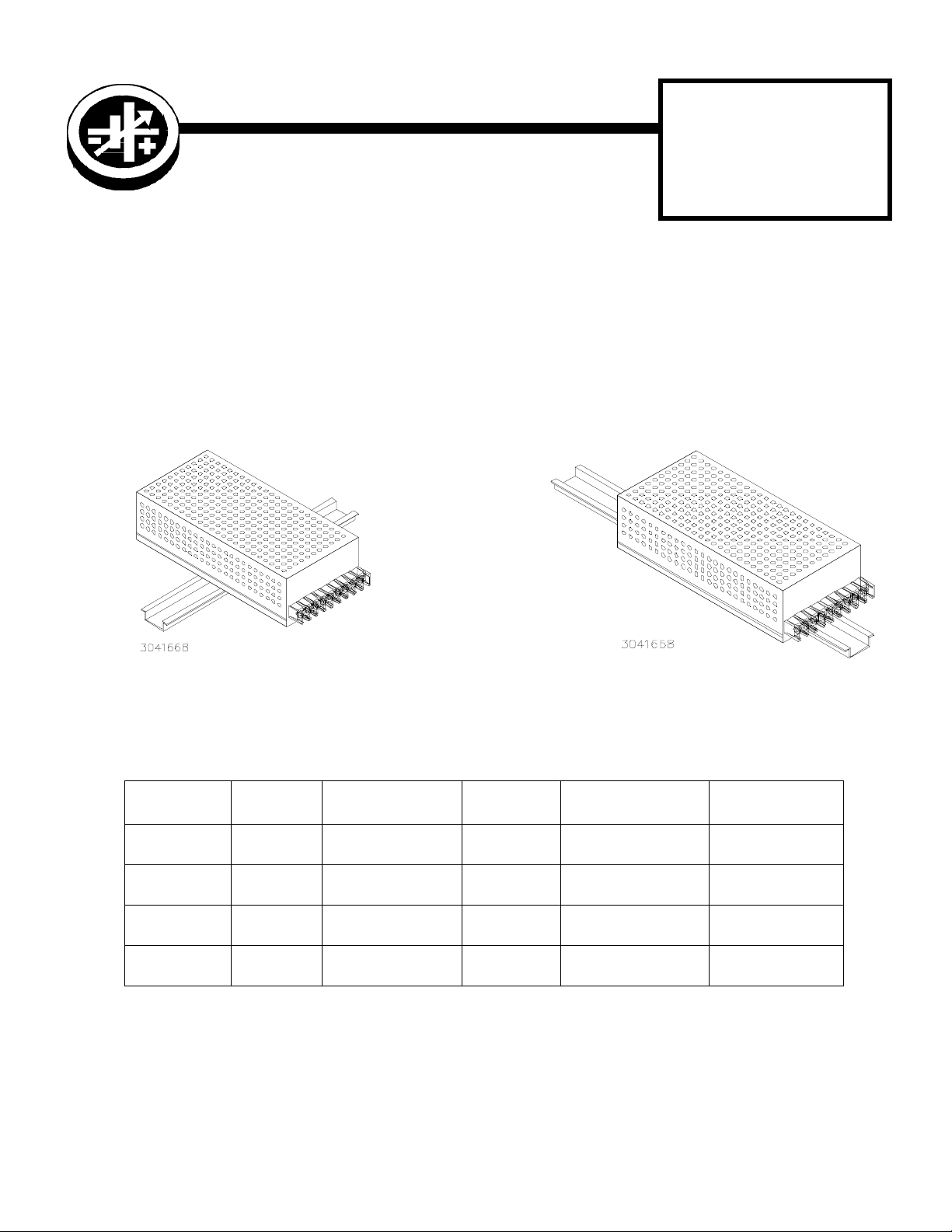
DESCRIPTION. Kepco KITs, Models DIN RKW-30L, -30S, 50L, and -50S each contain a cover, a mounting plate with
two clips and associated hardware used to install RKW Open Fram Series power supplies on a DIN rail. The -30 suffix
is for the 30 Watt Series, and -50 is for the 50 Watt Series. The “S” suffix is for mounting the power supply along the
short dimension (width) as shown in Figure 1, the “L” suffix is for mounting along the long dimension (length) as shown
in Figure 2.
FIGURE 1. S SUFFIX ORIENTATION FIGURE 2. L SUFFIX ORIENTATION
TABLE 1. COMPONENTS SUPPLIED
KIT
MODEL NO.
DIN RKW-30L CA 33 189-0797 108-0365
DIN RKW-30S CA 33 189-0796 108-0365
DIN RKW-50L CA 34 189-0794 108-0365
DIN RKW-50S CA 34 189-0795 108-0365
COVER
PART NO.
MOUNTING PLATE
PART NO.
CLIP (QTY 2)
PART NO.
SCREW (QTY 2)
PART NO.
101-0434
(M3 X 8, RHPH)
101-0434
(M3 X 8, RHPH)
101-0434
(M3 X 8, RHPH)
101-0434
(M3 X 8, RHPH)
WAS H ER (Q T Y 2)
PART NO.
103-0014
(NO. 4, INT. TOOTH)
103-0014
(NO. 4, INT. TOOTH)
103-0014
(NO. 4, INT. TOOTH)
103-0014
(NO. 4, INT. TOOTH)
KEPCO, INC. 131-38 SANFORD AVENUE FLUSHING, NY. 11352 U.S.A. TEL (718) 461-7000
©2003, KEPCO, INC
Data subject to change without notice
http://www.kepcopower.com email: hq@kepcopower.com
228-1463
FAX (718) 767-1102
1
Page 2
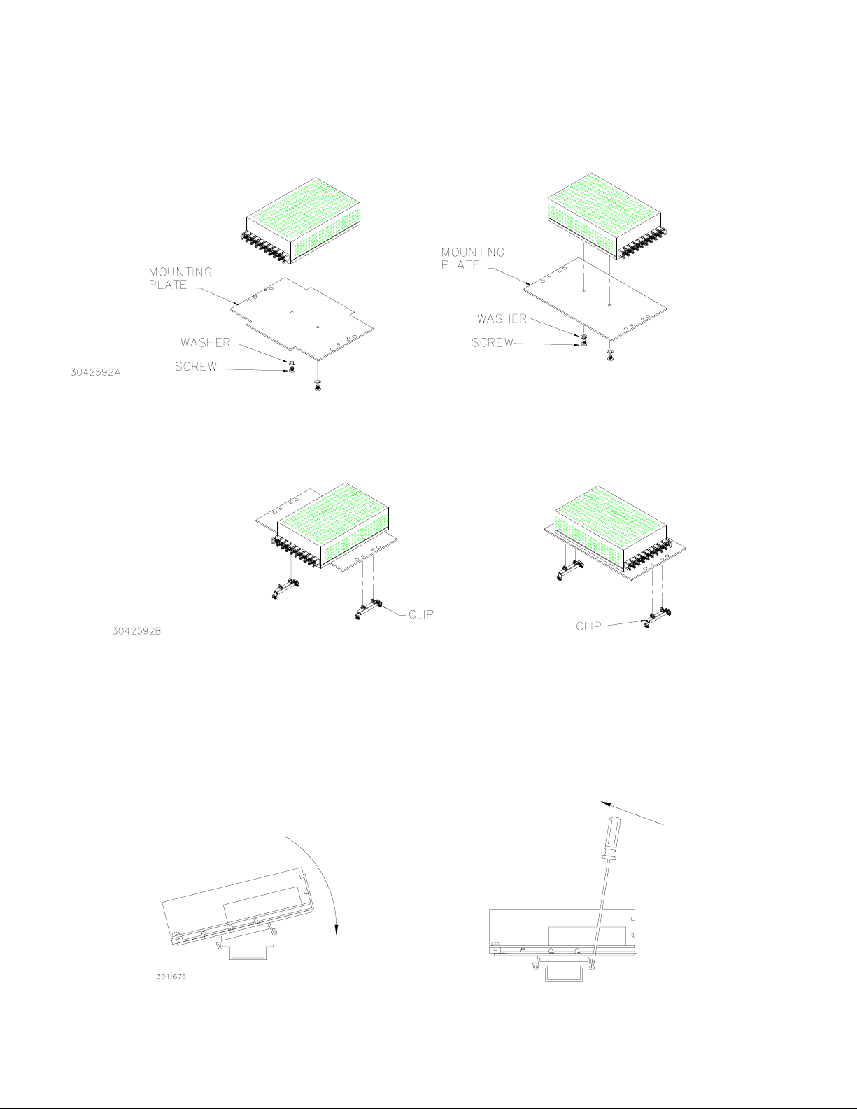
INSTALLATION
1. INSTALL COVER. Attach the cover to the power supply per instruction manual supplied with the cover.
2. INSTALL MOUNTING PLATE. Attach the mounting plate to the power supply using the hardware sup-
plied (see Figure 3).
L SUFFIX S SUFFIX
FIGURE 3. INSTALLING MOUNTING PLATE ON POWER SUPPLY
3. INSTALL CLIPS. Snap the two clips into the mounting plate holes (see Figure 4).
S SUFFIX L SUFFIX
FIGURE 4. INSTALLING CLIPS ON MOUNTING PLATE
4. INSTALL POWER SUPPLY ON DIN RAIL. To mount the power supply on the rail insert one end of both
clips under one edge of the rail, then snap the other end of the two clips into place (see Figure 5A).
REMOVING POWER SUPPLY FROM DIN RAIL. While grasping the power supply with one hand, Insert a screwdriver into the access holes provided and apply leverage towards the left as shown in Figure 5B to disengage
each clip from the rail. Where mounting clips are close together, it may be necessary to apply leverage with two
screwdrivers simultaneously.
INSTALLATION
A
B
REMOVAL
FIGURE 5. INSTALLATION AND REMOVAL OF POWER SUPPLY FROM DIN RAIL
KEPCO, INC. 131-38 SANFORD AVENUE FLUSHING, NY. 11352 U.S.A. TEL (718) 461-7000
2
http://www.kepcopower.com email: hq@kepcopower.com
228-1463 013003
FAX (718) 767-1102
 Loading...