

Page 1
INSTRUCTION MANUAL
KEPCO
An ISO 9001 Company.
KIT
DIN RKW-30P
DIN-RAIL MOUNTING KIT
FOR SERIES RKW 30W
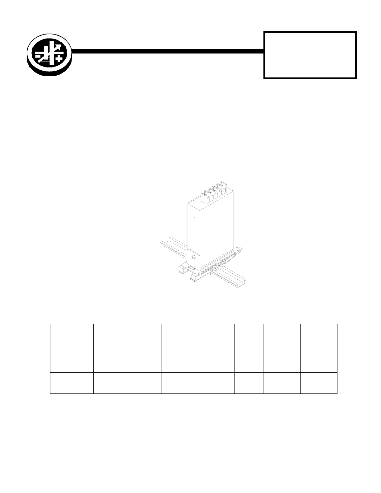
DESCRIPTION. Kepco KIT, Model DIN RKW-30P contains a cover, a mounting bracket with left and right preassem-
bled mounting clips and associated hardware used to install RKW Series power supplies on a DIN rail. The “P” suffix is
for mounting the power supply perpendicular to the DIN rail as shown in Figure 1. Outline Dimensions are shown in
Figure 5.
3042838
FIGURE 1. P SUFFIX ORIENTATION
TABLE 1. COMPONENTS SUPPLIED
SCREW
KIT
MODEL NO.
DIN RKW-30P CA 33-R 128-2154
KEPCO, INC. 131-38 SANFORD AVENUE FLUSHING, NY. 11355 U.S.A. TEL (718) 461-7000 FAX (718) 767-1102
©2010, KEPCO, INC 1
Data subject to change without notice 228-1483 REV 1
COVER
PAR T N O.
MOUNTING
BRACKET
PART NO.
http://www.kepcopower.com email: hq@kepcopower.com
(QTY 3)
(Power Supply
To Mounting
Bracket)
PAR T N O.
501-0062
(M3 x 8 PHPH)
CLIP
(QTY 2)
PART
NO.
108-0362 128-1938
CLIP
PLATE
(QTY 2)
PAR T
NO.
SCREW
Thread form
(QTY 4)
(Clip To
Mounting
Bracket)
PART NO.
101-0443
(4-40 X 1/4
PHPH)
WASHER
(QTY 4)
(Clip To
Mounting
Bracket)
PART NO.
103-0014
(NO. 4, INT.
TOOTH)
Page 2
INSTALLATION
1. INSTALL COVER. Attach the cover to the power supply per instruction manual supplied with the cover.
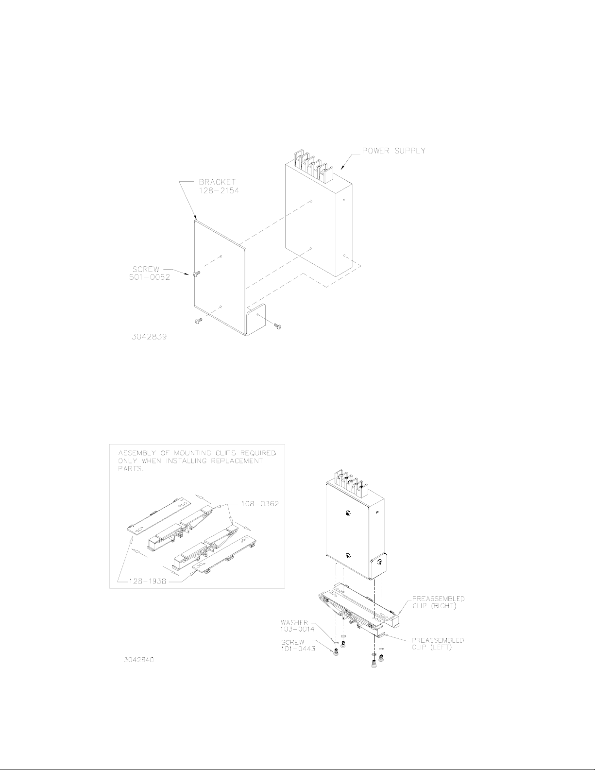
2. INSTALL MOUNTING BRACKET. Attach the mounting bracket to the power supply using the hardware
supplied (see Figure 2).
FIGURE 2. INSTALLING MOUNTING BRACKET ON POWER SUPPLY
3. INSTALL CLIPS. Attach preassembled mounting clips into the mounting bracket holes using hardware
supplied (see Figure 3).
FIGURE 3. INSTALLING CLIPS ON MOUNTING BRACKET
KEPCO, INC. 131-38 SANFORD AVENUE FLUSHING, NY. 11355 U.S.A. TEL (718) 461-7000 FAX (718) 767-1102
http://www.kepcopower.com email: hq@kepcopower.com
2 228-1483 REV 1 021210
Page 3

4. INSTALL POWER SUPPLY ON DIN RAIL. To mount the power supply on the rail insert one end of both
mounting clips under one edge of the rail, then snap the other end of the two clips into place (see Figure 4A).
INSTALLATION
A
B
REMOVAL
FIGURE 4. INSTALLATION AND REMOVAL OF POWER SUPPLY FROM DIN RAIL
REMOVING POWER SUPPLY FROM DIN RAIL. While grasping the power supply with one hand, Insert a screwdriver
into the access holes provided and apply leverage towards the left as shown in Figure 4B to disengage each clip from
the rail. Where mounting clips are close together, it may be necessary to apply leverage with two screwdrivers simultaneously.
KEPCO, INC. 131-38 SANFORD AVENUE FLUSHING, NY. 11355 U.S.A. TEL (718) 461-7000 FAX (718) 767-1102
021210 228-1483 REV 1 3
http://www.kepcopower.com email: hq@kepcopower.com
Page 4

FIGURE 5. RKW 30W POWER SUPPLY WITH KIT INSTALLED, OUTLINE DIMENSIONS
KEPCO, INC. 131-38 SANFORD AVENUE FLUSHING, NY. 11355 U.S.A. TEL (718) 461-7000 FAX (718) 767-1102
http://www.kepcopower.com email: hq@kepcopower.com
4 228-1483 REV 1 021210
 Loading...