

Page 1
OPERATOR’S MANUAL
RKE 1500W SERIES
POWER SUPPLY
SINGLE OUTPUT POWER SUPPLIES
SINGLE PHASE, POWER FACTOR CORRECTED
UNIVERSAL AC INPUT
KEPCO INC.
An ISO 9001 Company.
RKE 1500W SERIES
POWER SUPPLY
RKE 24-50K, RKE 36-42K, RKE 48-32K
IMPORTANT NOTES:
1) The contents of this manual are protected by copyright. Reproduction of any part can be
made only with the specific written permission of Kepco, Inc.
2) Data subject to change without notice.
MODEL
KEPCO®
©2013, KEPCO, INC
P/N 228-1514r5
KEPCO, INC. ! 131-38 SANFORD AVENUE ! FLUSHING, NY. 11355 U.S.A. ! TEL (718) 461-7000 ! FAX (718) 767-1102
email: hq@kepcopower.com ! World Wide Web: http://www.kepcopower.com
THE POWER SUPPLIER™
Page 2

TABLE OF CONTENTS
SECTION PAGE
1. Introduction........................................................................................................................................................ 1
1.1 Scope of Manual............................................................................................................................................. 1
1.2 Description...................................................................................................................................................... 1
2. Specifications .................................................................................................................................................... 1
3. Installation ......................................................................................................................................................... 1
4. Operation........................................................................................................................................................... 5
4.1 Voltage Adjustment......................................................................................................................................... 6
4.2 Remote Voltage Control ................................................................................................................................. 6
4.3 Remote Turn On-Turn Off............................................................................................................................... 7
5. Alarm Functions................................................................................................................................................. 7
5.1 POWER FAIL Signal (Optical Coupler Output Alarm Circuit) ......................................................................... 7
5.2 Overvoltage And Overtemperature Protection................................................................................................ 8
5.3 Overcurrent Protection.................................................................................................................................... 8
5.4 Fan Failure...................................................................................................................................................... 9
5.5 Undervoltage .................................................................................................................................................. 9
6. Load Connection ............................................................................................................................................... 9
6.1 Connecting The Load ..................................................................................................................................... 9
6.2 Parallel Connection......................................................................................................................................... 9
6.3 Series Connection ........................................................................................................................................ 11
6.4 Preliminary Electrical Check......................................................................................................................... 11
7. Fan Maintenance............................................................................................................................................. 12
LIST OF FIGURES
FIGURE TITLE PAGE
1 Mounting Positions For The RKE 1500W Power Supply ........................................................................... 1
2 Mechanical Outline Drawing Of The RKE 1500W Power Supply .............................................................. 2
3 Power Rating Vs. Temperature and Input Voltage..................................................................................... 3
4 Locations Of Operating Controls, Indicators and Terminals ...................................................................... 6
5 Connections For Remote Voltage Control ................................................................................................. 7
6 Output Alarm Circuit Optically Isolated ...................................................................................................... 8
7 RKE 1500W Power Failure Timing Diagram.............................................................................................. 8
8 Correct and incorrect Methods of Load Connection................................................................................... 9
9 Parallel Connection with Current Balancing............................................................................................. 10
10 Parallel Connection, Master-Slave, Multiple Loads.................................................................................. 10
11 Parallel Connection, Master-Slave, Single Load...................................................................................... 11
12 Series Connection.................................................................................................................................... 11
13 Functional Checkout ................................................................................................................................ 12
LIST OF TABLES
TABLE TITLE PAGE
1 Output Ratings and Specifications ............................................................................................................. 3
2 Power Supply Ratings and Specifications .................................................................................................. 4
3 Remote Voltage (RV) Adjustment Range ................................................................................................... 7
i RKW 1500W 021913
Page 3
1. INTRODUCTION
1.1 SCOPE OF MANUAL
This Operator's Manual covers the installation and operation of the Kepco RKE 1500W Series of PFC
(Power Factor Corrected), RoHS (Reduction of Hazardous Substances) compliant, switching power
supplies. For service information, write directly to: Kepco Inc., 131-38 Sanford Avenue, Flushing, New
York, 11355, U.S.A. Please state Model Designation and Serial Number of your RKE Power Supply.
This information can be found on the nameplate of the unit.
1.2 DESCRIPTION
The Kepco RKE 1500W Series consists of three models of switching power supplies, each with a single
output as shown in Table 1. Units include PFC (power factor correction) at the input and may be operated with a nominal 100V a-c to 240V a-c (input voltage range 85 to 265 Va-c), 50-60 Hz (input frequency range 47-66Hz). The RKE 1500W Series employs a light weight ferrite core with 135 KHz
switching frequency. Regulation is provided by pulse width modulation. A power stage with two MOSFETS on each side of the primary winding, operating in the forward mode, provides a smooth isolated
d-c output. A thyristor circuit prevents excessive turn-on current surge. Overvoltage protection and an
isolated remote TTL ON-OFF control are provided. An LED “output voltage ON” light and an output
voltage adjust trimmer are visible below the control terminals (left side of the case). Units are manufactured on a steel frame with a steel cover.
2. SPECIFICATIONS
Table 1 contains specifications and operating limits of individual RKE 1500W Series models. Table 2
contains specifications and operating limits common to all RKE 1500W Series Models. These specifications are at nominal input voltages at 25°C unless otherwise specified.
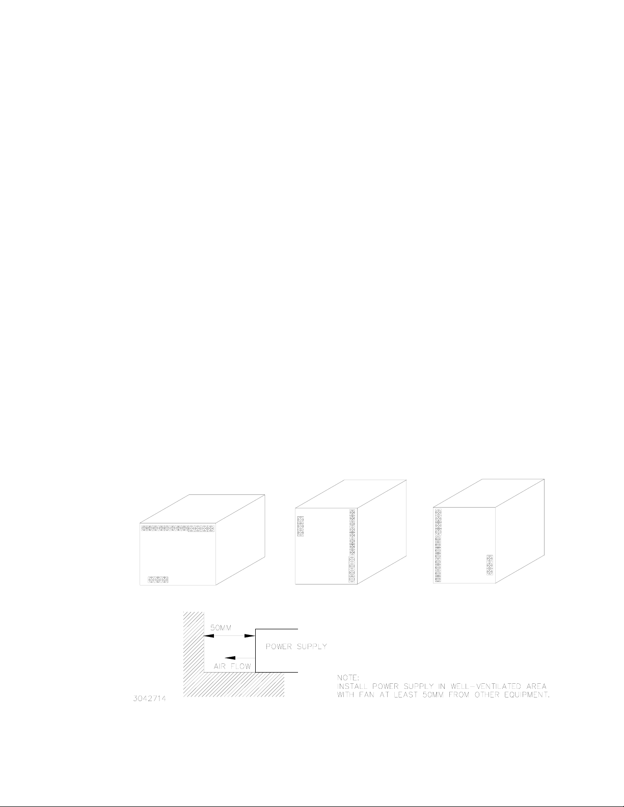
3. INSTALLATION
See Figure 1 for allowable mounting positions and orientation. See Figure 2 for mechanical outline
dimensions.
FIGURE 1. MOUNTING POSITIONS FOR THE RKE 1500W POWER SUPPLY
RKE 1500W 021913 1
Page 4
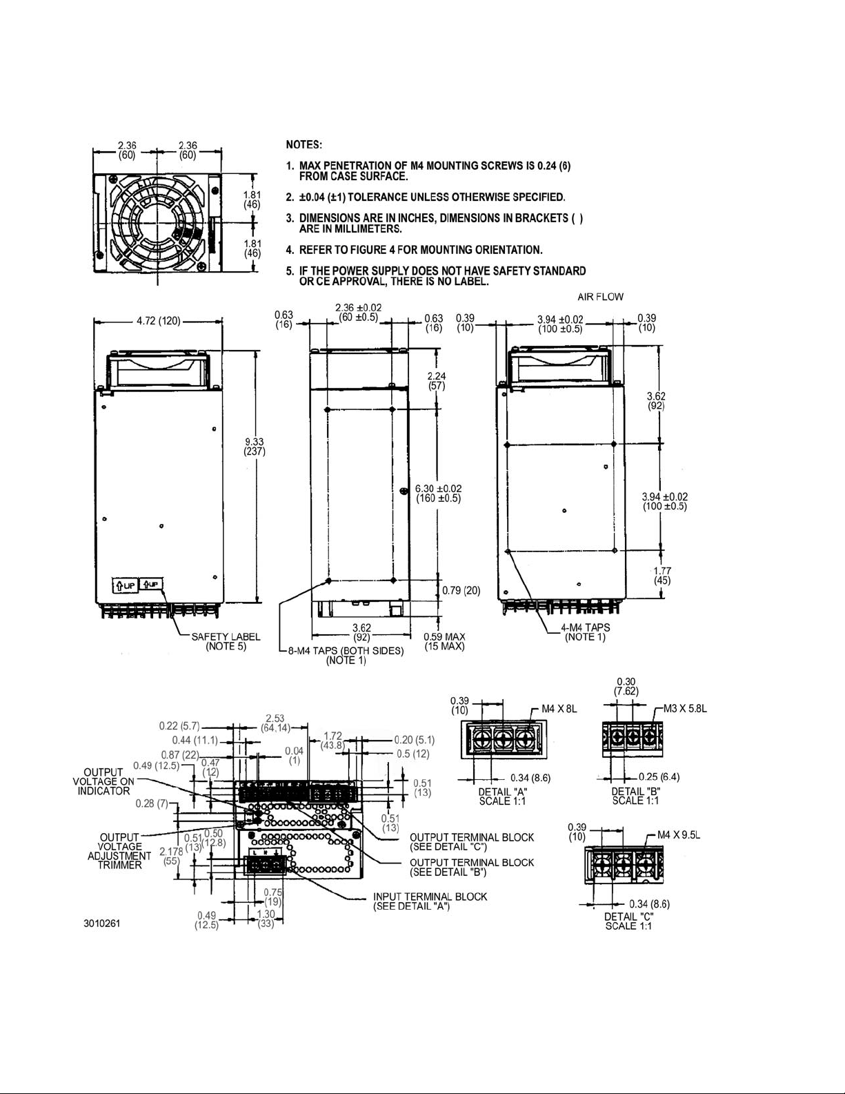
FIGURE 2. MECHANICAL OUTLINE DRAWING OF THE RKE 1500W POWER SUPPLY
2 RKE 1500W 021913
Page 5

TABLE 1. OUTPUT RATINGS AND SPECIFICATIONS
MODEL RKE 1500W 24-50K 36-42K 48-32K
Output Volts d-c
Adjustment Range (Volts d-c) 16.8-31.2 25.2-55.0 33.6-55.0
Voltage Setting (Volts d-c) 24 ±0.48 36 ±0.48 48 ±0.48
Maximum Output Ratings
(A,W)
(1)
85-90V a-c Input: 30-35A/720-840W N/A 16-19.2A/(768-922W)
85-95V a-c Input: N/A 21-25.2A/756-907W N/A
90-170V a-c Input: 35A/840W N/A N/A
95-170V a-c Input: N/A 25.2A/907W 19.2A/922W
170-265V a-c Input: 50A/1200W 42A/1512A 32A/1536W
Current Limit Setting
(2)
(Amps)
85 - 90V a-c input 31-57.5
90 - 170V a-c input 36-57.5
170 - 265V a-c input 52.5-57.5
Overcurrent Setting (Amps( 55-65 N/A 33.6-36.8
Current Short Circuit (Amps) 70 N/A 45
OVP Setting (Volts)
Low Output Voltage Protection Setting
(5)
14.4V(≤60% V
Efficiency% typical AC Input 100V 83 81 85
AC Input 200V 85 86 88
Ripple & Noise
(6)
(mV, p-p)
ripple 200 300 300
ripple noise 300 400 400
(1) See Figure 3 for power derating vs temperature and input voltage.
(2) Current limit value determined by the combination of input voltage and output voltage setting. For example, if RKE 48-23K is
operated at 120V a-c and output voltage is set at the minimum of output range (33.6V), current limit is closer to the maximum
specified value of 36.8A. For the same input voltage (120Vac) if output voltage is set at maximum (55.0V), then the current
limit value is closer to 20A (the minimum current limit value specified for input voltage range 90-170V a-c).
(3) Winker (intermittent) Operation; after cause is removed, output voltage restored automatically, however for some combina-
tions of input voltage and output voltage and current limit characteristics may be square type: see note (4) below.
(4) Square type. Unit first enters Current Limit; output voltage starts to drop (nearly square curve). If cause is removed while in
Current Limit, output voltage restores automatically. If current continues to increase, Overcurrent is triggered. If Overcurrent
is combined with an output voltage drop below 60% of rated output voltage (below 5V for 36V model), the unit shuts OFF;
recovery is by removing, then reapplying input power after approximately 30 seconds or by opening and (without waiting)
reclosing the RC terminals.
(5) When overvoltage is detected, output is shut OFF. Recovery is by removing, then reapplying input power after approximately
30 seconds or by opening and (without waiting) reclosing the RC terminals.
(6) Ripple and noise levels above are satisfied when conditions are 0 to 100% load, 0 to 65°C (load is derated from 50 to 65°C,
see Figure 3), and bandwidth ≤100MHz.
24V 36V 48V
(3)
(3)
(4)
22.3-48.3
26-48.3
44.1-48.3
(3)
(3)
(4)
17-36.8
20-36.8
33.6-36.8
32-35 56-60 56-60
Onom
)
≤5V
28.8V (≤60% V
(3)
(3)
(4)
Onom
)
24V MODEL
36 V MODEL
48 V MODEL
POWER RATING VS. TEMPERATURE
POWER RATING VS. INPUT VOLTAGE
FIGURE 3. POWER RATING VS. TEMPERATURE AND INPUT VOLTAGE
RKE 1500W 021913 3
Page 6

TABLE 2. POWER SUPPLY RATINGS AND SPECIFICATIONS
CHARACTERISTIC SPECIFICATION CONDITION/NOTES
Input Voltage Nominal 100-240V a-c, Range: 85-265V a-c (0 to 100% load, -10 to 65°C)
Range: 120-370 Vdc Polarity insensitive. Safety ratings apply
for a-c input operation only.
(0 to 100% load, -10 to 65°C)
Input Source Frequency Nominal: 50-60 Hz, Range 47-440 Hz. At 440 Hz, leakage current exceeds the
Input Current: (Maximum Load At
25°C with Nominal Output Voltage)
Input Protection A limiting resistor in series with a resistor fuse (and thyristor circuit) reduces start-up surge.
Input Surge cold start, interval > 30
sec ( First surge only, not including
current flow into EMI filter)
Leakage Current: 0.30mA typ., 0.75mA max. 120V a-c, 60Hz per IEC 950 and UL1950
Power Factor 0.99 typical 100V a-c, rated output
Transient Recovery excursion
characteristic recovery time
Stabilization
Source Effect (min - max) 0.1% Typical, 0.2% Maximum 85 to 132 V a-c, 170 to 265V a-c
Load Effect 1.0% Typical, 2.0% Maximum 0%-100% load change
Temperature Effect 0.5% Typical, 1.0% Maximum –10° to 65°C
Combined Effect ±1.6% Typical, ±3.2% Maximum Envelope, Source, Load and Temperature
Time Effect 0.2% Typical, 0.5% Maximum (8 hours at 25°C)
Start-up Time 300 msec Typical, 450 msec Maximum 100V a-c
12A rms max. (13A rms max. for 48V model) 100 - 120V a-c
10A rms max. (8A rms max for 24V model) 200 - 240V a-c
Units are protected against shorts by an input fuse. Fuse value 25.0A At 250 Volts
15A typ., 20A max. first surge 100 - 120V ac
30A typ., 40 max. first surge
0.60mA typ., 0.75mA max. 240V a-c, 60Hz per IEC 950 and UL1950
0.95 typical 200V a-c, rated output
±4% maximum
1 ms maximum
250 msec Typical, 400 msec Maximum 200V a-c
UL leakage safety specification limit
(0 to 100% load, -10 to 65°C)
200- 240 V ac
50% to 100% load,
transient time >50
µsec
Output Hold-up Time 10 msec Typical, 7 msec Minimum. 100V a-c
10 msec Typical, 7 msec Minimum. 200V a-c
Overvoltage Protection When the Power Supply goes into an overvoltage condition, the output is cut OFF. To restart
Low Output Voltage Protection If output falls to 60% of rated output (5V for 36V model) for approximately 30 Seconds and
Remote Control ON/OFF: "High", 2.4V to 24V (or open), unit OFF- Fan Off ; "Low", 0.0V to 0.4V (or closed), unit ON.
Operating Temperature: -10 to 65°C (see Figure 3.)
Startup Temperature -20 to -10°C (see Figure 3.)
Storage Temperature: -30°C to +75°C
(reset) the unit, it is necessary to remove the a-c input power, wait approximately 30 seconds,
and then reconnect the a-c input power. An alternative is to open and then reclose the RC terminals (no waiting time required).
overcurrent is triggered, the output is cut OFF. To restart (reset) the unit, it is necessary to
remove the a-c input power, wait approximately 30 seconds, and then reconnect the a-c input
power. An alternative is to open and then reclose the RC terminals (no waiting time required).
Source current is 1.6mA maximum at low level, and sink current is 1.0 mA maximum at high
level. The ±RC terminals are isolated from the a-c input terminal and the DC output terminals.
When remote ON/OFF is not in use, ±RC terminals must be shorted (use shorting link supplied) for unit to operate.
4 RKE 1500W 021913
Page 7

TABLE 2. POWER SUPPLY RATINGS AND SPECIFICATIONS (CONTINUED)
CHARACTERISTIC SPECIFICATION CONDITION/NOTES
Withstanding voltage : (at 15-35°C
ambient, 10-85% relative humidity)
Insulation Resistance: (at 25°C,
65% relative humidity)
Humidity: 10% to 95% relative humidity, noncondensing,
Vibration: 5-10 Hz., 10mm amplitude, 10-200 Hz., acceler-
Shock:
Safety: Approved by UL60950-1, CSA 22.2 No. 60950-1 (C-UL), and EN60950-1:2001 +A11 (TÜV),
EMC Emission - Conducted: Complies with FCC Class B, VCCI-Class B, EN55011-B, EN55022-B
EMC Emission - Radiated: Complies with FCC Class B, VCCI-Class B, EN55011-B, EN55022-B
EMC Emission - Input harmonics
current:
EMC Immunity Complies with EN50082-2
EMC Radiated susceptibility: Complies with EN61000-4-3 level 3 normal operation
EMC Conducted susceptibility: Complies with EN61000-4-6 level 3 normal operation
ESD: Complies with EN61000-4-2, level 4 normal operation
Electrical fast transient burst: Complies with EN61000-4-4 level 3 normal operation
Surge withstand: Complies with EN61000-4-5, level 4 No damage
Power Frequency Magnetic Field: Complies with EN61000-4-8, level 4 normal operation
Voltage dips interruptions and
variations
Dimensions: 3.62 in. (92 mm) x 4.72 in. (120 mm) x 9.33 in. (237 mm)
Mounting: Four No. M4 tapped holes on the sides and the bottom
Maximum Screw Penetration: 0.24 in. (6 mm)
Cooling: Forced air flow - fan
Frame Material/Cover Material: Steel
Weight 6.61 lbs, 3.0Kgs. maximum
2000Va-c for 1 minute. Cutout current is 20mA Between input and ground
500Va-c for 1 minute. Cutout current is 100mA Between output and ground
3000Va-c for 1 minute. Cutout current is 20mA Between input and output terminal
100 Megohms minimum (500Vdc) Between output and ground, input and
Wet Bulb temperature</=35°C
ation 64.3ft./s
Acceleration: 964.6ft./s
Pulse Duration: 11ms ± 5 msec
complying with Electrical Appliance and Materials Safety Laws (meeting the regulations of
creepage surface and spacial distance in item 8 of the Appendix). RKE 1500W units are CE
marked per the Low Voltage Directive (LVD), 73/23/EEC and 93/68/EEC. [The standards do
not apply with DC input operation]
Complies with EN61000-3-2
Complies with EN61000-4-11 normal operation
2
(19.6M/s2) (2g)
2
(294M/s2 ) (30g),
ground, and input and output,
operating and non-operating
non-operating 1 hr. on each of 3 axes,
sweep time 10 minutes
(non-operating, 1/2 sine pulse, three
shocks on each axis, Power Supply is
fixed on its bottom side)
4. OPERATION
Figure 4 shows the location of all operating controls and input/output terminals followed by an explanation of each. The unit is shipped with shorting links installed connecting the following terminals:
+RC to –RC and REF to RV
RKE 1500W 021913 5
Page 8

NOTE: If remote ON/OFF is not being used, ±RC terminals must be connected (use shorting link
supplied) for unit to operate.
LEGEND:
1. AC input terminals (L, N): Connect to AC, 100 to 240V,
input line.
2. Frame Ground (earth) terminal: Connect to earth ground.
This terminal is connected to the case.
3. DC output terminals (+, -): Connect to load (see Figure 8).
4. Signal Common (-COM): Provides return for REF and RV
signals
5. Reference Voltage (REF): Using the REF terminal
(together with the RV terminal), all the output voltages of
slave power supplies can be controlled by one voltage
adjustment of a master power supply (normally it is shorted
with a metal shorting link to the RV terminal).
6. Output Voltage Adjust (RV): This terminal (together with
the REF terminal) is used for remotely controlling output
voltage (see PAR. 4.2).
7. Current Balance (CB): This terminal is used when several
power supplies are connected in parallel (see PAR. 6.2).
8. Power failure (+PF, -PF): These terminals output an open
NOTE Unit is shipped with shorting links (not shown)
connecting +RC to –RC (see PAR. 4.3) and REF to
RV (see PAR. 4.2)
9. Remote ON-OFF (+RC, -RC): Output is turned ON-OFF by opening-shorting the RC terminals (output OFF when
open). RC terminals are isolated from input and output terminals. Normally, ±RC terminals are shorted with a metal
shorting link (see PAR. 4.3).
10. Output voltage adjustment trimmer (V.ADJ): Adjusts output voltage.
11. Output ON indicator: This green LED lights when output voltage is more than 80% of the programmed voltage.
logic signal if output voltage drops to 80% or lower of a set
voltage (5V or lower for 36V model), or if output voltage is
shut down due to overvoltage or current limit protection, fan
speed failure, or overheating. (see Figure 7).
FIGURE 4. LOCATIONS OF OPERATING CONTROLS, INDICATORS AND TERMINALS
4.1 VOLTAGE ADJUSTMENT
Output voltage can be manually adjusted with the voltage adjustment control, Vadj (see Figure 4). To
adjust voltage, first place the unit under an operating load, then monitor the (+) and (–) output terminals
with a precision voltmeter and turn the voltage control to the desired operating value. Refer to Table 1
for the recommended Adjustment Range of all the RKE 1500W Models
4.2 REMOTE VOLTAGE CONTROL
The unit is shipped with a shorting link in place between RV and REF terminals Removal of this link
allows the output voltage to be adjusted by either a trimmer pot (resistance) or by an external variable
voltage source across the RV terminal and COM terminal.
NOTE: Specifications are met when voltage is within adjustment range in Table 1. If remote voltage
control is not implemented, the shorting link between RV and REF must be in place
RESISTANCE: Use a shielded wire 6.6 feet (2M) maximum in length, for connection (of REF, RV, and
–COM terminals) to the trimmer control. Connect the external trimmer as shown in Figure 5 (A). Suggested value for the trimmer control is 5K ohms. With the external trimmer control at its maximum
clockwise position, set the output voltage to the desired maximum value by adjusting Vadj clockwise.
The output voltage adjustment range is from 70 to 130% for the 24V model, 17 to 153% for the 36V
model, and from 70 to 115% for the 48V model.
VOLTAGE. By adjusting an external 3.5 to 6.5V voltage source the 24V model can be adjusted from 70
to 130% of the nominal output. By adjusting an external 0 to 5.75 voltage source the 36V model can be
adjusted from 17% to 153% of the nominal output. By adjusting an external 3.5 to 5.75V voltage source
the 48V model can be adjusted from 70 to 115% of the nominal output. Remove the shorting link between
the REF and RV terminal. Connect the voltage source across the RV and –COM terminals as shown in
Figure 5 (B).
6 RKE 1500W 021913
Page 9

TABLE 3. REMOTE VOLTAGE (RV) ADJUSTMENT RANGE
RKE 24-50K RKE 36-42K RKE 48-32K
Remote Voltage RV (Volts) 3.5 - 6.5 0 - 5.75 3.5 - 7.5
Output Voltage, % of Vo (nomi-
nal)
70 - 130 17 - 153 70 - 115
A
FIGURE 5. CONNECTIONS FOR REMOTE VOLTAGE CONTROL
B
4.3 REMOTE TURN ON-TURN OFF
When power is ON at the source, the output may be turned ON or OFF with the remote control feature
using the ±RC terminals (see Figure 4). These terminals accept a logic level (2.4V to 24V “high” and
0.0 to 0.4V “low”), or a contact closure. When the ±RC terminals are open, using either a mechanical
switch or a high level logic signal, the RKE 1500W output is cut OFF. When the RC terminals are
shorted, the output returns to within specifications. At low level logic, the maximum source current is
1.6mA and at high level the sink current is 1.0mA. The RC terminals must remain shorted if remote ONOFF is not used. The RC terminals are isolated from both the AC input and DC output terminals.
5. ALARM FUNCTIONS
5.1 POWER FAIL SIGNAL (OPTICAL COUPLER OUTPUT ALARM CIRCUIT)
The default state of the alarm is logic low: the optocoupler conducts and the green front panel LED is
ON (see Figures 6 and 7). The sink current for the optocoupler is 50mA maximum, the maximum collector to emitter saturation voltage is 0.40 Volts, and the collector to emitter voltage is 40 volts maximum. When output voltage drops to less than 80% of programmed voltage (5V or less for 36V model),
PF circuit output goes HIGH (optocoupler output transistor in open state), and the front panel LED goes
OFF. The PF terminals are isolated from the AC and DC output input terminals. Insulation resistance
between the PF terminals and the AC input terminals is the same as the insulation resistance between
the input and output. Insulation resistance between the PF terminals and the output terminals is the
same as the insulation resistance between the output and ground.
RKE 1500W 021913 7
Page 10

FIGURE 6. OUTPUT ALARM CIRCUIT OPTICALLY ISOLATED
FIGURE 7. RKE 1500W POWER FAILURE TIMING DIAGRAM
5.2 OVERVOLTAGE AND OVERTEMPERATURE PROTECTION
When the output voltage of the RKE 1500W Power Supply increases beyond the specified values (see
Table 1), the output is cut OFF and the fan turns OFF. To restart (reset) the unit, remove AC input
power, wait approximately 30 seconds, then reconnect AC input power; or open the RC terminals and
then reclose the terminals.
When the internal temperature of the RKE 1500W Power Supply increases beyond the specified values
(see Table 1), the output is cut OFF and the fans turn OFF. The restart cycle (Power ON) should not
begin until the temperature returns to within specifications. To restart (reset) the unit, remove AC input
power, wait 40 seconds, then reconnect AC input power. The power supply cannot be reset using the
remote ON-OFF feature unless the power supply is first shut down for 30 seconds and then turned on
again.
The alarm circuit is a diode transistor optical coupler. The transistor is normally conducting. When the
alarm is activated, the transistor cuts off and the collector emitter circuit is open (see Figure 6)
5.3 CURRENT LIMIT/OVERCURRENT PROTECTION
From 170 to 265V a-c input, the output characteristic of the power supply is a square type, and the unit is
set to shut down if output current exceeds specifications (see Table 1) for more than 30 seconds and
undervoltage detection is present (see PAR. 5.5). From 85 to 170V a-c input, operation (including alarm
signals) is intermittent when current limit condition occurs. To restart (reset) the unit, remove AC input
8 RKE 1500W 021913
Page 11

power, wait 30 seconds, then reconnect AC input power. or open the RC terminals and then reclose the
terminals. (see PAR. 4.3).
5.4 FAN FAILURE
A cutoff of the fan supply voltage causes the output to shut down and the fans to turn OFF. Fan failure
and all the other protection circuit operations are indicated by an open circuit across the (±) PF terminals. To restart (reset) the unit remove the AC input power, wait 40 seconds, then reconnect AC input
power; or open the ±RC terminals and then reclose the terminals. If fan rotation is out of specification
the power supply will not recover.
5.5 UNDERVOLTAGE
If the output voltage of the power supply falls below 60 percent of the rated voltage for 30 seconds (5V
for the 36V model) while overcurrent is detected (see PAR. 5.3), the power supply shuts down and the
power failure alarm (see PAR. 5.1) will go to the high logic state. To restart (reset) the unit remove the
AC input power, wait 40 seconds, then reconnect AC input power; or open the ±RC terminals and then
reclose the terminals.
6. LOAD CONNECTION
6.1 CONNECTING THE LOAD
The load is connected across DC output (+) and (–) terminals (see Figure 8).
FIGURE 8. CORRECT AND INCORRECT METHODS OF LOAD CONNECTION
6.2 PARALLEL CONNECTION
RKE 1500W Power Supplies can be connected in parallel (with or without N+1 redundancy). The
impedance of the load wires between each power supply and load should be the same.
Figure 9 illustrates connection of up to four (maximum) power supplies in parallel. Output current for a
parallel connection operating into a single load is equalized by connecting the CB terminals as shown.
For a single remote ON-OFF signal to turn off all parallel-connected units, connect together all +RC terminals and connect together all –RC terminals (see PAR. 4.3).
The current equalization with up to four RKE 1500W units in parallel should be within 20 to 90% of the
total output current rating. The output voltage of any Power Supply individually must be within 2% maximum of the other power supply output voltage setting. The expected current sharing is such that the
output current variation for each power supply is less than or equal to 10% of each power supply rated
output current.
N+1 Redundancy. An N+1 system requires one additional power supply than necessary to supply the
load. If one of the parallel-connected units fail, the others will continue to provide power to the load
without down time. For redundancy, add isolation diodes as shown in Figure 9.
RKE 1500W 021913 9
Page 12

FIGURE 9. PARALLEL CONNECTION WITH CURRENT BALANCING
6.2.1 CURRENT BALANCING
For parallel operation (see Figures 9 or 11) the conditions for current equalization are:
Maximum Voltage Minimum Voltage–
------------------------------------------------------------------------------------------------------ - 2%=
The maximum output current: Rated output current of each power supply x (number of power supplies)
x (20 to 90 percent).
Variation of output current < ±10 % of each rated output current
Rated Voltage
variation of output voltage in each power supply
6.2.2 MASTER-SLAVE CONFIGURATIONS
Master-slave operation allows the output voltage of all the power supplies connected in parallel to be
adjusted at the same time by using the Vadj control on the designated master power supply.
6.2.2.1 MASTER-SLAVE, MULTIPLE LOADS
Figure 10 shows the master-slave connection of three power supplies in parallel, each having an independent load, with output voltage controlled by the Vadj control of the master power supply. Use
shielded wire for connections to RV terminals.
FIGURE 10. PARALLEL CONNECTION, MASTER-SLAVE, MULTIPLE LOADS
6.2.2.2 MASTER-SLAVE, SINGLE LOAD
Figure 11 shows the connection of three power supplies in parallel to a single load. The output voltage
of all power supplies is controlled by Vadj of the master. Current balancing is implemented to equalize
10 RKE 1500W 021913
Page 13

the load current (see PAR. 6.2.1). NOTE: Use shielded wire for connections to RV terminals. Match
impedance of load wires between each power supply and load by using the same wire lengths and wire
sizes.
FIGURE 11. PARALLEL CONNECTION, MASTER-SLAVE, SINGLE LOAD
6.3 SERIES CONNECTION
Units may be connected in series to obtain higher voltages. When a number of power supplies are
operating in series, the current rating is to be limited to the rating of the power supply with the lowest
rating. Each Power Supply in series should be protected by a diode connected in parallel with the output as shown in Figure 12. The diode protects against reverse voltages. It should be rated for typically,
V
REVERSE
>/= 2 x ΣV
of the series connection, I
OUT
FORWARD
>/= 2 xI
of the series connection).
OUT
FIGURE 12. SERIES CONNECTION
6.4 PRELIMINARY ELECTRICAL CHECK
Connect an adjustable load across the power supply DC output terminals, on the right side of the front
panel (see Figure 4). The load must have a dissipation rating of at least 3000 Watts. Connect a voltmeter and an oscilloscope across the power supply DC output (+) and (–) terminals. The oscilloscope
must be isolated from the source and grounded at the load. Use an isolation transformer between the
test equipment and the AC input power (see Figure 13).
Connect the AC input power to the line, neutral and ground terminals (see Figure 4). Turn source
power on and check the output voltage both with and without load. The output voltage can be adjusted
within the published range by using the front panel voltage control trimmer Vadj.
RKE 1500W 021913 11
Page 14

.
FIGURE 13. FUNCTIONAL CHECKOUT
7. FAN MAINTENANCE
Under most conditions the fan requires no maintenance. Do not use the fan in an environment of high
temperature and high humidity that exceeds the temperature and humidity limits given in the Power Supply Specifications (see Table 2). Avoid an environment where corrosive gas may be present. If the Power
Supply is used in an open or dirty area, a filter should be installed on the air intake side of the fan to prevent the inflow of dust particles. If the Power Supply is used in briny air care should be taken to keep the
salt from entering the Power Supply.
12 RKE 1500W 021913
 Loading...