

Page 1

OPERATOR’S MANUAL
RCW 1500W SERIES
POWER SUPPLY
SINGLE OUTPUT, UNIVERSAL INPUT
KEPCO INC.
An ISO 9001 Company.
IMPORTANT NOTES:
1) The contents of this manual are protected by copyright. Reproduction of any part can be
made only with the specific written permission of Kepco, Inc.
2) Data subject to change without notice.
SINGLE PHASE, 0.99 POWER FACTOR
MODEL
RCW 1500W SERIES
POWER SUPPLY MODELS
RCW 3.3-300K, RCW 5-300K, RCW 12-125K,
RCW 15-100K, RCW 24-65K, RCW 28-55K,
RCW 48-32K
KEPCO®
©2007, KEPCO, INC
P/N 228-1502R1
KEPCO, INC. ! 131-38 SANFORD AVENUE ! FLUSHING, NY. 11355 U.S.A. ! TEL (718) 461-7000 ! FAX (718) 767-1102
email: hq@kepcopower.com ! World Wide Web: http://www.kepcopower.com
THE POWER SUPPLIER™
Page 2

TABLE OF CONTENTS
SECTION PAGE
1.0 Introduction.............................................................................................................................................. 1
1.1 Scope of Manual ..................................................................................................................................... 1
1.2 Description .............................................................................................................................................. 1
2.0 Specifications .......................................................................................................................................... 1
3.0 Operation................................................................................................................................................. 4
3.1 Installing The Power Supply .................................................................................................................... 4
3.2 Connecting The Load (Local Sense) ...................................................................................................... 7
3.3 Connecting The Load (Remote Sense) .................................................................................................. 7
3.4 Voltage Adjustment ................................................................................................................................. 7
3.5 Remote Voltage Control .......................................................................................................................... 8
3.6 Remote Turn-on Turn-off......................................................................................................................... 9
3.7 Parallel Operaton .................................................................................................................................... 9
3.8 Master/Slave Operation......................................................................................................................... 11
3.9 Preliminary Electrical Check.................................................................................................................. 11
4.0 Alarm Functions .................................................................................................................................... 13
4.1 Overvoltage And Overtemperature Protection ...................................................................................... 13
4.2 Undervoltage Protection........................................................................................................................ 14
4.3 PF Input Power Failure.......................................................................................................................... 14
4.4 Fan Failure ............................................................................................................................................ 15
5.0 Fan Replacement .................................................................................................................................. 15
6.0 Fan Maintenance................................................................................................................................... 15
LIST OF FIGURES
FIGURE TITLE PAGE
1 RCW 1500W Power Supply Peak To Peak Input Surge Current For T<50us ........................................... 3
2 Percent Power Rating Versus Ambient Temperature ................................................................................. 4
3 Mechanical Outline Drawing OfThe RCW 1500W Power Supply ............................................................. 5
4 Mounting Positions For The RCW 1500W Power Supply ........................................................................... 6
5 Connections For Remote Sensing With The RCW 1500W Power Supply.................................................. 7
6 Terminal Locations Of The RCW 1500W Power Supply............................................................................. 8
7 Connections For Remote Voltage Control Of The RCW 1500W Power Supply ......................................... 9
8 Parallel Connection of Three RCW Power Supplies ................................................................................ 10
9 Functional Checkout Of The RCW 1500W Power Supply ....................................................................... 12
10 Logic Alarm Optical Coupler Output For The RCW 1500W Power Supply ............................................... 13
11 Timing Diagrams For The RCW 1500W Power Supply ............................................................................ 14
LIST OF TABLES
TABLE TITLE PAGE
1 Power Supply Ratings And Specifications ..................................................................................................1
2 Power Supply Ratings and Specifications ..................................................................................................2
RCW 1500W 120607 i
Page 3

1.0 INTRODUCTION
1)
The P
1.1 SCOPE OF MANUAL
This Operator's Manual covers the installation and operation of the Kepco RCW 1500W Series of
Switching Power Supplies. For service information, write directly to: Kepco Inc., 131-38 Sanford
Avenue, Flushing, New York, 11355, U.S.A. Please state Model Designation and Serial Number of
your RCW Power Supply. This information can be found on the nameplate of the unit.
1.2 DESCRIPTION
The Kepco RCW 1500W Series consists of seven models of Switching Power Supplies, with a single output as shown in Table 1. RCW power supplies are compliant with the Low Voltage Directive
(LVD) and carry the CE Mark. Units are designed to operate with a universal input voltage within the
range of 85 to 264V AC and may be operated with either 100-120V AC, or 200-240V AC, 50-60 Hz
(47-66 Hz) input. They will also operate on 125V to 370V dc input. The RCW 1500W Series
employs a light weight ferrite core transformer with 150 KHz typical switching frequency. The
Power Factor Correction Circuit has a typical switching of 80 KHz. Regulation is provided by pulse
width modulation. A FET power stage, operating in the forward conversion mode provides a
smooth isolated dc output. A resistor and thyristor "soft-start" circuit prevents excessive turn-on
current surge. Overvoltage protection and optically isolated remote TTL ON-OFF control are provided. Current limiting with automatic recovery from short circuit is featured. Units are enclosed in a
wrap-around aluminum case with a green LED "output present" light visible on the terminal side of
the case.
2.0 SPECIFICATIONS
Table 1 contains specifications and operating limits of individual RCW 1500W Series models. Table
2 contains specifications and operating limits common to all RCW 1500W Series Models. These
specifications are at nominal input voltages at 25°C unless otherwise specified.
TABLE 1. POWER SUPPLY RATINGS AND SPECIFICATIONS
MODEL RCW 1500W 3.3-300K 5-300K 12-125K 15-100K 24-65K 28-55K 48-32K
Output Volts d-c
Adjustment Range
Maximum
Output
Ratings
(Amps/
Watts
Current Limit (Amps)
OVP Settings (Volts)
Efficiency %
typical
Ripple &
(3)
Noise
(mV, p-p)
Transient
Recovery
(5)
50°C, amb A
50°C, amb W
60°C, amb A
60°C, amb W
70°C, amb A
70°C, amb W
AC Input 120V 70 75 76 76 78 79 80
AC Input 240V 73 80 81 81 82 83 84
output ripple (max) 100 100 100 100 100 100 100
spike noise (max)
Recovery to
1%(<ms)
(6)
Excursion ±V max
(7)
(1)
(2)
3.3V 5V 12V 15V 24V 28V 48V
1.8-3.5 3.5~5.5 8.4~13.2 12.0~16.5 16.5~26.4 25.2~30.8 30.8~52.8
300 300 125
1050 1500 1500
210 210 87.5 70A 45.5 38.5 22.4
735 1050 1050 1050 1092 1078 1075.2
120 120 50 40 26 22 12.8
420 600 600 600 624 616 614.4
315-350 315-350 130-140 105-115 68-72 57.7-63.2 33.6-36.8
3.96-4.62 6.0-7.0 13.2-15.6 16.5-19.5 26.4-31.2 30.8-36.4 49.44-59.04
(4)
200 200 200 200 200 200 300
111111 1
1.0 1.0 1.0 1.0 1.0 1.0 1.0
100
1500
65 55 32
1560 1540 1536
ower Supply has a square type overcurrent characteristic, shutdown by undervoltage detection
2)
The Power Supply has a shut-down type (by tracking) overvoltage characteristic. Recovery time to reset 40 seconds minimum
3)
Source component 2x source frequency and switching component approximately 150 KHz, 10 to 100% load and ambient Ta = 25°C
4)
Measure with a 50MHz bandwidth, 10 to 100% load and ambient Tc= 25°C
5)
Output voltage setting = ±1%
6)
A step load change from 50% to 100% of rated load current (with the following tr, tf load changes) produces no more than the output
voltage excursions listed in the above table. The load change will be 5A/µs for Io>20A and 1A/µs for I<20A tr, tf of load change: 3.3v and
5v>30µs, 12v>12.5µs, 15v>10µs, 24v>6.5µs, 28v>5.5µs, 48v>3.2µs,
7)
Recommended (using internal adjustment pot, par. 3.4). Using external pot (par.3.5) range = 10% to 110% of rated output voltage.
RCW 1500W 120607 1
Page 4

TABLE 2. POWER SUPPLY RATINGS AND SPECIFICATIONS
SPECIFICATION DESCRIPTION
Input Voltage Nominal: 100-120Vac or 200-
240Vac
Range 125-370 Vdc Polarity insensitive. Safety ratings apply for a-c
Input Source Frequency Nominal 50/60 Hz, Range 47-440 Hz. (At 440 Hz the leakage current exceeds the
VDE safety leakage specification limit).
Brownout Voltage 80 V ac min
Input Current: (Maximum Load At 50°C with
Nominal Output Voltage)
120V ac
240V ac
Input Protection Units Are Protected Against Shorts By An Input Fuse. Fuse Value 30.0A At 250
Volts
Input Surge at 25° C from cold start; resistor
and thyristor soft start circuit reduces start-up
surge. (see Figure1)
120V ac 20.0A max. first surge
240V ac
Stabilization Typical Maximum
Source Effect (min - max) (85 to
132 V ac, 170 to 264V ac)
Load Effect, measured at sensing terminals (0%-100% load
change)
Temperature Effect (–10° to
71°C)
Combined Effect (envelope,
Source, Load and Temperature)
Drift (8 hours at 25°C) 0.2% 0.5%
Transient Rec’y Test Conditions
MODEL / tr, tf of load change
≥ µs
3.3V/30µs, 5V/30µs, 12V/12.5µs, 15V/10µs, 24v/6.5µs, 28V/5.5µs. 48V/3.2µs
Output Holding Time: Output is maintained for 30 milliseconds typical upon input interruption (20 milli-
seconds minimum) with nominal 120 volts AC input voltage and output load at
50°C current rating.
Start-up Time 900 msec maximum, 600 typical.
Overvoltage Protection When the Power Supply goes into an overvoltage condition, the output is cut OFF.
To restart (reset) the unit, it is necessary to remove the AC input power, wait 40
seconds, and then to reconnect the AC input power.
Operating Temperature: -10 to 71°C (see Figure 2)
Storage Temperature: -30°C to +75°C
Humidity: 10% to 95% relative humidity, noncondensing, Wet Bulb temperature<35°C
Isolation
(at 25°C ambient, 65% relative humidity)
Between input and case, 2500Vac for 1 minute
Between input and output terminal, 2500Vac for 1 minute. Cutout current is
20mA
Insulation Resistance: (at 25°C, 65% relative
humidity)
Between output and case, input and case, and input and output, 100 Megohms
minimum (500Vdc)
Leakage Current: 1.0 mA max at 120 Vac (U.L. Method 50 to 60 Hz)
2.0 mA max at 240Vdc (VDE Method 50 to 60 Hz, two terminal connection)
Range: 85-264 Vac
input operation only.
22A RMS max., and 16A RMS max for the
3.3V output model
11A RMS max., and 8A RMS max for the 3.3V
output model
40.0A max. first surge
0.05%
0.2%
(1)
(2)
0.1%
0.3%
(1)
(2)
0.5% 1.0%
± 0.7% ± 1.5%
2 RCW 1500W 120607
Page 5
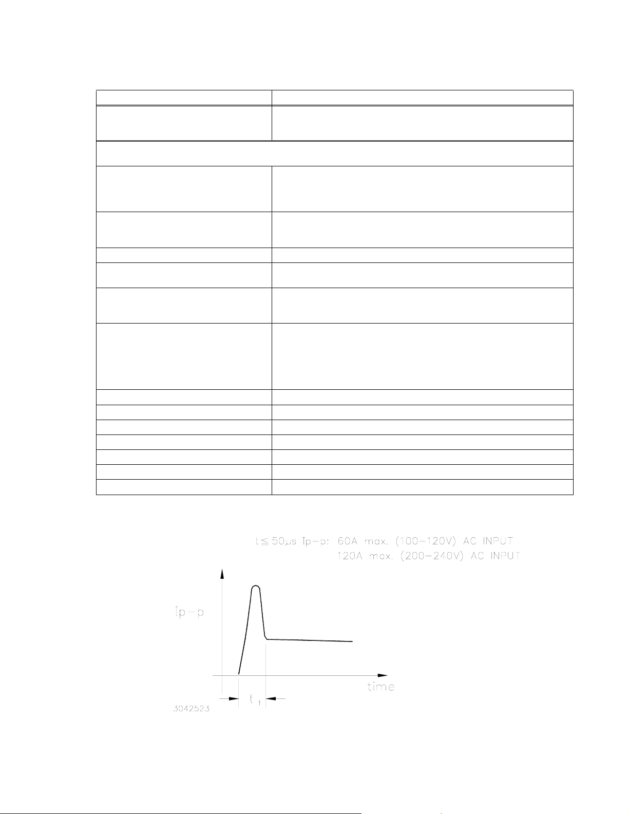
TABLE 2. POWER SUPPLY RATINGS AND SPECIFICATIONS (CONTINUED)
SPECIFICATION DESCRIPTION
Vibration:
(non-operating 1 hour on each of three axes,
5-10 Hz., 10mm amplitude, 10-200 Hz., 64.3ft./s
2
( 19.6M/s2)
Power Supply is fixed on its bottom side)
1) 2 mV typ,4mV maximum for the 3.3 volt Model
2) 10mV typ,15mV maximum for the 3.3 volt Model
Shock:
(non-operating, 1/2 sine pulse, three shocks
964.6ft./s
2
(294M/s2 ), 11ms ± 5 msec pulse duration
on each axis, Power Supply is fixed
on its bottom side)
Input Transient: The RCW Power Supply (with a 50 ohm termination) should operate trouble free
when a 1us, 2K Volt, 50–60 Hz input is applied between the input and ground terminals.
EMI Conducted: FCC Class A
Safety: UL 1950 Recognized, CSA Electrical Bulletin 22.2, No. 234, Level 5 Certified and
EN 60 950 (TUV) Approved, CE marked per Low Voltage Directive (LVD)
Remote Error Sensing: The RCW 1500W Power Supply will compensate up to 0.15 Volts max per load
wire for the RCW 3.3-300K, and up to 0.25 Volts per load wire for the RCW
5-300K, and up to 0.4 Volts per load wire for all other RCW Models (see Figure 5).
Remote Control ON/OFF: "High", 2.4V to 24V (or open), unit ON
"Low", 0.0V to 0.4V (or closed), unit OFF- Fan Off
Source current is 1.6mA maximum
The (±)RC terminals are isolated from the AC input terminal and the DC output
terminals. Under normal conditions the (±)RC terminals are high, so when the
function is not used the terminals should be left open.
Power Factor 0.99 typical, satifies EN61000-3-2 Requirements
Dimensions: 4.33 in. (110 mm) x 7.99in. (203 mm) x 8.66 in. (220 mm)
Mounting: No. M4x8 tapped holes
Maximum Screw Penetration: 0.24 in. (6 mm)
Cooling: Forced air flow - two fans
Frame Material/Cover Material: Aluminum
Weight: 16.53lbs. (7.5 Kg)
RCW 1500W 120607 3
Page 6

FIGURE 1 RCW 1500W POWER SUPPLY PEAK TO PEAK INPUT SURGE CURRENT FOR T<50US
FIGURE 2 PERCENT POWER RATING VERSUS AMBIENT TEMPERATURE
3.0 OPERATION
3.1 INSTALLING THE POWER SUPPLY
The unit may be mounted in accordance with the Mechanical Outline Drawing, Figure 4 (mounting
holes are provided). The temperature of the air surrounding the Power Supply must not exceed the
ambient values given in the Specifications Table 1. See Figure 3 for horizontal and vertical mounting of the RCW 1500W Power Supply.
The RCW 1500W has four tapped Metric M4x8L mounting holes on the bottom side of the unit for
horizontal installation as well as eight tapped Metric M4x8L mounting hole on the side surfaces for
vertical installation. Free air space must be provided at the rear of the unit to allow for maximum
ventilation and exhaust of the fans. Power Supply specifications should be derated for certain operating temperatures (refer to Table 2).
Referring to Figure 3, the air cooling holes on the front panel of the unit and the front of the fan and
on the top cover should be kept clear at least 1 inch (20mm) from adjacent equipment and in a well
ventilated a rea.
4 RCW 1500W 120607
Page 7

FIGURE 3 MOUNTING POSITIONS FOR THE RCW 1500W POWER SUPPLY
RCW 1500W 120607 5
Page 8

FIGURE 4 MECHANICAL OUTLINE DRAWING OFTHE RCW 1500W POWER SUPPLY
6 RCW 1500W 120607
Page 9

3.2 CONNECTING THE LOAD (LOCAL SENSE)
To connect the load for local sensing, the shorting links must be maintained between the (+) S and
(+) M terminals, and between the (–) S and (–) M terminals. The load is connected across the DC
output (+) and (–) terminals.
3.3 CONNECTING THE LOAD (REMOTE SENSE)
The load is connected as shown in Figure 5. Error sensing may be done at the load terminals to
compensate for voltage loss in the connecting wires. The shorting links must be removed from the
(±) S Sense terminals.
FIGURE 5 CONNECTIONS FOR REMOTE SENSING WITH THE RCW 1500W POWER SUPPLY
3.4 VOLTAGE ADJUSTMENT
The unit is provided with a voltage adjustment control (Vadj) (see Mechanical Outline Drawing, Figure 4). To adjust voltage, first place the unit under an operating load, then monitor the (+) S and (–)
S Sense terminals with a precision voltmeter and turn the voltage control to the desired operating
value. Refer to Table 1 for the recommended Adjustment Range of all the RCW 1500W Models
(see Figure ).
NOTE: Actual output voltage can exceed recommended range values.
RCW 1500W 120607 7
Page 10

LEGEND:
1. AC Input (Neutral)
2. AC Input (Hot)
3. No Connection
4. Ground
5. DC Output (–)
6. DC Output (+)
7. REF (Reference Voltage)
8. (–) S (Remote Sense)
9. (–) M (Output Voltage Monitor)
10. (+) M (Output Voltage Monitor)
11. (+) S (Remote Sense)
12. ON (Output voltage ON LED, green)
13. V. ADJ (Output Voltage Adjustment)
14. OV (Output overvoltage LED, red)
15. UV (Output undervoltage LED, red)
16. FAN (Fan alarm LED, red)
17. (+) RC (Remote ON-OFF)
18. (–) RC (Remote ON-OFF)
19. (+) AL (Alarm OV, UV, Thermal, )
20. (+) PF (Alarm- Input Power Fail)
21. (–) AL, (–) PF (Alarm common))
22. CB (Current Balance)
23. RV (Output voltage variable)
FIGURE 6 TERMINAL LOCATIONS OF THE RCW 1500W POWER SUPPLY
3.5 REMOTE VOLTAGE CONTROL
The use of the RV terminal allows the output voltage to be adjusted by a trimmer pot or by an external source.
Use a shielded wire, 2m maximum in length, for connection to the trimmer control. Maintain the
shorting link between the (+) S and (+) M terminals, and between the (–) S and (–) M terminals,
remove links between REF and RV terminals and connect the external trimmer between the
REF,RV, and (–) M and (–) S terminals (with the center lead of the trimmer going to the RV terminal, see Figure 7). Suggested value for the trimmer control is 5K ohms. With the external trim-
8 RCW 1500W 120607
Page 11

mer control at its maximum clockwise position set the output voltage to the desired
maximum value by adjusting the Vadj clockwise. The value should not be more than 110%
Eo nominal.
By using an external 0-5.5V voltage source the maximum output voltage can be adjusted from 0 to
110%. For voltage source use remove the shorting link between the REF and RV terminal. Connect
the voltage source across the RV and (–)S terminals. The impedance of the load wires connecting
each power supply to the load should be the same when using remote sensing with this configuration. It is possible that the overvoltage protection may be triggered if the external programming voltage source is changed very quickly when the power supply is at a low load condition
By adjusting the external control from minimum to maximum, the output voltage will change from
minimum to maximum value (0% to 110% of Eomax).
NOTE: Specifications are met when voltage is within adjustment range in Table 1. If remote
voltage control is not implemented, the shorting link between RV and REF must be in
place:
VOLTAGE CONTROL
BY TRIMMER
VOLTAGE CONTROL
BY EXTERNAL
PROGRAMMABLE SOURCE
FIGURE 7 CONNECTIONS FOR REMOTE VOLTAGE CONTROL OF THE RCW 1500W POWER SUPPLY
3.6 REMOTE TURN-ON TURN-OFF
When power is ON at the source, the output may be turned ON or OFF with the remote control feature. The remote ON/OFF RC (Remote Control) terminals can be controlled by a logic level (2.4V
to 24V "high" and 0.0 to 0.4V "low"), or a contact closure. When the RC terminals (on the front
panel) are short circuited by using either a mechanical switch or a low level logic signal, the RCW
1500W output is cut OFF. At low level logic, the maximum sink current is 1.6mA. With the RC terminals open the RCW 1500W output returns to within specifications. The RC terminals should remain
open if not used (see Figure ).
The RC terminals are isolated from the AC input and DC output terminals.
RCW 1500W 120607 9
Page 12

3.7 PARALLEL OPERATON
-
Identical RCW 1500W Power Supplies can be connected in parallel (see Figure 8). The output current of each Power Supply can be balanced by connecting together all the CB terminals, connecting together all the -S terminals and connecting together all the +S terminals of up to four 1500W
Power Supply units (see Figure 8 for three units). The current tolerance with up to four RCW
1500W units in parallel should be within (±) 10% of the rated output current. With four RCW 1500W
units in parallel, the output voltage of any Power Supply individually must be within 2% of the other
power supply output voltages. The output current range is 20 to 90% of the nominal output current.
NOTES
1) Remove the connecting links between the (+) M and (+) S terminals and between the (–) M and (–) S terminal. Maintain the con
necting links between the REF and RV terminals.
2) Set voltage of unit 1 to the desired voltage at the load.
3) With three RCW 1500W units in parallel the output voltage of each Power Supply must be set to less than 2% of each other
4) When the Current Balance function is used with the Remote ON/OFF function, connect all the (+) RC terminals together and all
the (–) RC terminals together.
5) Use the same length and wire size for load connecting wires from the (+) and (–) Bus Bar of each RCW 1500W Power Supply to
the load terminals
6) Use the same length and wire size for twisted pair Sensing wires from the (+) S and (–) S terminals of each RCW 1500W power
Supply to the load terminals
FIGURE 8 PARALLEL CONNECTION OF THREE RCW POWER SUPPLIES
10 RCW 1500W 120607
Page 13

The conditions for current equalization are:
Maximum Voltage Minimum Voltage–
------------------------------------------------------------------------------------------------------ - 2%=
Rated Voltage
Output current is 20 to 90% of the total rated output current
The maximum output current: Rated output current x (number of power supplies) x (0.9 max).
Four units are the maximum allowed.
When the current balance function is used together with the Remote ON/OFF function, connect
together all the (+) RC terminals and connect together all the (–) RC terminals.
3.8 MASTER/SLAVE OPERATION
To adjust all output voltages at the same time by only one V. ADJ. control on the Master Power
Supply (and when using multiple loads),remove the link between the REF to RV terminals on the
Slave Power Supplies: Maintain the links between the (+) S and (+) M terminals and between the
(–) S and (–) M terminals of the Master and Slave units, and connect all the (–)S terminals together,
and connect all the CB terminals together, and all the RV terminals together of the Master and
Slave units. Connect all the (+) output terminals to the (+) load terminal, and all the (–) output terminals to the (–) load terminal.
3.9 PRELIMINARY ELECTRICAL CHECK
Connect an adjustable load across the power supply output terminals, on the center bus bars (on
the front panel, see Figure 9). The load must have a dissipation rating of at least 3000 Watts. Connect a voltmeter and an oscilloscope across the power supply Monitor terminals, (+) M and (–) M,
located on the right side terminal block (on the front panel). The oscilloscope must be isolated from
the source and grounded at the load. Use an isolation transformer between the test equipment and
the AC input power (see Figure 9).
Connect the AC input power to the line, neutral and ground terminals of the left side terminal barrier strip (on the front panel). Turn the unit ON and check the output voltage with and without
load. The output voltage can be adjusted within the published range by using the front panel voltage control trimmer.
RCW 1500W 120607 11
Page 14

FIGURE 9 FUNCTIONAL CHECKOUT OF THE RCW 1500W POWER SUPPLY
12 RCW 1500W 120607
Page 15

4.0 ALARM FUNCTIONS
4.1 OVERVOLTAGE AND OVERTEMPERATURE PROTECTION
When the output voltage or the internal temperature of the RCW 1500W Power Supply increases
beyond the specified values (see Table 2), the output is cut OFF and the fan turns OFF. To restart
(reset) the unit it is necessary to remove the AC input power, wait 40 seconds and then to reconnect the AC input power. Another way to reset the power supply is to short circuit the (±) RC terminals and then open the terminals. However, when the Power Supply shuts down due to an increase
in internal temperature, the restart cycle (Power ON) should not begin until the temperature returns
to within specifications. Indication of an overvoltage or overtemperature condition is provided by a
red LED and a logic alarm output (at the (±) AL terminals) The alarm circuit is a diode transistor
optical coupler. The alarm is activated when the collector emitter circuit is open (see Figures 10
and 11).
FIGURE 10 LOGIC ALARM OPTICAL COUPLER OUTPUT FOR THE RCW 1500W POWER SUPPLY
RCW 1500W 120607 13
Page 16

FIGURE 11 TIMING DIAGRAMS FOR THE RCW 1500W POWER SUPPLY
4.2 UNDERVOLTAGE PROTECTION
When the output voltage falls to less then 60% of the rated output voltage (for more then 20 seconds)
the output is cut OFF and the fan stops automatically. To restart (reset) the unit it is necessary to
remove the AC input power, wait 40 seconds and then to reapply the AC input power. Another way
to reset the power supply is to short circuit the (±) RC terminals and then open the terminals). An
indication of undervoltage is provided by a red LED and a logic alarm output (at the (±) AL terminals) .
4.3 PF INPUT POWER FAILURE
When the input voltage to the Power Supply falls down, the power failure circuit alarm will be generated for 2ms before the output of the Power Supply is cut off. The input voltage power failure is
indicated by a logic alarm output (at the (±) PF terminals).
14 RCW 1500W 120607
Page 17

4.4 FAN FAILURE
A decrease in fan speed causes the output to shut down and the fans to turn OFF. To restart (reset)
the unit it is necessary to remove the AC input power, wait 40 seconds and then to reapply the AC
input power.
Another way to reset the power supply is to short circuit the (±) RC terminals and then open the terminals). Fan failure is indicated by a red LED and logic alarm output (at the (±) AL terminals).
5.0 FAN REPLACEMENT
To replace the fans on the back panel of the RCW 1500W Power Supply, the following steps are
required:
1. Remove the four Phillips Head screws holding the rear back panel in place (this is the one
covering the front of the fan). Pull off the back panel and disconnect the fan connector
(CP602 or CP603) from its mating connector. Make sure there are no other wires attached
to the fan before removing it from the unit (see Figure 4).
2. When reinstalling the fan in the power suppy make sure that the fan connector is securely
fastened and that the fan cable does not touch the rotating member of the fan assembly.
6.0 FAN MAINTENANCE
Do not use the fan in an environment of high temperature and high humidity, particularly in one that
exceeds the temperature and humidity limits given in the Power Supply Specifications (see Table 2).
Avoid an environment where corrosive gas may be present. If the Power Supply is used in an open
or dirty area, a filter should be installed on the air intake side of the fan to prevent the inflow of dust
particles. If the Power Supply is used in briny air care should be taken to keep the salt from entering
the Power Supply.
RCW 1500W 120607 15/(16 Blank)
Page 18

Page 19

You must register your product to comply with the terms of the warranty. Either fill out the form
below and mail or fax to Kepco, or for rapid on-line registration go to:
http://www.kepcopower.com/warranty.htm
PRODUCT PURCHASED:
Model Number)______________________________________
Serial Number_______________________________________
PURCHASE INFORMATION:
Date Purchased:_____________________________________
Date Received:______________________________________
REQUEST ADDITIONAL INFORMATION
" Send complete Catalog
" Have Sales Engineer Call
Contact via: " E-Mail " Telephone " Fax " S-mail
REGISTER TO:
Registered by:________________________________________
Company Name:______________________________________
Street: ______________________________________________
City:________________________________________________
State:_______________________________________________
Country:_____________________________________________
Zip:_________________________________________________
E-mail: ______________________________________________
FAX:____________________________________________
Phone: _________________________________________
WHAT INFLUENCED YOUR CHOICE OF THIS POWER SUPPLY?
" Previous Experience (which Kepco Models do you have?)
______________________________________________________
" Kepco Catalog or Brochure?__________________________
" Sales Representative?
______________________________________________________
______________________________________________________
" Magazines (which ones?)_____________________________
______________________________________________________
" Trade Shows (which ones?)___________________________
" Directory?__________________________________________
Kepco 5 Year Warranty
This is to certify that we, KEPCO, INC., (hereinafter called “Company”), Flushing, NY
11355 USA, warrants for a period of FIVE YEARS, this instrument known as:
MODEL: __________________________________________
SERIAL NO. _________________________________________
The Company’s products are warranted for a period of five years from date of delivery to
be free from defects in materials and workmanship and to conform to the specifications
furnished or approved by the Company. Liability under this warranty shall be limited to
the repair or replacement of any defective product at Company’s option.
If any defect within this warranty appears within the warranty period, the Purchaser shall
promptly notify the Company in writing. No material will be accepted for repair or
replacement without written authorization of the Company.
" Web Site
" Other (please explain):_____________________________
What products would you like to see Kepco make?
____________________________________________________
____________________________________________________
____________________________________________________
CUT HERE
Upon such authorization, and in accordance with instructions of the Company, parts or
materials for which replacement is requested shall be returned to the Company for
examination, with shipping charges prepaid by the Purchaser. Final determination as to
whether a product is actually defective rests with the Company.
This warranty does not extend to any product which has been subjected to misuse,
neglect, accident, improper installation, or use in violation of instructions furnished by
the Company. The warranty does not extend to, or apply to, any unit which has been
repaired or altered outside of the Company’s factory by persons not expressly approved
by the Company.
THE WARRANTY HEREIN CONTAINED IS IN LIEU OF AND EXCLUDES ALL OTHER
WARRANTIES, EXPRESS, IMPLIED OR STATUTORY, INCLUDING WITHOUT
LIMITATION THE WARRANTY OF MERCHANTABILITY.
THIS KEPCO PRODUCT IS WARRANTED FOR FIVE YEARS!
KEPCO, INC. # 131-38 SANFORD AVENUE, FLUSHING,
NY 11355 USA
MST SERIES 12/6/07 1
E-mail: hq@kepcopower.com
#
Tel. 718-461-7000 # Fax. 718-767-1102
#
URL: http://www.kepcopower.com
Page 20

KEPCO, INC.
131-38 SANFORD AVE.
FLUSHING, NY 11355 USA
FOLD HERE
Please
place
stamp
here
CUT HERE
 Loading...