

Page 1
INSTRUCTION SHEET
KEPCO
An ISO 9001 Company.
RA 75
RA 76
MODEL RA 75, RA 76
RACK ADAPTER
1. DESCRIPTION
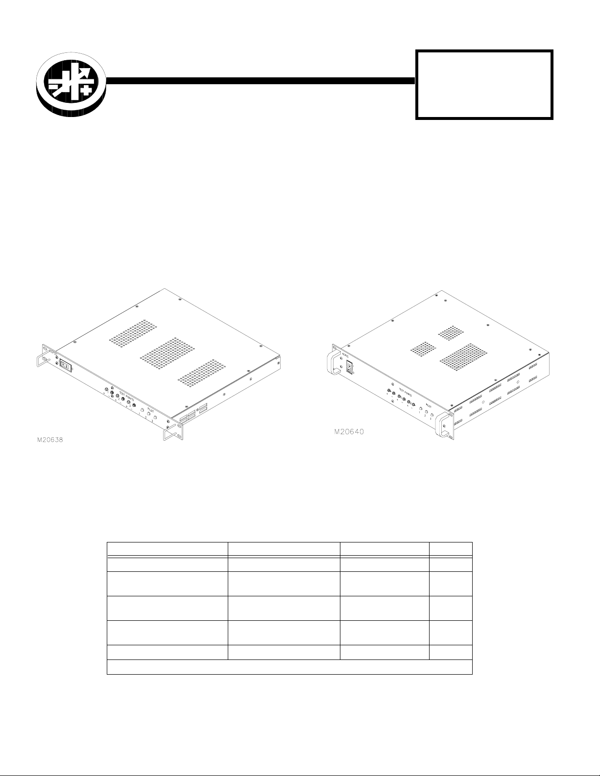
The Kepco RA 75 (Figure 1) and RA 76 (Figure 2) Rack Adapters are specifically designed for the installation of Kepco
FAW Series Power Supplies into 19-inch EIA standard equipment racks. Each Rack Adapter accommodates from one to
three FAW power supplies. The RA 75 Rack Adapter accommodates FAW 50W and 100W models; it occupies 1U, 1.75
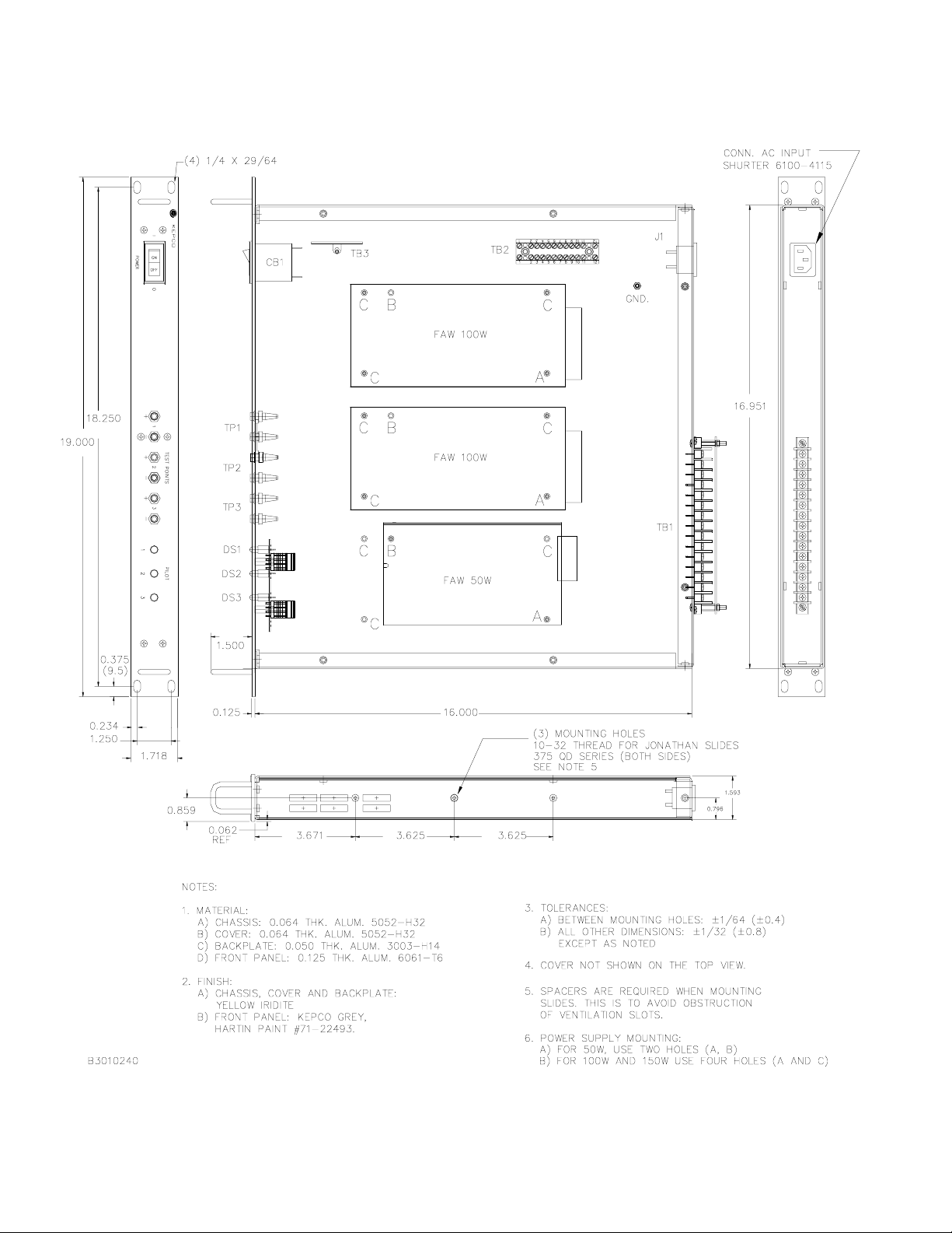
inches (44.5 mm) of vertical space in the standard 19 inch (482.6 mm) equipment rack, and has a maximum depth protrusion of 16.0 inches (406.4mm) as measured from the mounting surface of the front panel (see outline drawing, Figure 7).
The RA 76 Rack Adapter is identical, except that it occupies 2U, 3.5 inches (89 mm) of vertical space to accomodate FAW
150W as well as 50W and 100W models (see outline drawing, Figure 8). Table 1 lists equipment supplied.
FIGURE 1. RA 75 RACK ADAPTER FIGURE 2. RA 76 RACK ADAPTER
TABLE 1. EQUIPMENT SUPPLIED WITH RA 75 AND RA 76 RACK ADAPTER
DESCRIPTION FUNCTION KEPCO PART NO. QTY
Line Cord Connect A-C input power 118-0647 1
Multi terminal Jumper Strip
Two-terminal Sense Link
Resistor
Screw (4-40 x 3/8, ST, FLSO) Mount FAW power supplies 101-0237 15
* Quantity of 0.1 means 1/10 of 110-terminal Jumper Strip, equivalent to 12 terminals. Cut as needed.
KEPCO, INC. " 131-38 SANFORD AVENUE " FLUSHING, NY. 11352 U.S.A. " TEL (718) 461-7000 " FAX (718) 767-1102
http://www.kepcopower.com " email: hq@kepcopower.com
©2003, KEPCO, INC
Data subject to change without notice 228-1439 REV 1
Connect a-c power distribution (TB2) terminals
Connect sense and output terminals (TB1)
Limit current through CB1 indicator (see Fig. 6)
172-0394 0.1*
172-0300 6
115-1127 1
1
Page 2
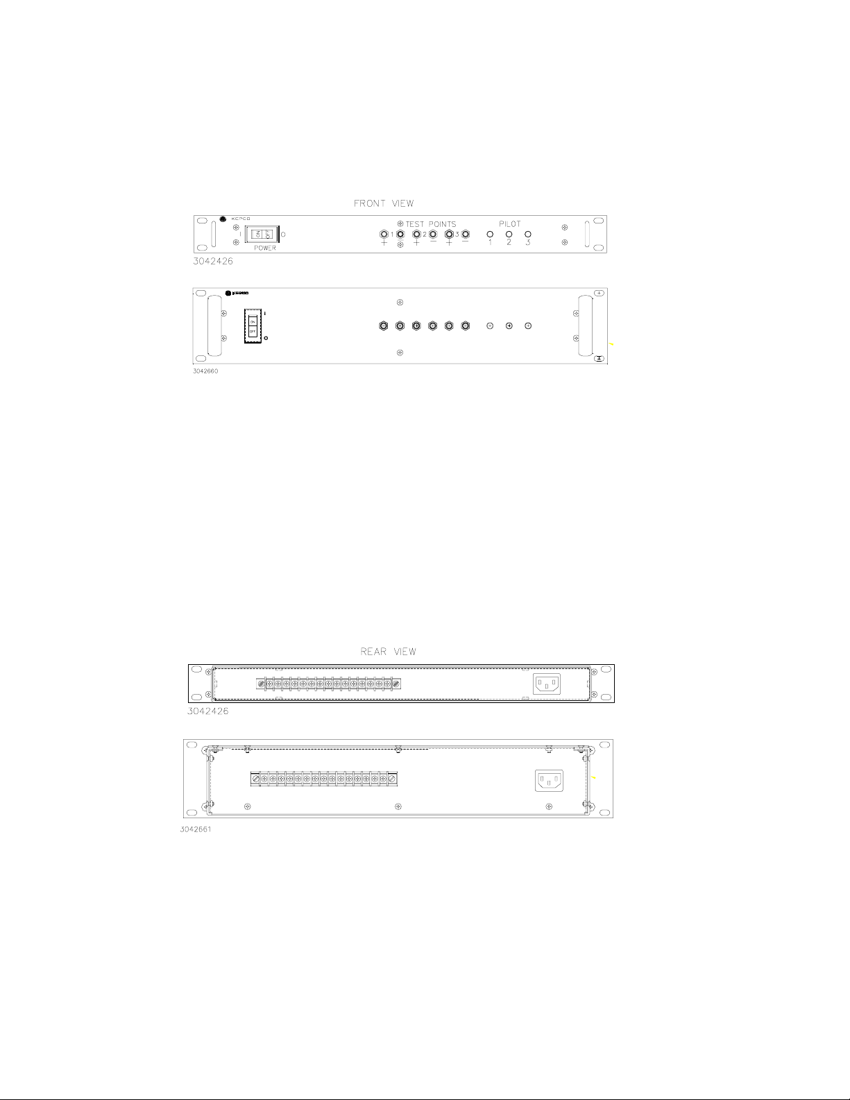
The front panel (Figure 3) is equipped with a 7.5A Input power circuit breaker that can be used to enable input power
to the FAW power supplies. Three front panel pilot lights can be wired to indicate whether the associated FAW power
supply is on. Front panel Test Points (+ and –) can also be wired so that the DC output voltages are accessible for
monitoring from the front panel.
RA 75
RA 76
POWER
TEST POINTS
+
−
3
21
+
+
−
PILOT
−
32
1
FIGURE 3. FRONT PANEL
The rear panel (Figure 4) includes a 15-terminal terminal block that can be used to make the FAW power supply outputs accessible and an a-c inlet connector. A separate 115V a-c line cord is included with the rack adapter.
RA 75
2
RA 76
FIGURE 4. REAR PANEL
228-1439 REV 1 6/20/03
Page 3
1. INSTALLATION
The Rack Adapter is equipped with handles; while installation is proceeding, the Rack Adapter must be supported
from below until it has been secured. The Rack Adapter can also be fitted with optional slides (see Figure 7).
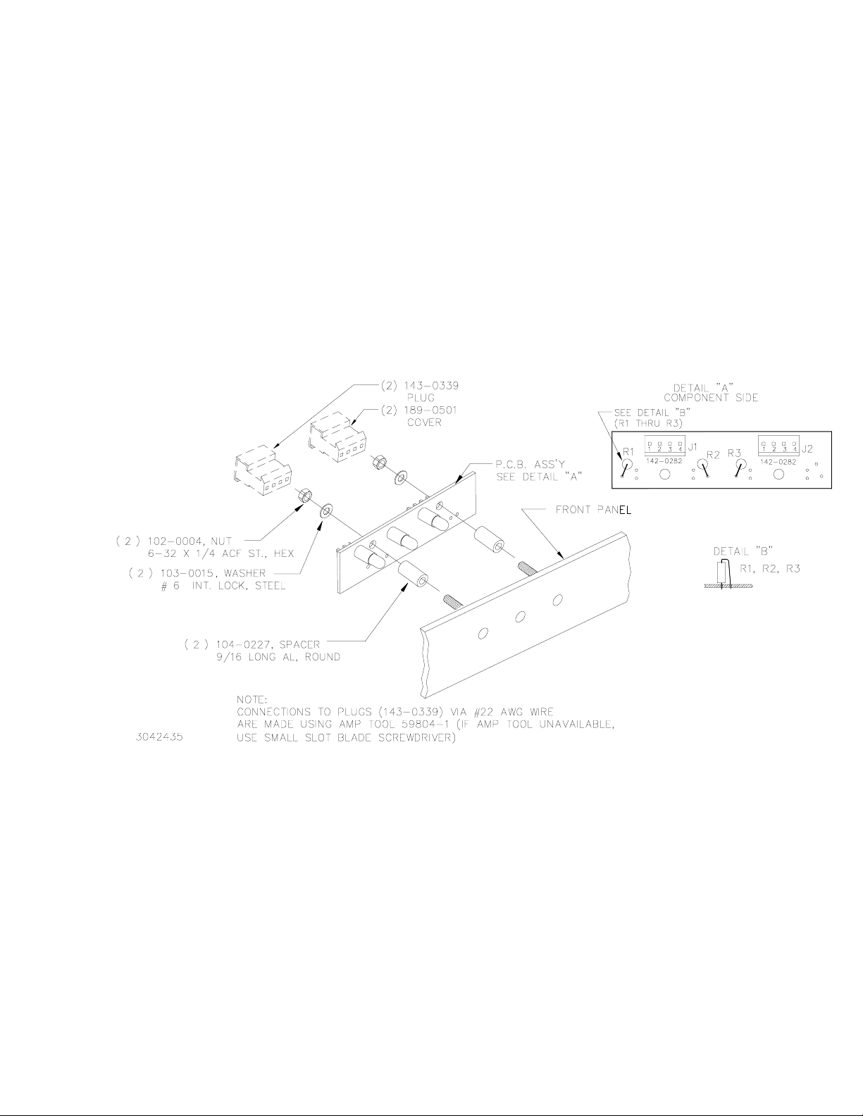
1. To activate the front panel pilot lights, the pilot light resistors must be configured to match the FAW output voltage prior to installing the power supplies. The front panel must be partially disassembled to facilitate the insertion of resistors matched to the associated power supply output voltage. Figure 6 illustrates the schematic.
Figure 5 illustrates component location. Proceed as follows:
a. Remove the top cover of the rack adapter by removing screws from the top (six for RA 75 and nine for RA
76) and one from the top center of the front panel above Test Point 1 (–).
b. Separate the front panel from the chassis by removing 5 screws from the front panel, then disassemble
the PCB assembly (see Figure 5) by removing two 6-32 X 1/4 ACF. ST. nuts (P/N 102-0004), associated
washers (P/N 103-0015) and spacers (P/N 104-0227).
FIGURE 5. FRONT PANEL DISASSEMBLY FOR INSERTION OF PILOT LIGHT RESISTORS
6/20/03 228-1439 REV 1
3
Page 4

c. Calculate the value (in ohms) of resistors A1R1 through A1R3, with respect to the power supply voltage (Vn)
and the operating characteristics of the LED (DS1 through DS3). Refer to Table 2 for resistor values and
Kepco part numbers associated with standard Kepco power supply output voltages.
where V
where V
where I
The following is an example for a resistor value associated with a 5 volt power supply:
resistor value (in ohms) Rn =
Calculate the power rating (in watts) as follows:
2 I
d. Position and solder resistor in place (see Figure 5).
e. Reassemble PCB assembly (see Figure 5) and reattach front panel to chassis using five screws.
= voltage across resistor/LED network (power supply output voltage)
n
= forward voltage across LED (approximately 2V)
F
= forward current across LED (approximately 20mA)
F
VnVF!
------------------
I
F
VnV
F
* use nearest larger standard size (1/4 or 1/2 Watt).
TABLE 2. RA 75/RA 76 RACK ADAPTER LEDS, RESISTOR SELECTION
!()×× 220mA 5V 2V!()××" 0.12W
F
OUTPUT VOLTAGE RESISTOR KEPCO P/N
5V 150Ω, 10%, 1/2W 115-0543
12V 560Ω, 5%, 1/2W 115-0888
5V 2V!
-------------------- 150 ohms
""
20mA
"
*
15V 750Ω, 5%, 1W 115-2438
24V 1.1KΩ, 5%, 1W 115-0545
28V 1.5KΩ, 10%, 1W 115-0664
48V 2.7KΩ, 10%, 2W 115-2465
2. Install the FAW power supplies in the Rack Adapter (see Figure 7) using four 4-40 x 3/8 ST. FLSO screws (supplied).
3. Wire the Rack Adapter as needed. Schematic Diagram Figure 6 is provided as a guide showing a typical installation of three FAW power supplies. Be sure to connect resistor RS1 (supplied).
4. Replace top cover and secure with screws removed during disassembly.
5. Install the line cord (supplied) at connector J1 at the rear panel.
6. Install the unit in the rack and secure using suitable mounting hardware (not supplied).
4
228-1439 REV 1 6/20/03
Page 5

FIGURE 6. SCHEMATIC DIAGRAM
6/20/03 228-1439 REV 1
5
Page 6
.
FIGURE 7. RA 75 RACK ADAPTER OUTLINE DRAWING
6
228-1439 REV 1 6/20/03
Page 7

POWER
FIGURE 8. RA 76 RACK ADAPTER OUTLINE DRAWING
6/20/03 228-1439 REV 1
7
Page 8

KEPCO
REPLACEMENT PARTS LIST
RA 75, RA 76 CHASSIS ASSEMBLY CODE: 1306153
REFERENCE
DESIGNATOR
A1J1, A1J2 2 ASSY., PLUG, PCB MOUNT
CB1 1 CIRCUIT BREAKER, (FULLY MAG-
DS1, DS2, DS3 3 DEVICE, SIGNALING, , LED-GN
J1 1 CONNECTOR, POWER INLET,
P1, P2 2 PLUG, SOCKET, CABLE CONNEC-
RS1 1 RES., FIX., CARBON FILM,
TB1 1 TERMINAL BLOCK,
TB2 1 TERMINAL BLOCK, COMPACT,
TB3 1 TERMINAL STRIP, 4 LUGS KEYSTONE ELECTR
QTY. DESCRIPTION
(STRAIGHT PINS), 4 PINS
NETIC), 1POLE 125VAC 7.5A
DIFFUSED LENS, VF=2.7V
3 PINS
TOR, 4 PINS
33 KOHM , 1/2W, 5%
15 TERMINALS, 20A/TERM.
12 POLE
MFRS. NAME & PART NO.
(SEE BOTTOM NOTE)
AMP INC
640445-4
CARLING TECHNOL
MF1-B-34-475-1-BB2-B-C
DIALIGHT CORP.
521-9250
SCHURTER
6100-4115
AMP INC.
640428-4
KOA/SPEER
CF1/2 333 J T52A
MAGNUM (USD)
A2193-15-07-MP
WIELAND
29.401.1253 *
818
KEPCO
PART NO.
142-0282 1
127-0383 1
153-0094 1
143-0616 1
143-0339 1
115-1127 1
167-1023 1
167-0995 1
167-0554 1
REC. SPARE
PART Q TY.
TP1(+), TP2(+),
TP3(+)
TP1(-), TP2(-),
TP3(-)
3 TEST POINT, JACK-RED KEYSTONE ELECTR
6025
3 TEST POINT, JACK-BK KEYSTONE ELECTR
6026
173-0001 1
173-0002 1
NOTE: REPLACEMENT PARTS MAY BE ORDERED FROM KEPCO, INC. ORDERS SHOULD INCLUDE KEPCO PART NUMBER AND DESCRIPTION.
PLEASE NOTE: THE MANUFACTURER'S NAME AND PART NUMBER LISTED FOR EACH ITEM ON REPLACEMENT PARTS LISTS REPRESENTS
AT LEAST ONE SOURCE FOR THAT ITEM AND IS LISTED SOLELY FOR THE CONVENIENCE OF KEPCO EQUIPMENT OWNERS IN OBTAINING
REPLACEMENT PARTS LOCALLY. WE RESERVE THE RIGHT TO USE EQUIVALENT ITEMS FROM ALTERNATE SOURCES. KEPCO, INC.
8
RA75/RA76 6/20/03
 Loading...