

Page 1
INSTRUCTION MANUAL
RA 60 SERIES
RACK ADAPTER
RA 60, RA 62, AND RA 63
KEPCO INC.
An ISO 9001 Company.
RA 60 SERIES
RACK ADAPTER
ORDER NO. REV. NO.
IMPORTANT NOTES:
1) This manual is valid for the following Model and associated serial numbers:
MODEL SERIAL NO. REV. NO.
2) A Change Page may be included at the end of the manual. All applicable changes and
revision number changes are documented with reference to the equipment serial numbers. Before using this Instruction Manual, check your equipment serial number to identify
your model. If in doubt, contact your nearest Kepco Representative, or the Kepco Documentation Office in New York, (718) 461-7000, requesting the correct revision for your
particular model and serial number.
3) The contents of this manual are protected by copyright. Reproduction of any part can be
made only with the specific written permission of Kepco, Inc.
Data subject to change without notice.
MODEL
©2010, KEPCO, INC
P/N 243-0909R2
KEPCO, INC. O 131-38 SANFORD AVENUE O FLUSHING, NY. 11355 U.S.A. O TEL (718) 461-7000 O FAX (718) 767-1102
email: hq@kepcopower.com
O World Wide Web: http://www.kepcopower.com
KEPCO®
THE POWER SUPPLIER™
Page 2

Declaration of Conformity
Application of Council directives:
Standard to which Conformity is declared:
EN60950-1:1992 +A1: 1993 + A2 : 1993 (Safety of information technology equipment,
Manufacturer's Name and Address:
Importer's Name and Address:
Type of Equipment:
Model No.:
73/23/EEC (LVD)
93/68/EEC (CE mark)
including electrical business equipment)
KEPCO INC.
131-38 SANFORD AVENUE
FLUSHING, N.Y. 11355 USA
Y
P
O
C
E
V
I
T
A
T
N
E
S
E
R
P
E
R
Rack Adapter
[PRODUCT MODEL NUMBER]
Year of Manufacture:
I, the undersigned, declare that the product specified above, when used in conjunction with the conditions of
conformance set forth in the product instruction manual, complies with the requirements of the Low Voltage
Directive 73/23/EEC, which forms the basis for application of the CE Mark to this product.
Place: KEPCO Inc.
131-38 Sanford Ave.
Flushing, N.Y.11355 USA
Saul Kupferberg
(Full Name)
Date:
A 228-1360 RA (60950) 090910
VP OF SALES
(position)
Page 3

Conditions of Conformance
Rack Adapter products (EN60950)
When this product is used in applications governed by the requirements of the EEC, the following restrictions and conditions apply:
1. For European applications, requiring compliance to the Low Voltage Directive, 73/23/EEC, this Rack
Adapter is considered a component, designed for “building in”. Because it is incomplete in construction, the end product enclosure must provide for compliance to any remaining electrical safety requirements and act as a fire enclosure. (EN60950, CL.2.1, 2.7, 3.3, 4.3 and 4.4.5).
2. This Rack Adapter is designed for stationary installation, with mains power applied via a detachable
power supply cord or via direct wiring to a source power terminal block.
3. This Rack Adapter, when properly installed, is considered a Class 1 (earthed) product, and as such
depends upon proper connection to protective earth for safety from electric shock. (EN60950 Cl. 2.5)
4. This product is intended for use as part of equipment meant for an Information Technology Equipment
environment. It is designed to operate from single phase, three wire TN power systems. This equipment must be installed within a suitably wired equipment rack, utilizing a three wire (grounded) mains
connection. See wiring section of this manual for complete electrical wiring instructions.
5. When fitted with the appropriate power supplies, this product may have secondary output circuits that
are considered hazardous, and which exceed 240 VA at a potential of 2V or more.
6. The output wiring terminals of this power supply have not been evaluated for field wiring and, therefore, must be properly configured by the end product manufacturer prior to use.
7. For complete circuit protection of the end product, as well as the building wiring, it is required that a primary circuit protection device be fitted to the branch circuit wiring. (EN60950 Cl. 2.5).
8. When installed with other components and/or power supplies, hazardous voltages may be present
within the equipment during normal operation. All operator adjustments are made via externally accessible switches, controls and signal lines as specified within the individual power supply operating
instructions. There are no user or operator serviceable parts within this product enclosure. Refer all
servicing to qualified and trained Kepco service technicians.
228-1363 COND/CONFORM 090910 B
Page 4
SAFETY INSTRUCTIONS
1. Installation, Operation and Service Precautions
This product is designed for use in accordance with EN 60950 and UL 1950 for Installation Category 2,
Pollution Degree 2. Hazardous voltages are present within this product during normal operation. The product should never be operated with the cover removed unless equivalent protection of the operator from
accidental contact with hazardous internal voltages is provided
!
!
!
There are no operator serviceable parts or adjustments within the product enclosure.
Refer all servicing to trained service technician.
Source power must be removed from the product prior to performing any servicing.
This product is factory-wired for the nominal a-c mains voltage indicated on the rating nameplate located adjacent to the source power connection on the product's rear
panel.
2. Grounding
This product is a Class 1 device which utilizes protective earthing to ensure operator safety.
The PROTECTIVE EARTHING CONDUCTOR TERMINAL must be properly con-
!
nected prior to application of source power to the product (see instructions on installation herein) in order to ensure safety from electric shock.
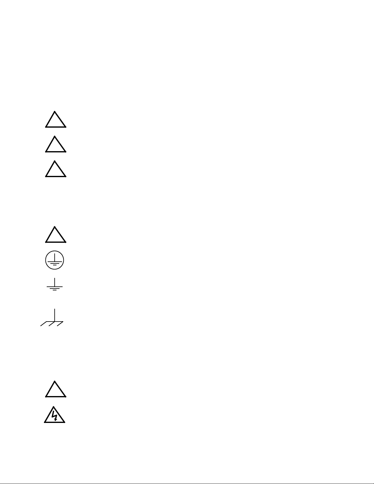
PROTECTIVE EARTHING CONDUCTOR TERMINAL - This symbol indicates the
point on the product to which the protective earthing conductor must be attached.
EARTH (GROUND) TERMINAL - This symbol is used to indicate a point which is
connected to the PROTECTIVE EARTHING TERMINAL. The component installer/
assembler must ensure that this point is connected to the PROTECTIVE EARTHING TERMINAL.
CHASSIS TERMINAL -This symbol indicates frame (chassis) connection, which is
supplied as a point of convenience for performance purposes (see instructions on
grounding herein). This is not to be confused with the protective earthing point, and
may not be used in place of it.
3. Electric Shock Hazards
This product outputs hazardous voltage and energy levels as a function of normal operation. Operators
must be trained in its use and exercise caution as well as common sense during use to prevent accidental
shock.
This symbol appears adjacent to any external terminals at which hazardous voltage
!
C 090910
levels as high as 500V d-c may exist in the course of normal or single fault conditions.
This symbol appears adjacent to any external terminals at which hazardous voltage
levels in excess of 500V d-c may exist in the course of normal or single fault conditions.
Page 5

TABLE OF CONTENTS
SECTION PAGE
SECTION 1 - INTRODUCTION
1.1 Scope of Manual ..................................................................................................................................... 1
1.2 General Description................................................................................................................................. 1
1.3 Options .................................................................................................................................................... 1
1.4 Accessories ............................................................................................................................................. 4
SECTION 2 - INSTALLATION
2.1 Unpacking and Inspection ....................................................................................................................... 1
2.2 Rack Adapter Keying Instructions ........................................................................................................... 1
2.3 Terminations............................................................................................................................................ 2
2.4 Cooling .................................................................................................................................................... 2
2.5 Installation ............................................................................................................................................... 2
2.5.1 Mounting Ear Installation ................................................................................................................... 4
2.6 Wiring Instructions................................................................................................................................... 5
2.6.1 Safety Grounding............................................................................................................................... 5
2.6.2 Source Power Connections ............................................................................................................... 6
2.6.3 Source Power Configurations............................................................................................................ 6
2.6.3.1 A-C Source Power, Single Phase ................................................................................................ 7
2.6.3.2 A-C Source Power, Three Phase................................................................................................. 7
2.6.3.3 D-C Source Power....................................................................................................................... 8
2.6.4 Control Signal Connections ............................................................................................................... 8
2.6.4.1 Sense Connections...................................................................................................................... 8
2.6.5 Output Load Connections.................................................................................................................. 9
2.6.5.1 Parallel/Redundant Operation...................................................................................................... 9
2.6.5.2 Series/Independent Operation ..................................................................................................... 9
2.7 Shipping .................................................................................................................................................. 9
RA 60 SERIES 090910 i
Page 6

LIST OF FIGURES
FIGURE TITLE PAGE
1-1 Series RA 60 Rack Adapter ....................................................................................................................... 1-iv
1-2 Mechanical Outline Drawing, Series RA 60 Rack Adapter......................................................................... 1-2
2-1 Key Pin Location ........................................................................................................................................ 2-1
2-2 Rear Panel Connections ............................................................................................................................ 2-2
2-3 Mounting Dimensions................................................................................................................................. 2-3
2-4 Set-back Dimensions ................................................................................................................................. 2-4
2-5 Mounting Ear Installation............................................................................................................................ 2-5
2-6 Single Phase A-C/D-C Source Power Wiring............................................................................................. 2-7
2-7 Three Phase Delta A-C Source Power Wiring ........................................................................................... 2-7
2-8 Three Phase Wye A-C Source Power Wiring............................................................................................. 2-8
ii RA 60 SERIES 090910
Page 7

LIST OF TABLES
TABLE TITLE PAGE
1-1 Rack Adapter Options .................................................................................................................................1-4
1-2 Accessories .................................................................................................................................................1-4
2-1 Equipment Supplied ....................................................................................................................................2-1
RA 60 SERIES 090910 iii
Page 8
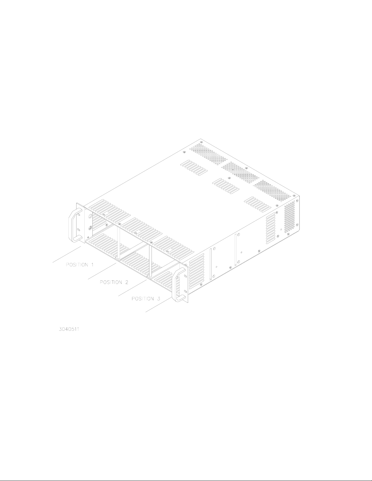
FIGURE 1-1. SERIES RA 60 RACK ADAPTER
iv RA60 SERIES090910
Page 9

SECTION 1 - INTRODUCTION FIGURE 1-1.
1.1 SCOPE OF MANUAL
This manual contains instructions for the installation and operation of RA 60 Series plug-in rack
adapters (Figure 1-1), including RA 60, RA 62 and RA 63, used with HSP Series power supplies, manufactured by Kepco, Inc., Flushing, New York, U.S.A.
1.2 GENERAL DESCRIPTION
Kepco Series RA 60 rack adapters are specifically designed for the installation of Kepco HSP
Series Power Supplies into 19-inch, 23-inch and 24-inch EIA standard equipment racks. Each
rack adapter accommodates from one to three HSP power supplies. An internal plate assembly
mounts connectors which interface directly with the power and signal connectors of HSP series
power supplies, permitting pluggable insertion and extraction, while a separate external rear
panel contains the fixed power and signal connections. Separate source power, signal, and load
terminations are provided for each of the three power supply mounting positions. Internal power
output configurations differ for the three models as follows:
• RA 60 Output power connections for all three positions are internally connected for
parallel/redundant applications.
• RA 62 Output power connections for positions 1 and 2 are internally paralleled,
position 3 is independent from the other two.
• RA 63 Output power connections not connected internally, all three positions are
External dimensions and mounting provisions are identical for all Series RA 60 Rack Adapter
models All mechanical and electrical specifications are contained in the outline drawing: Figure
1-2.
Each rack adapter occupies 5.22 inches (132.5 mm) of vertical space and has a maximum
depth protrusion of 21 inches measured from the mounting surface of the “ear” brackets. Mounting positions are provided for flush mount as well as ¼ setback and ½ setback (notched mounting ears required). All rack adapters are shipped with mounting ears for flush mounting in EIA
19-inch equipment racks. The rack adapters can be fitted with optional blank filler panels in both
1/3 and 2/3 dimensions if the full complement of three power supplies is not utilized.
1.3 OPTIONS
Series RA 60 Rack Adapters are available for 19-inch, 23-inch, and 24-inch wide racks. Table 11 below describes the model options available with Series RA 60 rack adapters.
independent of each other
RA60 SERIES090910 1-1
Page 10

FIGURE 1-2. MECHANICAL OUTLINE DRAWING, SERIES RA 60 RACK ADAPTER (SHEET 1 OF 2)
1-2 RA60 SERIES090910
Page 11

FIGURE 1-2. MECHANICAL OUTLINE DRAWING, SERIES RA 60 RACK ADAPTER (SHEET 2 OF 2)
RA60 SERIES090910 1-3
Page 12

TABLE 1-1. RACK ADAPTER OPTIONS
MODEL DESCRIPTION
RA 60, RA 62, RA 63 Accommodates up to three HSP Power Supplies in a 19-inch rack. Used for
hot-swap independent, series or parallel/redundant applications where
HSPs are plugged in to the rack adapter and can be easily removed and
inserted without affecting system operation.
RA 60-23E, RA 62-23E, RA 63-23E Same as RA 60, RA 62, RA 63 except mounting ears are wider to accom-
modate a 23-inch rack.
RA 60-24E, RA 62-24E, RA 63-24E Same as RA 60, RA 62, RA 63 except mounting ears are wider to accom-
modate a 24-inch rack.
1.4 ACCESSORIES
Accessories for HSP Power Supplies are listed in Table 1-2.
TABLE 1-2. ACCESSORIES
ACCESSORY PART NUMBER USE
128-1714
MOUNTING
BRACKETS
(NOTCHED)
MOUNTING
BRACKETS
(UNNOTCHED)
CONNECTORS
FILLER
PAN ELS
ALUMINUM FEET 158-0004
SCREW 101-0215 Used to attach aluminum feet to rack adapter.
SLIDE KIT
(preferred)
SLIDE KIT Kit 219-0442
SAFETY COVER, AC 137-0136 Cover source power connections.
SAFETY COVER, DC 137-0135 Cover output power connections.
SCREW 101-0456 Pan head, phillips, self-forming, 6-32 x 1/4 used to attach safety covers.
SUPPORT BRACKET 128-1775
128-1736
128-1827
128-1631 Standard mounting ear for 19-inch rack applications.
128-1776
142-0422 I/O connector mating plug.
108-0294 I/O connector backshell.
RFP 60-1 Covers 1/3 of front panel.
RFP 60-2 Covers 2/3 of front panel.
Kit 219-0433
Used to mount RA 60, RA 62, or RA 63 in 19-inch rack using “set back” position (see
Figure 2-4).
Used to mount RA 60, RA 62, or RA 63 in 23-inch rack using “set back” position (see
Figure 2-4).
Used to mount RA 60, RA 62, or RA 63 in 24-inch rack for both flush and “set back”
positions (see Figure 2-4).
Used for standard (flush) mounting of RA 60, RA 62, or RA 63 in 23-inch rack (see
Figure 2-4).
Aluminum feet attach to bottom of rack adapter (set of four).
Slide Kit includes two slides, mounting brackets and attaching hardware; allows rack
adapter to be pulled out of rack. Recommended for 18-20 inch setback to intermediate cabinet rail.
Slide Kit includes two slides, extended mounting brackets and attaching hardware;
allows rack adapter to be pulled out of rack. Recommended for 22-26 inch setback
to intermediate or rear cabinet rail if Kit 219-0433 can not be used.
Pair required. Used to provide side support for rack adapter. Requires rear rail at 1813/16 in. setback.
1-4 RA60 SERIES090910
Page 13

SECTION 2 - INSTALLATION
2.1 UNPACKING AND INSPECTION
This instrument has been thoroughly inspected and tested prior to packing and is ready for
operation. After careful unpacking, inspect for shipping damage before attempting to operate. If
any indication of damage is found, file an immediate claim with the responsible transport service. See Table 2-1 for a list of equipment supplied.
TABLE 2-1. EQUIPMENT SUPPLIED
ITEM QUANTITY PART NUMBER
Rack Adapter 1 RA 60, RA 62, or RA 63
I/O Connector (Mating) 3 142-0422
Instruction Manual 1 243-0848
Split Lockwasher * 6 103-0005
Hex Nut, 5/16-18 * 6 102-0105
* Mounting hardware is assembled to output studs.
2.2 RACK ADAPTER KEYING INSTRUCTIONS
All RA 60 Series rack adapters incorporate a keying mechanism to prevent accidental insertion
of the incorrect model HSP power supply into any position. The HSP power supplies are keyed
by voltage at the factory. The keying mechanism will prevent engagement of any of the HSP
power supply's connectors with those on the rack adapter's intermediate plate unless the key
and keyway align. The user can configure each power supply position of the rack adapters for
the desired voltage in the desired position; the factory default keying is for the 5-volt HSP module (see Figure 2-1).
The key pins (Kepco P/N 108-0079) used for module keying are located on the intermediate
plate (see Figure 2-1) and are accessed through the front of the rack adapter. To alter the keying
of any position, simply unscrew the key pin from the intermediate plate using a ¼" nutdriver or
deep socket, reposition key pin at new location and retighten. HSP module keying is identified in
Figure 2-1 and in the HSP operator's manual. DO NOT ALTER THE KEYING AT THE POWER
SUPPLY!
FIGURE 2-1. KEY PIN LOCATION
RA60 SERIES 090910 2-1
Page 14

2.3 TERMINATIONS
All input, output and control terminations are located on the rear panel of the rack adapter (see
Figure 2-2). Other than module keying (Para.2.2), no adjustments or alignments are required.
FIGURE 2-2. REAR PANEL CONNECTIONS
2.4 COOLING
The HSP power supplies mounted within the rack adapter are maintained within their operating
temperature range by means of internal cooling fans. ALL INLET AND EXHAUST OPENINGS
AROUND THE RACK ADAPTER CASE MUST BE KEPT CLEAR OF OBSTRUCTION TO
ENSURE PROPER AIR ENTRY AND EXHAUST. Care must be taken that the ambient temperature, which is the temperature of the air immediately surrounding the rack adapter, does not
rise above the specified limits for the operating load conditions of the installed HSP power supplies. Kepco recommends providing additional space above and below the rack adapter where
possible when the rack adapter is fully populated.
2.5 INSTALLATION (Refer to “Mechanical Outline Drawing,” Figure 1-2.
RA 60 Series rack adapters are designed for rack-mounted applications. The rack adapter will
mount directly to EIA standard 19" racks; optional mounting ears are available to provide for
2-2 RA60 SERIES 090910
Page 15

mounting to EIA standard 23" and 24" racks (see Figure 2-3 and Table 1-2). Other fixed mounting applications are possible; consult factory for details.
FIGURE 2-3. MOUNTING DIMENSIONS
(a) When used in fixed rack-mounted applications, the rack adapter is attached to the rack via
the two mounting ears; two screws are required per mounting ear for proper support.
RA60 SERIES 090910 2-3
Page 16

(b) The rack adapter can be attached to the rack using chassis slides; the rack adapter sides are
predrilled for 18" (457.2mm) chassis slides (see Table 1-2).
(c) For applications which require less depth protrusion of the rack adapter within the rack, the
rack adapters provide two “set-back” positions for use with optional notched mounting ears
(see Tables 1-1 and 1-2); see Figure 2-4 for set-back dimensions.
For all installations provide adequate clearance around air inlet and exhaust locations and
ensure that the temperature immediately surrounding the unit, and especially near the air inlets,
does not exceed the maximum specified ambient temperature for the operating conditions of the
installed power supplies.
CAUTION
WHEREVER POSSIBLE RACK ADAPTER SHOULD BE MOUNTED BEFORE INSTALLING
POWER SUPPLIES TO AVOID DISTORTION OF THE RACK ADAPTER (INSTALL POPULATED RACK ADAPTER ONLY IF BOTTOM OF RACK ADAPTER IS FULLY SUPPORTED).
FAILURE TO OBSERVE THIS CAUTION MAY RESULT IN MISALIGNMENT OF THE POWER
SUPPLIES WITH THE RACK ADAPTER.
FIGURE 2-4. SET-BACK DIMENSIONS
2.5.1 MOUNTING EAR INSTALLATION
If mounting ears are removed, or optional mounting ears are purchased to allow installation in a
different size rack, install each standard (unnotched) mounting ear with spacer (part number
128-1716) between the mounting ear and the inside surface of the rack adapter chassis (see
2-4 RA60 SERIES 090910
Page 17

Figure 2-5). Attach mounting ear to chassis using the two screws and two lockwashers provided.
Installation of the notched mounting ears is similar to the above procedure, except the notched
flange is first inserted in the slot on the rack adapter chassis, then rotated 90 degrees while the
spacer is inserted between the mounting ear flange and the inside surface of the rack adapter
chassis (see Figure 2-5).
FIGURE 2-5. MOUNTING EAR INSTALLATION
2.6 WIRING INSTRUCTIONS
Interconnections between an a-c power source and a stabilized power supply, and between the
power supply and its load are as critical as the interface between other types of electronic equipment. If optimum performance is expected, certain rules for the interconnection of source, power
supply and load must be observed by the user. These rules are described in detail in the following paragraphs and in the operating instructions for HSP Series power supplies.
2.6.1 SAFETY GROUNDING
Local, national and international safety rules dictate the grounding of the metal cover and case
of any instrument connected to the a-c power source, when such grounding is an intrinsic part of
the safety aspect of the instrument. The instructions below suggest wiring methods which comply with these safety requirements; however, in the event that the specific installation for the
power system involves differences with the recommended wiring, it is the customer's responsibility to ensure that all applicable electric codes for safety grounding requirements are met.
RA60 SERIES 090910 2-5
Page 18

2.6.2 SOURCE POWER CONNECTIONS
When used in conjunction with Kepco HSP series power supplies, these rack adapters can be
operated from either single-phase or three-phase a-c source power without adjustment or modification. Voltage and frequency limits are determined by the source power rating of the HSP
power supplies. Operation from d-c power is also available; please contact factory for limitations
imposed when using d-c source power.
The rear panel of RA 60 Series rack adapters (Figure 2-2) includes seven terminal blocks to
allow for connection of single-phase a-c, three-phase a-c (4-wire or 5-wire) and d-c input power.
These terminal blocks are labeled L1, N1, L2, N2, L3, N3, and G. Wires must be sized according
to expected current. Each terminal block will accommodate up to #6 AWG (16mm²) or equivalent conductor size; torque to 15 lb-in (1.5 N•M) maximum. Their functions are:
• Terminal G is the safety ground connection for the rack adapter. It is connected to the rack
adapter chassis as well as to the safety ground terminal of the source power connector of
each of the three power supply mounting positions. Regardless of the type of source power
provided, Terminal G must be connected to safety ground in order to ensure proper grounding of the HSP power supplies when installed. The conductor used to connect Terminal G to
safety ground must be sized to support the total fault current of all of the power supplies
installed in the rack adapter; for HSP series power supplies, the ground fault current rating
is 20 amperes per power supply. Consult local electric codes for the proper wire size to
carry the required fault current.
• Terminal pairs L1/N1, L2/N2, L3/N3 are connected to the high-side and low-side contacts
of the source power connectors for each of the three power supply mounting positions (1, 2
and 3) of the rack adapter (see Figure 2-2). Each terminal pair (Lx/Nx) is isolated from the
remaining two pairs, facilitating redundant source power connections if desired. The conductor used to connect terminals Lx and Nx to source power must be sized for the 16
ampere maximum source current drawn by HSP Series power supplies; Kepco recommends #14 AWG (2.5mm²) or equivalent minimum conductor size to support this current.
2.6.3 SOURCE POWER CONFIGURATIONS
The following standard wiring configurations are recommended by Kepco as being compliant
with national and international safety standards. It is the user's responsibility to ensure that all
applicable local electric codes are met. The minimum and maximum limits for source power voltage are defined in HSP series power supply specifications.
UNDER NO CIRCUMSTANCES SHOULD THE STEADY-STATE SOURCE VOLTAGE
APPLIED ACROSS ANY Lx/Nx PAIR EXCEED 277V rms!
CAUTION
2-6 RA60 SERIES 090910
Page 19

2.6.3.1 A-C SOURCE POWER, SINGLE PHASE
For single-phase a-c source power, connect Terminal G of the rack adapter to source power
safety ground; then connect a separate wire pair from the power source to each Lx/Nx terminal
block pair to be populated by an HSP power supply (see Figure 2-6).
FIGURE 2-6. SINGLE PHASE A-C/D-C SOURCE POWER WIRING
If desired, a single wire pair can be run from the power source to any Lx/Nx pair, with jumpers
connecting the remaining Lx/Nx pairs to the first pair; however, the wires must be adequately
rated to support the total current being delivered through them. For the example shown in Figure 2-6, the jumper wires are sized for 16 amps, but the source wires must be sized for 3 times
16 amps, or 48 amps.
2.6.3.2 A-C SOURCE POWER, THREE PHASE
Three-phase a-c source power from either delta- or wye-configuration power sources can be
used. When using wye-configuration power, the user should configure the power system so as
to balance the load drawn from each phase to minimize the current flow in the source power
neutral wire whenever possible. When possible, the user should wire the rack adapter in accordance with the instructions for delta power in order to take advantage of the lower input current
requirements. Regardless of the source power configuration, Terminal G of the rack adapter
must be connected to safety ground.
• Delta Power - Connect a separate wire pair from each Lx/Nx pair on the rack adapter
across successive line terminals of the source power (e.g., A-B, B-C, C-A) (see Figure 2-7).
FIGURE 2-7. THREE PHASE DELTA A-C SOURCE POWER WIRING
RA60 SERIES 090910 2-7
Page 20

• Wye Power - Connect a separate wire pair from each Lx/Nx pair on the rack adapter to line
and neutral terminals of the power source, using successive line terminals (e.g., A-N, B-N,
C-N) (see Figure 2-8)
FIGURE 2-8. THREE PHASE WYE A-C SOURCE POWER WIRING
2.6.3.3 D-C SOURCE POWER
For d-c source power, wire the rack adapter in accordance with the instructions for single-phase
a-c power per Para. 2.6.3.1. Contact Kepco Applications Engineering for additional restrictions
imposed by d-c source power.
2.6.4 CONTROL SIGNAL CONNECTIONS
Access to the control signal (I/O) connector for each HSP power supply is provided via the three
37-pin D-subminiature connectors on the rear panel of the rack adapter (see Figure 2-2). Three
mating connectors (Kepco PN 142-0422) are provided in a plastic bag. These connectors are
simply extensions of the identical connectors located on the HSP power supplies. Consult the
HSP operator's manual for instructions on wiring and use of these control lines.
2.6.4.1 SENSE CONNECTIONS
The user MUST configure either local or remote sensing. Local sensing is accomplished by connecting +S (pin 37) of the I/O Connector to the + stud at the rear of the rack adapter, and –S (pin
19) of the I/O Connector to the – stud. Remote sensing is accomplished by connecting +S (pin
37) of the I/O Connector to the + terminal of the load, and –S (pin 19) of the I/O Connector to the
– terminal of the load. Refer to HSP Operator manual for instructions on wiring.
REGARDLESS OF OUTPUT CONFIGURATION, OUTPUT SENSE
LINES MUST BE PROPERLY CONNECTED FOR OPERATION
(REFER TO HSP OPERATOR'S MANUAL).
NOTE!
2-8 RA60 SERIES 090910
Page 21

2.6.5 OUTPUT LOAD CONNECTIONS
Load connections to the rack adapters are achieved via the stud pairs located on the rear panel
directly behind each mounting position (see Figure 2-2). Required hardware for attaching output
cables are assembled to the output studs. Wires must be sized according to expected current.
Wire size range is between 22 and 6 GA, depending on the ring lug; torque to 40 lb-in (45 N•M)
maximum. RA 60 rack adapters provide permanent interconnection of the three power supply
positions for parallel/redundant configuration. All three load connections must be used when the
3.3 volt and 5 volt modules are used. RA 62 and RA 63 rack adapters employ a modular bus bar
system to permit a variety of load configurations. The following sections describe the basic output bus bar configurations available with Series RA 60 rack adapters. Additional information
regarding these and other load interface requirements are contained in the HSP operator's manual.
2.6.5.1 PARALLEL/REDUNDANT OPERATION
RA 60 and RA 62 rack adapters provide permanently configured outputs for parallel/redundant
operation: all three positions for RA 60, positions 1 and 2 for RA 62. Load wiring is attached to
the rack adapter at the output studs. Although load wiring can be attached to any single position,
Kepco strongly recommends distributing the load interface evenly among the populated power
supply positions to minimize load sharing error; in no case should load current drawn from any
one terminal exceed 300 Amperes. Consult HSP operator's manual for additional information
regarding parallel/redundant load operation.
2.6.5.2 SERIES/INDEPENDENT OPERATION
RA 63 rack adapters can be used for either independent or series operation of HSP power supplies. For series operation, install a jumper cable from the negative bus bar of one independent
position to the positive bus bar of the adjacent independent position for as many positions as
required. Consult the HSP operator's manual for additional information regarding series operation. The RA 60 cannot be used for series operation except when connecting consecutive rack
adapters in series; contact Kepco Applications Engineering for additional information.
2.7 SHIPPING
Shipping of the rack adapter is recommended only after the HSP power supplies have been
removed from the rack adapter. Contact Kepco Applications Engineering if further assistance is
required.
RA60 SERIES 090910 2-9/(2-10 Blank)
Page 22

Page 23

You must register your product to comply with the terms of the warranty. Either fill out the form
below and mail or fax to Kepco, or for rapid on-line registration go to:
http://www.kepcopower.com/warranty.htm
PRODUCT PURCHASED:
Model Number)______________________________________
Serial Number_______________________________________
PURCHASE INFORMATION:
Date Purchased:_____________________________________
Date Received:______________________________________
REQUEST ADDITIONAL INFORMATION
# Send complete Catalog
# Have Sales Engineer Call
Contact via: # E-Mail # Telephone # Fax # S-mail
REGISTER TO:
Registered by:________________________________________
Company Name:______________________________________
Street: ______________________________________________
City:________________________________________________
State:_______________________________________________
Country:_____________________________________________
Zip:_________________________________________________
E-mail: ______________________________________________
FAX:____________________________________________
Phone: _________________________________________
WHAT INFLUENCED YOUR CHOICE OF THIS POWER SUPPLY?
# Previous Experience (which Kepco Models do you have?)
______________________________________________________
# Kepco Catalog or Brochure?__________________________
# Sales Representative?
______________________________________________________
______________________________________________________
# Magazines (which ones?)_____________________________
______________________________________________________
# Trade Shows (which ones?)___________________________
# Directory?__________________________________________
Kepco 5 Year Warranty
This is to certify that we, KEPCO, INC., (hereinafter called “Company”), Flushing, NY
11352 USA, warrants for a period of FIVE YEARS, this instrument known as:
MODEL: __________________________________________
SERIAL NO. _________________________________________
The Company’s products are warranted for a period of five years from date of delivery to
be free from defects in materials and workmanship and to conform to the specifications
furnished or approved by the Company. Liability under this warranty shall be limited to
the repair or replacement of any defective product at Company’s option.
If any defect within this warranty appears within the warranty period, the Purchaser shall
promptly notify the Company in writing. No material will be accepted for repair or
replacement without written authorization of the Company.
# Web Site
# Other (please explain):_____________________________
What products would you like to see Kepco make?
____________________________________________________
____________________________________________________
____________________________________________________
CUT HERE
Upon such authorization, and in accordance with instructions of the Company, parts or
materials for which replacement is requested shall be returned to the Company for
examination, with shipping charges prepaid by the Purchaser. Final determination as to
whether a product is actually defective rests with the Company.
This warranty does not extend to any product which has been subjected to misuse,
neglect, accident, improper installation, or use in violation of instructions furnished by
the Company. The warranty does not extend to, or apply to, any unit which has been
repaired or altered outside of the Company’s factory by persons not expressly approved
by the Company.
THE WARRANTY HEREIN CONTAINED IS IN LIEU OF AND EXCLUDES ALL OTHER
WARRANTIES, EXPRESS, IMPLIED OR STATUTORY, INCLUDING WITHOUT
LIMITATION THE WARRANTY OF MERCHANTABILITY.
THIS KEPCO PRODUCT IS WARRANTED FOR FIVE YEARS!
KEPCO, INC. ! 131-38 SANFORD AVENUE, FLUSHING,
NY 11352 USA
MST SERIES 10/9/06 1
E-mail: hq@kepcopower.com
!
Tel. 718-461-7000 ! Fax. 718-767-1102
!
URL: http://www.kepcopower.com
Page 24

KEPCO, INC.
131-38 SANFORD AVE.
FLUSHING, NY 11352 USA
FOLD HERE
Please
place
stamp
here
CUT HERE
 Loading...