

Page 1
INSTRUCTION MANUAL
RA 19-7B
RACK ADAPTER
HOT SWAP RACK ADAPTER FOR HSF SERIES POWER SUPPLIES
KEPCO INC.
An ISO 9001 Company.
RACK ADAPTER
ORDER NO. REV. NO.
IMPORTANT NOTES:
1) This manual is valid for the following Model and associated serial numbers:
MODEL SERIAL NO. REV. NO.
2) A Change Page may be included at the end of the manual. All applicable changes and
revision number changes are documented with reference to the equipment serial numbers. Before using this Instruction Manual, check your equipment serial number to identify
your model. If in doubt, contact your nearest Kepco Representative, or the Kepco Documentation Office in New York, (718) 461-7000, requesting the correct revision for your
particular model and serial number.
3) The contents of this manual are protected by copyright. Reproduction of any part can be
made only with the specific written permission of Kepco, Inc.
Data subject to change without notice.
MODEL
RA 19-7B
KEPCO®
©2009, KEPCO, INC
P/N 243-0903R1c
KEPCO, INC. 131-38 SANFORD AVENUE FLUSHING, NY. 11355 U.S.A. TEL (718) 461-7000 FAX (718) 767-1102
email: hq@kepcopower.com
World Wide Web: http://www.kepcopower.com
THE POWER SUPPLIER™
Page 2

Page 3

TABLE OF CONTENTS
SECTION PAGE
SECTION 1 - INTRODUCTION
1.1 Scope of Manual ..................................................................................................................................... 1-1
1.2 General Description................................................................................................................................. 1-1
1.3 Electrical.................................................................................................................................................. 1-2
1.4 Mechanical .............................................................................................................................................. 1-2
1.5 Options .................................................................................................................................................... 1-3
1.6 Accessories ............................................................................................................................................. 1-4
SECTION 2 - INSTALLATION
2.1 Unpacking and Inspection ....................................................................................................................... 2-1
2.2 Configuring the Rack Adapter ................................................................................................................. 2-1
2.3 Rack Adapter Keying Instructions ........................................................................................................... 2-1
2.3.1 Disassembly to Gain Access to Interior Components........................................................................ 2-1
2.3.2 Establishing Key Positions................................................................................................................. 2-2
2.4 Slot Configuration.................................................................................................................................... 2-2
2.4.1 Independent Operation ...................................................................................................................... 2-4
2.4.1.1 Independent Operation - Local Sensing Using Internal DIP Switches ......................................... 2-5
2.4.1.2 Independent Operation - Local Sensing Using External WIRING................................................ 2-6
2.4.1.3 Independent Operation - Remote Sensing .................................................................................. 2-7
2.4.2 Parallel Operation.............................................................................................................................. 2-8
2.4.2.1 Parallel DC Output Connections.................................................................................................. 2-8
2.4.2.2 Parallel Current Share Connections ............................................................................................ 2-8
2.4.2.2.1 Parallel Current Share - Internal DIP Switches .......................................................................2-9
2.4.2.2.2 Parallel Current Share - External Wiring .................................................................................2-10
2.4.2.3 Parallel Sense Connections......................................................................................................... 2-11
2.4.2.3.1 Parallel Configurations Using DIP Switches to Connect Sense Lines in
Parallel and External Wires to Configure Local Sensing ......................................................2-12
2.4.2.3.2 Parallel Configurations Using External Wires to Connect Sense Lines
in Parallel and External Wires to Configure Local Sensing ..................................................2-13
2.4.2.3.3 Parallel Configurations Using DIP Switches to Connect Sense Lines in
Parallel and External Wires to Configure Remote Sensing ..................................................2-14
2.4.2.3.4 Parallel Configurations Using External Wires to Connect Sense Lines
in Parallel and External Wires to Configure Remote Sensing ..............................................2-15
2.4.3 Series Operation................................................................................................................................ 2-16
2.4.4 Alarm Configurations ......................................................................................................................... 2-17
2.4.4.1 N.O. Alarm Line (Close on Failure).............................................................................................. 2-17
2.4.4.1.1 Close on Failure Using Internal DIP Switches ........................................................................2-17
2.4.4.1.2 Close on Failure Using External Wiring at I/O Mating Connector ...........................................2-17
2.4.4.2 N.C. Alarm Line (Open on Failure) .............................................................................................. 2-20
2.4.4.2.1 Open on Failure Using Internal DIP Switches.........................................................................2-20
2.4.4.2.2 Open on Failure Using External Wiring of I/O Mating Connector............................................2-20
2.5 Terminations............................................................................................................................................ 2-23
2.6 Cooling .................................................................................................................................................... 2-23
2.7 Installation ............................................................................................................................................... 2-23
2.8 Wiring Instructions................................................................................................................................... 2-23
2.8.1 Safety Grounding............................................................................................................................... 2-23
2.8.2 Source Power Connections ............................................................................................................... 2-23
2.8.3 Control Signal Connections ............................................................................................................... 2-24
2.8.4 Output Load Connections.................................................................................................................. 2-24
2.8.4.1 Parallel/Redundant Operation...................................................................................................... 2-25
2.8.4.2 Series/Independent Operation ..................................................................................................... 2-25
2.8.4.3 Mixed Operation........................................................................................................................... 2-25
2.9 Installing HSF Power Supplies ................................................................................................................ 2-25
2.10 Shipping .................................................................................................................................................. 2-25
RA 19-7B 011409 i
Page 4

LIST OF FIGURES
FIGURE TITLE PAGE
1-1 RA 19-7B Rack Adapter ............................................................................................................................. iv
1-2 RA 19-7B Rack Adapter with HSF Power Supplies Installed (Typical) ...................................................... 1-1
1-3 RA 19-7B Interconnections, Simplified Diagram ........................................................................................ 1-2
1-4 RA 19-7B Rack Adapter Rear Panel .......................................................................................................... 1-3
1-5 Mechanical Outline Drawing, RA 19-7B Rack Adapter .............................................................................. 1-5
2-1 Backplate Assembly, Interior View ............................................................................................................. 2-2
2-2 Independent Operation, Local Sensing for PS6 and PS7, using Internal
DIP Switches, Simplified Diagram .......................................................................................................... 2-5
2-3 Independent Operation, Local Sensing for PS6 and PS7 using
External Jumpers at I/O Mating Connector, Simplified Diagram ............................................................ 2-6
2-4 Independent Operation, Remote Sensing for PS6 and PS7 using
External Wiring at I/O Mating Connector, Simplified Diagram................................................................ 2-7
2-5 Parallel Outputs Using Internal DIP Switches to Parallel sense
lines and current share, PS5, PS6, and PS7 (Typical), Simplified Diagram........................................... 2-9
2-6 Parallel Outputs Using External Wiring, Typical Configuration, Simplified Diagram .................................. 2-10
2-7 Typical Parallel Connections Using External Wires for
Local Sensing and DIP switches to parallel sense wires........................................................................ 2-12
2-8 Typical Parallel Connections using External Wires for Local Sensing
and I/O Mating Connector Jumpers to Parallel sense wires.................................................................... 2-13
2-9 Typical Parallel Connections, Remote Sensing
using DIP Switches to Parallel Sense Wires .......................................................................................... 2-14
2-10 Typical Parallel Connections, Remote Sensing using I/O Mating
Connector Jumpers to Parallel Sense Wires.......................................................................................... 2-15
2-11 Series Configuration, Simplified Diagram................................................................................................... 2-16
2-12 Close on Failure Alarm Configuration Using Internal DIP Switches, Simplified Diagram........................... 2-18
2-13 Close on Failure Alarm Configuration Using External Wiring
at I/O Mating Connector, Simplified Diagram .......................................................................................... 2-19
2-14 Open on Failure Alarm Configuration Using Internal DIP Switches, Simplified Diagram ........................... 2-21
2-15 Open on Failure Alarm Configuration Using External Wiring
at I/O Mating Connector, Simplified Diagram .......................................................................................... 2-22
ii RA 19-7B 011409
Page 5

LIST OF TABLES
FIGURE TITLE PAGE
1-1 Rack Adapter Options .................................................................................................................................1-3
1-2 RA 19-7B Accessories ................................................................................................................................1-4
2-1 Equipment Supplied ....................................................................................................................................2-1
2-2 Configuration DIP Switch* Functions ..........................................................................................................2-3
RA 19-7B 011409
iii
Page 6
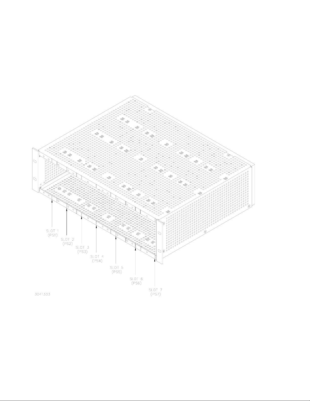
FIGURE 1-1. RA 19-7B RACK ADAPTER
iv RA 19-7B 011409
Page 7
1.1 SCOPE OF MANUAL
This manual contains instructions for the installation and operation of the RA 19-7B plug-in rack
adapter (Figure 1-1) used with HSF Series power supplies, manufactured by Kepco, Inc., Flushing, New York, U.S.A.
SECTION 1 - INTRODUCTION
1.2 GENERAL DESCRIPTION
FIGURE 1-1.
Kepco Series RA 19-(X)B rack adapters are specifically designed for the installation of Kepco
HSF Series Power Supplies into 19-inch EIA standard equipment racks. The RA 19-7B Model is
designed to accommodate a mix of 50 or 100 Watt (1/8 rack) and 150 Watt (1/6 rack) HSF
power supplies. Some standard configurations are listed below: (see Table 1-2 for filler panels to
cover unused slots):
• Three 1/6 rack modules (slots 5-7) and up to four 1/8 rack modules (slots 1-4) (Figure 1-
2)
• Four 1/6 rack modules (slots 4-7), one or two 1/8 rack modules (slots 1, 2, slot 3 empty),
and filler panel RFP 19-12
• Two 1/6 rack modules (slots 6,7), up to five 1/8 rack modules (slots 1-5), and filler panel
RFP 19-24
• One 1/6 rack module (slot 7), up to six 1/8 rack modules (slots 1-6) and two filler panels
RFP 19-24
NOTE: Contact Kepco Applications Engineering for assistance with non-standard configura-
tions not listed above.
The rack adapter is user-configurable for parallel, series, or independent power supply operation. Forced current sharing and OR’ing diodes for N+1 redundancy are built into the HSF power
supplies. User-configurable keying ensures that only the correct power supply can be installed
in a keyed slot.
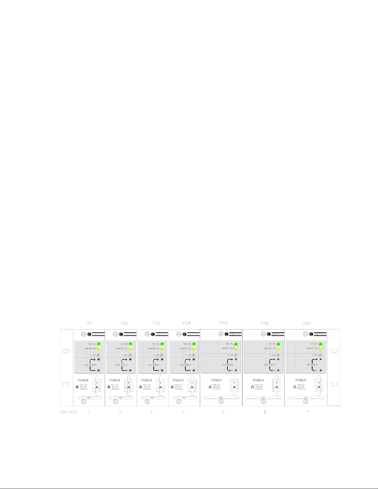
FIGURE 1-2. RA 19-7B RACK ADAPTER WITH HSF POWER SUPPLIES INSTALLED (TYPICAL)
RA 19-7B 011409 1-1
Page 8

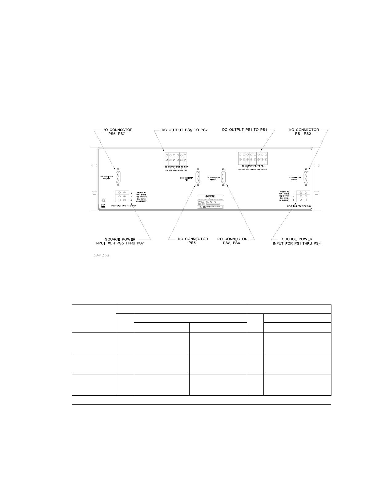
1.3 ELECTRICAL
The internal PCB back plate has connectors which interface directly with the power and signal
connectors of HSF Series power supplies, permitting hot swappable insertion and extraction.
The other side of the back plate assembly, available from the rear, contains the fixed power and
signal connections. Figure 1-3 illustrates the interconnections provided by the RA 19-7B Rack
Adapter. Dual input terminal blocks on the back plate assembly (Figure 1-4) distribute input
power to each group of three or four power supplies.
All mechanical specifications are contained in the mechanical outline drawing: Figure 1-5
FIGURE 1-3. RA 19-7B INTERCONNECTIONS, SIMPLIFIED DIAGRAM
1.4 MECHANICAL
The rack adapter is equipped with mounting ears for mounting in EIA standard 19-inch racks.
For mounting in non-standard racks, consult Kepco Applications Engineering. The rack adapter
is not configured for slides. Optional blank filler panels (see Table 1-2) are available if the full
complement of power supplies is not utilized.
1-2 RA 19-7B 011409
Page 9
Mechanical dimensions, material, and finish of the RA 19-7B Rack Adapter is provided in Figure
1-5.
1.5 OPTIONS
Table 1-1 below describes the standard model options available with Series RA 19-B rack
adapters. For non-standard options, contact Kepco Applications Engineering for assistance.
FIGURE 1-4. RA 19-7B RACK ADAPTER REAR PANEL
TABLE 1-1. RACK ADAPTER OPTIONS
1/8 Rack Slots 1/6 Rack Slots
MODEL
RA 19-6B *
RA 19-7B
(see PAR. 1.2)6 (max)
RA 19-8B
* Contact Kepco Applications Engineering for assistance with non-standard configurations.
To ta l
HSF5-10, HSF12-4.2,
HSF15-3.4, HSF24-2.1,
HSF48-1
HSF5-10, HSF12-4.2,
8
HSF15-3.4, HSF24-2.1,
(max)
HSF48-1
Compatible HSF Models
50 Watt 100 Watt 150 Watts
HSF5-20, HSF12-8.3,
HSF15-6.6, HSF24-4.2,
HSF28-3.5, HSF48-2
HSF5-20, HSF12-8.3,
HSF15-6.6, HSF24-4.2,
HSF28-3.5, HSF48-2
To ta l
HSF5-30, HSF12-12,
6
HSF15-10, HSF24-6,
(max)
HSF28-5, HSF48-2.8
HSF5-30, HSF12-12,
4
HSF15-10, HSF24-6,
(max)
HSF28-5, HSF48-2.8
*
Compatible HSF Models
RA 19-7B 011409 1-3
Page 10

1.6 ACCESSORIES
Accessories for RA 19-7B Rack Adapters are listed in Table 1-2.
ACCESSORY PART NUMBER USE
Filler Panel (1/8 Rack) RFP 19-18 Cover unused 1/8 rack slot.
Filler Panel (1/6 Rack) RFP 19-16 Cover unused 1/6 rack slot.
Filler Panel (1/4 Rack) RFP 19-28 Cover two unused 1/8 rack slots.
Filler Panel (2/6 Rack) RFP 19-26 Cover two unused 1/6 rack slots.
Filler Panel (3/8 Rack) RFP 19-38 Cover three unused 1/8 rack slots.
Filler Panel (1/2 Rack) RFP 19-48 Cover 1/2 rack (four 1/8 rack slots or three 1/6 rack slots).
Filler Panel (1/12 Rack) RFP 19-12 Cover slot 3 when 1/6 rack module inserted in slot 4.
Filler Panel (1/24 Rack) RFP 19-24 Cover gap when 1/8 rack module inserted in slot 5 or 6.
TABLE 1-2. RA 19-7B ACCESSORIES
1-4 RA 19-7B 011409
Page 11
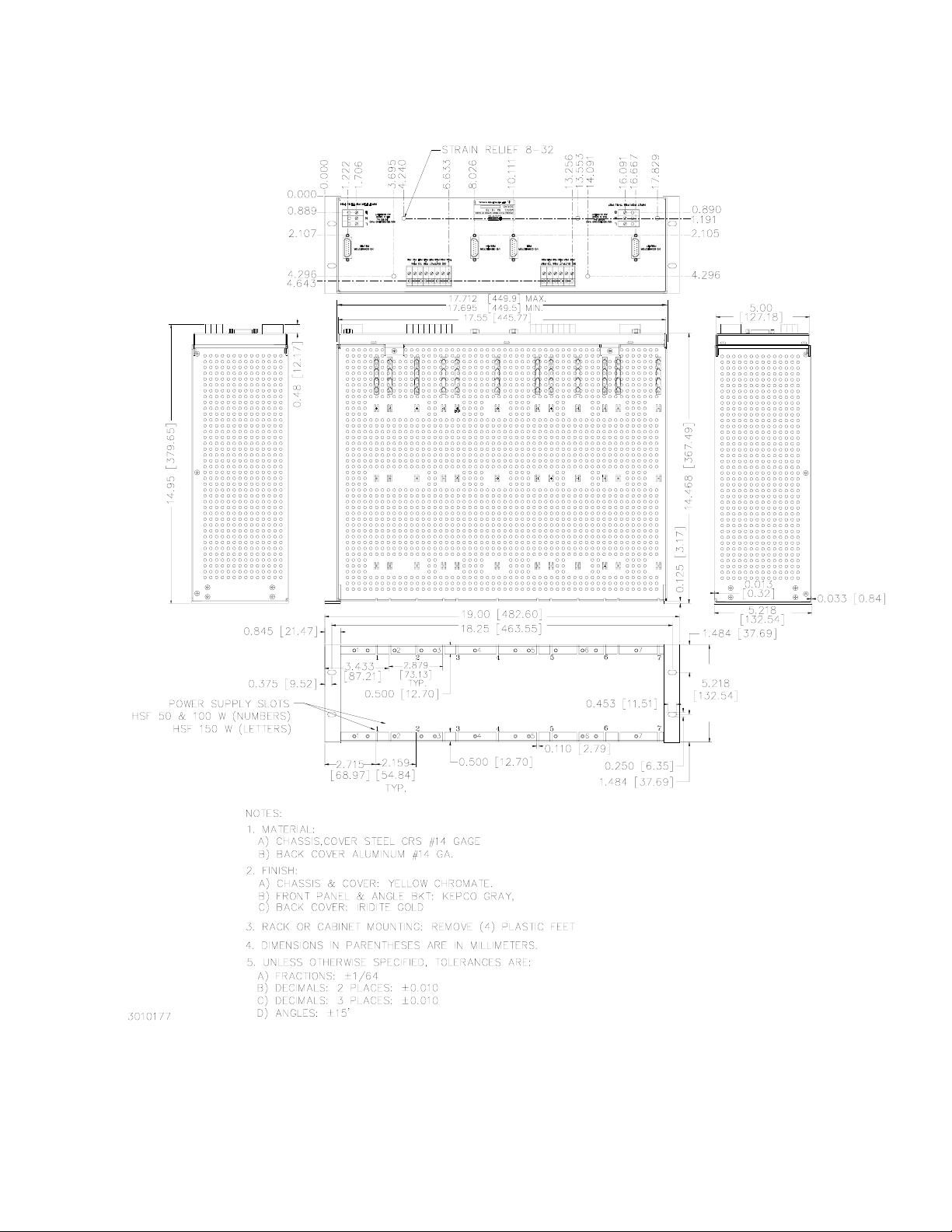
FIGURE 1-5. MECHANICAL OUTLINE DRAWING, RA 19-7B RACK ADAPTER
RA 19-7B 011409 1-5/(1-6 Blank)
Page 12

Page 13

SECTION 2 - INSTALLATION
2.1 UNPACKING AND INSPECTION
This equipment has been thoroughly inspected and tested prior to packing and is ready for
operation. After careful unpacking, inspect for shipping damage before attempting to operate. If
any indication of damage is found, file an immediate claim with the responsible transport service. See Table 2-1 for a list of equipment supplied.
TABLE 2-1. EQUIPMENT SUPPLIED
ITEM QUANTITY PART NUMBER
Rack Adapter 1 RA 19-7B
I/O Connector (Mating) 4 142-0449
Line cord (115 V a-c, 15A max, North American style plug, 6 ft) 2 118-0506
Instruction Manual 1 243-0890
Keying pins 8 108-0305
Hood for I/O Connector (Mating) P/N 142-0449 4 108-0204
2.2 CONFIGURING THE RACK ADAPTER
Prior to installation the rack adapter must be configured by the user. Configuration consists of
the following:
• For configurations that use multiple output voltages it is possible to key the rack adapter
to accept only a power supply with corresponding keying (see PAR 2.3).
• Configuring slots for independent, parallel, or series operation. This can be done by
means of internal DIP switches, or externally by wiring the associated I/O mating connector and DC OUTPUT terminals (see PAR. 2.4).
2.3 RACK ADAPTER KEYING INSTRUCTIONS
Series RA 19-(X)B rack adapters incorporate a keying mechanism to prevent accidental insertion of the incorrect model HSF power supply into any position. The HSF power supplies are
keyed by voltage at the factory. The keying mechanism will prevent engagement of any of the
HSF power supply's connectors with those on the rack adapter's back plate unless the key and
keyway align. The user can configure each power supply position of the rack adapter for the
desired voltage in the desired position (see Figure 2-1). First gain access to the interior components (PAR.2.3.1), then position the key as required (PAR. 2.3.2).
NOTE: After removing the rear panel, the keying pins can be accessed through the front of the
rack adapter, although it is recommended that the back plate be removed to gain easy
access to interior components.
2.3.1 DISASSEMBLY TO GAIN ACCESS TO INTERIOR COMPONENTS
NOTE: All power supplies must be removed prior to disassembly.
1. Remove eight spacers securing the four I/O connectors to the rear panel
RA 19-7B 011409 2-1
Page 14

2. Remove the four screws (two at the top and two at the bottom) securing the rear panel to the
chassis and separate the rear panel from the chassis (it is not necessary to remove the
ground connection (if present) between the rear panel and the chassis).
3. Remove seven screws (three at the top and four at the bottom) securing the back plate to the
chassis and remove the back plate to gain access to the interior components (see Figure 2-1)
FIGURE 2-1. BACKPLATE ASSEMBLY, INTERIOR VIEW
2.3.2 ESTABLISHING KEY POSITIONS
To establish the keying of any position, simply insert the key pin from the front and secure with
mounting nut (DISCARD LOCKWASHER) at the back plate using two ¼" nutdrivers or deep
sockets. HSF module keying is identified in Figure 2-1 and in the HSF operator's manual. DO
NOT ALTER THE KEYING AT THE POWER SUPPLY
2.4 SLOT CONFIGURATION
Configuring slots of the rack adapter for independent, parallel or series operation is accomplished either internally by means of DIP switches associated with each slot (see Figure 2-1),
2-2 RA 19-7B 011409
Page 15

or externally by connecting the appropriate pins of the associated I/O connector. DIP switch
functions are explained in Table 2-2. Refer to PAR. 2.3.1 to gain access to the DIP switches.
Slot configuration requires the following selection:
1. Select local or remote sensing (PAR. 2.4.1).
2. Select independent (PAR. 2.4.1), parallel (PAR. 2.4.2), or series (PAR. 2.4.3) operation.
3. Optional: Select close-on-failure or open-on-failure alarm (PAR. 2.4.4).
TABLE 2-2. CONFIGURATION DIP SWITCH* FUNCTIONS
DIP
SWITCH
POSITION
NOTES: 1. BOLD TYPE INDICATES FACTORY SETTINGS.
FUNCTION DIP SWITCH SET TO ON (CLOSED) DIP SWITCH SET TO OFF (OPEN)
2. For DIP switch A1, only positions 1 and 2 are active; all other positions are not connected.
1, 2
3, 4
6, 7
Required ON for independent operation with
Local Sensing. Position 1 connects V+ to S+,
Local /
Remote
Sensing
Selection
Connect
Sense
+ and –
in parallel
5
Current
Share
Close on
Failure
Alarm
Position 2 connects V– to S– (see PAR. 2.4.1.1).
Required ON for parallel configurations using DIP
switch settings to connect the sense leads in parallel. Position 3 connects +S to adjacent slot +S,
Position 4 connects –S to adjacent slot –S (see
PAR. 2.4.2.3.1 for local sensing, PAR. 2.4.2.3.3 for
remote sensing).
Required ON for parallel operation with forced current sharing (connects current share lines in parallel) unless connections are made via external
wires (see PAR. 2.4.2.2.1)
When set to ON, allows a single alarm to provide
failure indication (contact closure between N.O. pin
and COM pin) if any one of many power supplies
fails (see PAR. 2.4.4.1).
Position 1 and 2 required OFF for:
a) Independent configurations using Remote
Sensing (see PAR. 2.4.1.3).
b) Independent configurations using Local Sensing with user supplied connections from V+ to S+
and V– to S– (see PAR. 2.4.1.2).
c) All parallel configurations (sensing must be
established using external wires) (see PAR.
2.4.2.3).
d) All series connections (see PAR. 2.4.3).
Position 3 and 4 required OFF for all configurations except parallel configurations using
DIP switch settings to connect the sense
leads in parallel.
Required OFF for
a) independent and series configurations.
b) Parallel configurations with forced current
sharing using external wires to connect current share lines in parallel.
c. Parallel configurations without forced current sharing (current balancing).
When set to OFF, individual power supplies
produce closure between I/O connector N.O.
and COM pins upon failure (see PAR. 2.4.4.1).
When set to ON, allows a single alarm to provide
7, 8
RA 19-7B 011409 2-3
Open on
Failure
Alarm
failure indication (contact open between N.C. pin
and COM pin) if any one of many power supplies
fails. Position 7 of DIP switch 2 used for COM pin
connection between slots 1 and 2 (see PAR.
2.4.4.2).
When set to OFF, individual power supplies
produce open between I/O connector N.C. and
COM pins upon failure (see PAR. 2.4.4.2).
Page 16

2.4.1 INDEPENDENT OPERATION
The rack adapter is preconfigured at the factory for independent operation of all slots. DIP
switch positions 3, 4 and 5 associated with each slot must be set to OFF (open) for each power
supply to be operated independently.
NOTE: Either local or remote sensing must be connected for the HSF power supplies to
work properly.
The rack adapter is shipped from the factory with each power supply position configured for
local sensing (see Figure 2-2). Sensing for each slot can be configured independently:
• Local sensing using internal DIP switches
• Local sensing using external jumpers connected to the I/O mating connector or the DC
OUTPUT terminal block.
• Remote sensing
2-4 RA 19-7B 011409
Page 17

2.4.1.1 INDEPENDENT OPERATION - LOCAL SENSING USING INTERNAL DIP SWITCHES
The rack adapter slots are preconfigured at the factory for local sensing using internal DIP
switches. If a slot has been configured for other than local sensing using DIP switches and it is
necessary to reconfigure a slot for local sensing, simply set positions 1 and 2 of the DIP switch
associated with that slot to ON (closed). External sensing connections must be removed. When
set to ON (closed), DIP switch position 1 connects (V+) to (S+) and position 2 connects (V–) to
(S–). See Figure 2-1 for DIP switch locations. Figure 2-2 illustrates local sensing of PS6 and
PS7 by setting positions 1 and 2 of internal DIP switches E7 and F8 to ON (closed); positions 3
and 4 must be set to OFF (open). Position 5 (current share) must be set to OFF and positions 6,
7, and 8 (alarms) can be configured per PAR. 2.4.4.
FIGURE 2-2. INDEPENDENT OPERATION, LOCAL SENSING FOR PS6 AND PS7, USING INTERNAL
DIP SWITCHES, SIMPLIFIED DIAGRAM
RA 19-7B 011409 2-5
Page 18

2.4.1.2 INDEPENDENT OPERATION - LOCAL SENSING USING EXTERNAL WIRING
To configure a slot for local sensing using external wiring, first set internal DIP switch positions 1
and 2 of the DIP switches associated with that slot to OFF (open).
External local sensing is accomplished by connecting (V+) to (S+) and (V–) to (S–). This can be
done at either the mating I/O connector supplied (see Table 2-1) or the DC OUTPUT terminal
block. See Figure 2-1 for DIP socket locations. Figure 1-3 illustrates I/O connector pin assignments. Figure 2-3 illustrates local sensing of PS6 and PS7 using external jumpers connected to
the I/O mating connector.
NOTE: The internal DIP switch settings established at the factory for positions 1 and 2 of the
associated DIP switch MUST be changed to OFF (open) if local sensing using external
wiring is chosen.
Positions 3 and 4 (connecting sense lines in parallel) and Position 5 (current share) must be set
to OFF. Configure Positions 6, 7, and 8 (alarms) per PAR. 2.4.4.
FIGURE 2-3. INDEPENDENT OPERATION, LOCAL SENSING FOR PS6 AND PS7 USING
EXTERNAL JUMPERS AT I/O MATING CONNECTOR, SIMPLIFIED DIAGRAM
2-6 RA 19-7B 011409
Page 19

2.4.1.3 INDEPENDENT OPERATION - REMOTE SENSING
Remote sensing is accomplished by connecting +Load to (S+) and –Load to (S–). Figure 2-4
illustrates remote sensing for PS6 and PS7 using wires connected to the I/O mating connector.
NOTE: The internal DIP switch settings established at the factory for positions 1 and 2 of the
associated DIP switch MUST be changed to OFF (open) if remote sensing is chosen.
Positions 3 and 4 (connecting sense lines in parallel) and Position 5 (current share) must be set
to OFF. Configure Positions 6, 7, and 8 (alarms) per PAR. 2.4.4.
FIGURE 2-4. INDEPENDENT OPERATION, REMOTE SENSING FOR PS6 AND PS7 USING
EXTERNAL WIRING AT I/O MATING CONNECTOR, SIMPLIFIED DIAGRAM
RA 19-7B 011409 2-7
Page 20

2.4.2 PARALLEL OPERATION
HSF power supplies having identical voltage ratings can be connected in parallel to provide
redundant operation or increased output current to a common load. The power leads must be
connected in parallel externally (see PAR. 2.8.4.1). (Configurations using internal parallel busing
of the power leads are also possible; consult Kepco’s Applications Engineering for details.)
Three things must be considered when configuring the rack adapter for parallel operation:
• DC OUTPUT
• CURRENT SHARE
• SENSE
2.4.2.1 PARALLEL DC OUTPUT CONNECTIONS
The power leads must be connected in parallel externally (see PAR. 2.8.4.1). DC Output V(+)
and V(–) must be connected in parallel at the DC OUTPUT terminal block (see Figures 2-5
through 2-10).
2.4.2.2 PARALLEL CURRENT SHARE CONNECTIONS
The Current Share pins of the HSF power supplies must be connected together for parallel
operation. This can be done either internally using the DIP switches to configure adjacent slots
in parallel (PAR 2.4.2.2.1), or externally by wiring the I/O mating connector for configuring slots
1, 3, 4, and 6 (PAR. 2.4.2.2.2).
2-8 RA 19-7B 011409
Page 21

2.4.2.2.1 PARALLEL CURRENT SHARE - INTERNAL DIP SWITCHES
To configure adjacent slots, use the internal DIP switches to connect the Current Share bus.
Using internal DIP switches permits only adjacent power supplies be connected in parallel (e.g.,
PS1 and PS2, PS5 and PS6, PS5, PS6, and PS7, etc. PS1 and PS3 cannot be configured in
parallel using internal DIP switches). Contact Kepco Applications Engineering for non-standard
configurations using internal DIP switches.
To connect the current share lines locate DIP switches between the parallel-connected supplies
(see Figure 2-1) and set position 5 to ON (closed). Isolate the parallel group by locating the DIP
switches at both ends of the group and set positions 3 through 5 to OFF (open); refer to PAR.
2.4.2.3 for instructions on setting positons 3 and 4 for parallel connections. For example to connect PS5, PS6 and PS7 in parallel, set DIP switches F8 and E7, position 5, to ON (closed) (see
Figure 2-5); set DIP switch D5, positions 1 through 5 to OFF (open) (positions 1-2 of D5 must be
OFF because PS5 is in the parallel group and positions 3-5 isolate the parallel group).
FIGURE 2-5. PARALLEL OUTPUTS USING INTERNAL DIP SWITCHES TO PARALLEL SENSE
LINES AND CURRENT SHARE, PS5, PS6, AND PS7 (TYPICAL), SIMPLIFIED DIAGRAM
RA 19-7B 011409 2-9
Page 22

2.4.2.2.2 PARALLEL CURRENT SHARE - EXTERNAL WIRING
The Current Share lines for each supply must be connected in parallel at the I/O mating connector (pin 4) using external wiring (see Figure 2-6). Figure 2-6 is a simplified diagram of a typical
parallel configuration using external wiring at the I/O mating connector. Only slots 1, 4, 5, and
7 can be configured for parallel operation using external wiring. Position 5 of the associated
DIP switch must be set to OFF (open).
FIGURE 2-6. PARALLEL OUTPUTS USING EXTERNAL WIRING, TYPICAL
CONFIGURATION, SIMPLIFIED DIAGRAM
2-10 RA 19-7B 011409
Page 23

2.4.2.3 PARALLEL SENSE CONNECTIONS
NOTE: HSF power supply sense lines MUST be connected to the respective output terminals;
otherwise the power supplies will not work.
For parallel configurations the sense lines must be connected in parallel. This can be accomplished either by using the DIP switches (positions 3 and 4 set to ON) or by setting the DIP
switch positions 3 and 4 to OFF and using external wires. When configuring units to work in parallel, the current share bus (PAR. 2.4.2.2) must also be configured.
For local sensing (at the rack adapter) connect the sense lines in parallel using either the DIP
switches or external jumpers, then connect one +S and one –S from the I/O mating connector to
the DC OUTPUT terminal block using short jumpers.
For remote sensing (at the load) connect the sense lines in parallel using either the DIP
switches or external jumpers to connect the sense lines in parallel, then connect one +S and
one –S from the I/O connector to the load using external wires.
For both local and remote sensing Positions 1 and 2 of each DIP switch in the parallel configuration must be set to OFF (open); refer to Figure 2-1 to identify the DIP switch associated with a
corresponding slot.
See the following paragraphs for more details:
• PAR. 2.4.2.3.1: Parallel configurations using DIP switches to connect the sense lines in parallel and external wires to configure local sensing.
• PAR. 2.4.2.3.2: Parallel configurations using external wires to connect the sense lines in
parallel and external wires to configure local sensing.
• PAR. 2.4.2.3.3: Parallel configurations using DIP switches to connect the sense lines in parallel and external wires to configure remote sensing.
• PAR. 2.4.2.3.4: Parallel configurations using external wires to connect the sense lines in
parallel and external wires to configure remote sensing.
RA 19-7B 011409 2-11
Page 24

2.4.2.3.1 PARALLEL CONFIGURATIONS USING DIP SWITCHES TO CONNECT SENSE LINES IN PARALLEL AND EXTERNAL WIRES TO CONFIGURE LOCAL SENSING
Figure 2-7 is a simplified diagram of a typical parallel configuration using local sensing via external wires to connect V(+) to S(+), V(–) to S(–) and DIP switch settings to connect the sense
leads in parallel. This configuration requires the following:
1. For each supply in parallel set DIP switch positions 1 and 2 to OFF (open) (see Figure 2-1).
2. For each DIP switch between parallel-connected slots, set DIP switch positions 3 and 4 to
ON (closed) to connect sense leads in parallel (see Figure 2-1).
3. For each DIP switch between parallel-connected slots configure position 5 to connect the
current share bus by referring to PAR. 2.4.2.2.
4. Locate DIP switch(es) at both ends of the parallel group and set positions 3, 4, and 5 to OFF
(open) to isolate the group. (see Figure 2-1).
5. Configure Positions 6, 7, and 8 (alarms) of each DIP switch per PAR. 2.4.4.
6. Connect wire between I/O mating connector pin Sense (+) and corresponding power supply
V(+) terminal at DC OUTPUT terminal block.
7. Connect wire between I/O mating connector pin Sense (–) and corresponding power supply
V(–) terminal at DC OUTPUT terminal block.
FIGURE 2-7. TYPICAL PARALLEL CONNECTIONS USING EXTERNAL WIRES FOR
LOCAL SENSING AND DIP SWITCHES TO PARALLEL SENSE WIRES
2-12 RA 19-7B 011409
Page 25

2.4.2.3.2 PARALLEL CONFIGURATIONS USING EXTERNAL WIRES TO CONNECT SENSE LINES IN PARALLEL AND EXTERNAL WIRES TO CONFIGURE LOCAL SENSING
Figure 2-8 is a simplified diagram of a typical parallel configuration using local sensing via external wires to connect V(+) to S(+), V(–) to S(–) and jumpers connected to the I/O mating connecter to connect the sense leads in parallel. This configuration requires the following:
1. For each supply in parallel set DIP switch positions 1 and 2 to OFF (open) (see Figure 2-1).
2. For each DIP switch between parallel-connected slots, set DIP switch positions 3 and 4 to
OFF (open) (sense leads will be connected in parallel in steps 8 and 9) (see Figure 2-1).
3. For each DIP switch between parallel-connected slots configure position 5 to connect the
current share bus by referring to PAR. 2.4.2.2.
4. Locate DIP switch(es) at both ends of the parallel group and set positions 3, 4, and 5 to OFF
(open) to isolate the group. (see Figure 2-1).
5. Configure Positions 6, 7, and 8 (alarms) of each DIP switch per PAR. 2.4.4.
6. Connect wire between I/O mating connector pin Sense (+) and corresponding power supply
V (+) terminal at DC OUTPUT terminal block.
7. Connect wire between I/O mating connector pin Sense (–) and corresponding power supply
V (–) terminal at DC OUTPUT terminal block.
8. Connect short jumper across I/O mating connector Sense (+) pins.
9. Connect short jumper across I/O mating connector Sense (–) pins.
FIGURE 2-8. TYPICAL PARALLEL CONNECTIONS USING EXTERNAL WIRES FOR LOCAL SENSING
AND I/O MATING CONNECTOR JUMPERS TO PARALLEL SENSE WIRES
RA 19-7B 011409 2-13
Page 26

2.4.2.3.3 PARALLEL CONFIGURATIONS USING DIP SWITCHES TO CONNECT SENSE LINES IN PARALLEL AND EXTERNAL WIRES TO CONFIGURE REMOTE SENSING
Figure 2-9 is a simplified diagram of a typical parallel configuration using remote sensing via
external wires to connect V(+) to S(+), V(–) to S(–) and DIP switch settings to connect the sense
leads in parallel. This configuration requires the following:
1. For each supply in parallel set DIP switch positions 1 and 2 to OFF (open) (see Figure 2-1).
2. For each DIP switch between parallel-connected slots, set DIP switch positions 3 and 4 to
ON (closed) to connect sense leads in parallel (see Figure 2-1).
3. For each DIP switch between parallel-connected slots configure position 5 to connect the
current share bus by referring to PAR. 2.4.2.2.
4. Locate DIP switch(es) at both ends of the parallel group and set positions 3, 4, and 5 to OFF
(open) to isolate the group. (see Figure 2-1).
5. Configure Positions 6, 7, and 8 (alarms) of each DIP switch per PAR. 2.4.4.
6. Connect wire from I/O mating connector Sense (+) pin to V (+) at the load.
7. Connect wire from I/O mating connector Sense (–) pin to V (–) at the load.
FIGURE 2-9. TYPICAL PARALLEL CONNECTIONS, REMOTE SENSING
USING DIP SWITCHES TO PARALLEL SENSE WIRES
2-14 RA 19-7B 011409
Page 27

2.4.2.3.4 PARALLEL CONFIGURATIONS USING EXTERNAL WIRES TO CONNECT SENSE LINES IN PARALLEL AND EXTERNAL WIRES TO CONFIGURE REMOTE SENSING
Figure 2-10 is a simplified diagram of a typical parallel configuration using remote sensing via
external wires to connect V(+) to S(+), V(–) to S(–) and jumpers connected to the I/O mating
connector to connect the sense leads in parallel. This configuration requires the following:
1. For each supply in parallel set DIP switch positions 1 and 2 to OFF (open) (see Figure 2-1).
2. For each DIP switch between parallel-connected slots, set DIP switch positions 3 and 4 to
OFF (open) (sense leads will be connected in parallel in steps 8 and 9) (see Figure 2-1).
3. For each DIP switch between parallel-connected slots, configure position 5 to connect the
current share bus by referring to PAR. 2.4.2.2.
4. Locate DIP switch(es) at both ends of the parallel group and set positions 3, 4, and 5 to OFF
(open) to isolate the group. (see Figure 2-1).
5. Configure Positions 6, 7, and 8 (alarms) of each DIP switch per PAR. 2.4.4.
6. Connect short jumper across I/O mating connector Sense (+) pins.
7. Connect short jumper across I/O mating connector Sense (–) pins.
8. Connect wire from I/O mating connector Sense (+) pin to V (+) at the load.
9. Connect wire from I/O mating connector Sense (–) pin to V (–) at the load.
FIGURE 2-10. TYPICAL PARALLEL CONNECTIONS, REMOTE SENSING USING I/O MATING
CONNECTOR JUMPERS TO PARALLEL SENSE WIRES
RA 19-7B 011409 2-15
Page 28

2.4.3 SERIES OPERATION
HSF power supplies may be connected in series to obtain higher output voltages. Series configurations can only be accomplished by external wiring of the I/O mating connector. Blocking
diodes are incorporated in the HSF power supplies. V+ of one supply must be connected to V–
of the next supply at the DC OUTPUT terminal block.
DIP switches (positions 1 through 5) between series-connected supplies and at both ends of the
series-connected group must be set to OFF (open). Sensing can be either local or remote
(PAR. 2.4.1.3). Local sensing requires external wiring (PAR.2.4.1.2). Figure 2-11 illustrates
PS5, PS6, and PS7 connected in series.
FIGURE 2-11. SERIES CONFIGURATION, SIMPLIFIED DIAGRAM
2-16 RA 19-7B 011409
Page 29

2.4.4 ALARM CONFIGURATIONS
The HSF Power Supplies each provide a normally closed (N.C.) and normally open (N.O.) line
referenced to common (COM) for use as an alarm at the users discretion. The N.C. line opens
upon failure, the N.O. line closes upon failure. The RA 19-7B is configured at the factory for
independent operation of these lines. It is possible to configure these alarm lines to allow multiple power supplies to provide a failure indication using the N.O. (close on failure) lines, N.C
(open on failure) lines, or both. Each alarm circuit can be configured in two ways: either by internal DIP switches or by external wiring of the I/O mating connector. Use external wiring of the I/O
mating connector if DIP switch specifications noted in the following CAUTION will be exceeded.
CAUTION: The user is responsible for ensuring that the alarm circuit does not exceed
the HSF alarm relay switching specifications: 1A @ 30V d-c or 0.5A @ 125V
a-c. If the alarm circuit is configured using the rear panel DIP switches, the
user is responsible for ensuring that the alarm circuit does not exceed DIP
switch specifications: 100mA, 50V d-c, maximum.
2.4.4.1 N.O. ALARM LINE (CLOSE ON FAILURE)
The N.O. and COM line of each HSF supply provide a closed contact (short circuit) upon failure.
To configure multiple power supplies so that a failure of any supply produces a failure indication,
it is necessary to connect the N.O. lines in parallel and the COM lines in parallel.
2.4.4.1.1 CLOSE ON FAILURE USING INTERNAL DIP SWITCHES
Close on failure for multiple power supplies can be accomplished by setting DIP switch positions
6 and 7 to ON (closed). associated with each adjacent slot included in the alarm circuit. For
example, for PS1 and PS2, set DIP switch 2, positions 6 and 7 to ON (closed). The failure indication (short circuit) will be present across both N.O.1 and COM1, and N.O.2 and COM2. Figure
2-12 is a simplified diagram illustrating a close on failure alarm configuration for seven power
supplies using internal DIP switches.
2.4.4.1.2 CLOSE ON FAILURE USING EXTERNAL WIRING AT I/O MATING CONNECTOR
Close on failure for multiple power supplies can be accomplished by wiring N.O. and COM in
parallel at the I/O mating connector. DIP switches associated with slots included in the alarm circuit must have positions 6 and 7 set to OFF (open). The failure indication (short circuit) will be
present across any pair of N.O. and COM lines. Figure 2-13 is a simplified diagram illustrating a
close on failure alarm configuration for seven power supplies using external wiring at the I/O
mating connector.
RA 19-7B 011409 2-17
Page 30

2-18 RA 19-7B 011409
FIGURE 2-12. CLOSE ON FAILURE ALARM CONFIGURATION USING INTERNAL DIP SWITCHES, SIMPLIFIED DIAGRAM
Page 31

AT I/O MATING CONNECTOR, SIMPLIFIED DIAGRAM
FIGURE 2-13. CLOSE ON FAILURE ALARM CONFIGURATION USING EXTERNAL WIRING
RA 19-7B 011409 2-19
Page 32

2.4.4.2 N.C. ALARM LINE (OPEN ON FAILURE)
The N.C and COM line of each HSF supply provide an open contact (open circuit) upon failure.
To configure multiple power supplies so that a failure of any supply produces a failure indication,
it is necessary to connect the N.C. line of one, with the COM line of the next power supply, so
the alarm line is connected in series.
2.4.4.2.1 OPEN ON FAILURE USING INTERNAL DIP SWITCHES
The close on failure alarm for multiple power supplies is accomplished by setting the associated
DIP switch, position 7 or 8, to ON (closed) for each slot included in the alarm circuit as indicated
in Figure 2-14. Setting DIP switch position 7 or 8 to ON (closed) connects the N.C. line to the
COM line of the adjacent power supply. Figure 2-14 illustrates an open on failure alarm configuration for seven power supplies using internal DIP switch settings.
CAUTION: The user is responsible for ensuring that the alarm circuit does not exceed
DIP switch specifications: 100mA, 50V d-c, maximum.
To configure only PS1, PS2 and PS3 as open on failure, set position 7 of DIP switch for slot 2
(2) and position 8 of DIP switch for slot 3 (B3) to ON (closed). The failure indication (open circuit) will be present across N.C.1 and COM 3.
2.4.4.2.2 OPEN ON FAILURE USING EXTERNAL WIRING OF I/O MATING CONNECTOR
Figure 2-15 illustrates an open on failure alarm configuration using external wiring of the I/O
mating connectors for seven power supplies. It is necessary to set DIP switch position 8 to OFF
(open) for each slot included in the open on failure alarm circuit.
2-20 RA 19-7B 011409
Page 33

FIGURE 2-14. OPEN ON FAILURE ALARM CONFIGURATION USING INTERNAL DIP SWITCHES, SIMPLIFIED DIAGRAM
RA 19-7B 011409 2-21
Page 34

2-22 RA 19-7B 011409
AT I/O MATING CONNECTOR, SIMPLIFIED DIAGRAM
FIGURE 2-15. OPEN ON FAILURE ALARM CONFIGURATION USING EXTERNAL WIRING
Page 35

2.5 TERMINATIONS
All input, output and control terminations are located on the rear panel of the rack adapter (see
Figure 1-4).
2.6 COOLING
The HSF power supplies mounted within the rack adapter are maintained within their operating
temperature range by means of convection cooling. ALL OPENINGS AROUND THE RACK
ADAPTER CASE MUST BE KEPT CLEAR OF OBSTRUCTION TO ENSURE PROPER AIR
CIRCULATION. Care must be taken that the ambient temperature, which is the temperature of
the air immediately surrounding the rack adapter, does not rise above the specified limits for the
operating load conditions of the installed HSF power supplies. Kepco recommends providing
additional space above and below the rack adapter where possible when the rack adapter is
fully populated.
2.7 INSTALLATION (Refer to "Mechanical Outline Drawing," Figure 1-5.)
The rack adapter mounts directly to EIA standard 19" racks via the two mounting ears; two
screws are required per mounting ear for proper support.
Provide adequate clearance around case and ensure that the temperature immediately surrounding the unit does not exceed the maximum specified ambient temperature for the operating conditions of the installed power supplies.
RACK ADAPTER SHOULD BE MOUNTED BEFORE INSTALLING POWER SUPPLIES.
2.8 WIRING INSTRUCTIONS
Interconnections between an a-c power source and a stabilized power supply, and between the
power supply and its load are as critical as the interface between other types of electronic equipment. If optimum performance is expected, certain rules for the interconnection of source,
power supply and load must be observed by the user. These rules are described in detail in the
following paragraphs and in the operating instructions for HSF Series power supplies.
2.8.1 SAFETY GROUNDING
Local, national and international safety rules dictate the grounding of the metal cover and case
of any instrument connected to the a-c power source, when such grounding is an intrinsic part of
the safety aspect of the instrument. The instructions below suggest wiring methods which comply with these safety requirements; however, in the event that the specific installation for the
power system involves differences with the recommended wiring, it is the customer's responsibility to ensure that all applicable electric codes for safety grounding requirements are met.
2.8.2 SOURCE POWER CONNECTIONS
CAUTION
CAUTION
THE SERIES RA 19-(X)B DOES NOT INCORPORATE ANY SAFETY INTERRUPT DEVICES.
PROTECTION OF INPUT WIRING REQUIRES USER-CONFIGURED SAFETY INTERRUPTS.
When used in conjunction with Kepco HSF series power supplies, these rack adapters can be
operated from single phase 95-264 V a-c or 125-370V d-c source power without adjustment or
RA 19-7B 011409 2-23
Page 36

modification. Source power is applied to two 3-terminal terminal blocks at the rear panel and
distributed as indicated in Figure 1-3. Wires must be sized according to expected current. Wire
size range is 20-10 AWG; torque to 6 lb-in (0.6 N•M) maximum. The terminals are labeled L, N,
and G. Their functions are:
• Terminal G (Ground) is the safety ground connection for the Series RA 19-(X)B. It is
connected to the Series RA 19-(X)B chassis and to the safety ground terminal of the
input power connector for each of power supply mounting positions via the PCB backplane. Terminal G must be connected to safety ground in order to ensure proper grounding of the HSF power supplies.
• Terminals L (Line Phase) and N (Neutral) are connected to the input power entry con-
nectors. Source power is provided to the power supplies indicated by the label on the
rear panel. The source power connectors are independent of each other, allowing the
user complete flexibility in wiring for common or redundant input power configurations.
The following standard wiring configuration is recommended by Kepco as being compliant with
applicable national and international safety standards. Please consult local electrical codes for
wire current ratings and other specific requirements:
• Connect Terminal G of each Series RA 19-(X)B input power terminal block to safety
ground
• Connect a separate wire pair from each side of the input power to the L/N terminal pair of
the input power terminal block.
• Where 115V a-c source power is used, Kepco recommends the use of the line cords, P/
N 118-0506 supplied (North American style plug, 15A maximum, 6 ft. long).
• Wire size is determined by the maximum rated source current for each HSF power supply and the number of power supplies installed. For lower system power configurations,
smaller wire can be used; contact Kepco Applications Engineering for assistance.
2.8.3 CONTROL SIGNAL CONNECTIONS
Access to the control signal (I/O) connector for each HSF power supply is provided via the 15pin D-subminiature connectors on the rear panel of the rack adapter (see Figure 1-4). Four mating connectors (Kepco P/N 142-0449) and associated protective hoods (P/N 108-0204) are provided in a plastic bag. Consult PAR. 2.4 and the HSF operator's manual for instructions on
wiring and use of these control lines.
2.8.4 OUTPUT LOAD CONNECTIONS
Load connections to the rack adapters are achieved via two terminal blocks located on the
backplate assembly. Wires must be sized according to expected current. Wire size range is 2010 AWG; torque to 6 lb-in (0.6 N•M) maximum. (Sensing connections are made through the I/O
connector, PAR. 2.8.3)
NOTE!
REGARDLESS OF OUTPUT CONFIGURATION, OUTPUT SENSE
LINES MUST BE PROPERLY CONNECTED FOR OPERATION
2-24 RA 19-7B 011409
Page 37

2.8.4.1 PARALLEL/REDUNDANT OPERATION
WARNING
Removal of an HSF power supply from a “live” system must be done only by
authorized service personnel. Dangerous voltages may be accessible
through the open slot after a power supply is removed.
HSF power supplies having identical voltage ratings can be connected in parallel to provide
redundant operation or increased output current to a common load. Maximum output current for
each terminal pair of the DC OUTPUT terminal blocks is 30 Amperes. Connect (+) to (+) and (–
) to (–) at the DC OUTPUT terminal block (see Figure 2-5).
NOTE: Verify that Sense leads are connected (see PAR. 2.4.2.3). An external bus is required
where current exceeds 30 Amperes.
2.8.4.2 SERIES/INDEPENDENT OPERATION
The rack adapter can be used for either independent or series operation of HSF power supplies;
it is factory configured for independent operation using local sensing. To select remote sensing,
refer to PAR. 2.4.1.3.
For series operation, connect (+) and (–) terminals at the DC OUTPUT terminal block of power
supplies to be connected in series (see Figure 2-11). The HSF power supplies are equipped
with blocking diodes which allow series operation without further modification. The RA 19-(X)B
Series rack adapter is designed to safely handle a maximum output voltage of 500 Volts.
2.8.4.3 MIXED OPERATION
The design of the Series RA 19-(X)B rack adapters permits the user to configure HSF power
supplies for almost any combination of independent, series and parallel operation, both within a
single rack adapter and between different RA 19-(X)B rack adapters, within the limits of the HSF
operation envelope and the current and voltage ratings specified in PAR.s 2.8.4.1 and 2.8.4.2.
The user must ensure that the requirements for each configuration stated above are met. If any
questions or problems arise, the user is encouraged to contact the Kepco Applications Engineering group for technical assistance.
2.9 INSTALLING HSF POWER SUPPLIES
WARNING
Removal of an HSF power supply from a “live” system must be done only by
authorized service personnel. Dangerous voltages may be accessible
through the open slot after a power supply is removed.
Refer to Figure 1-1, for proper slot positions applicable to the RA 19-7B Rack Adapter. Insert
HSF power supply in selected slot until power supply front panel is flush with rack adapter chassis and secure with two phillips screws on power supply.
2.10 SHIPPING
The rack adapter may be shipped with power supplies installed only after the HSF power supplies have been securely fastened to the rack adapter (PAR. 2.9). Contact Kepco Applications
Engineering if further assistance is required.
RA 19-7B 011409 2-25/(2-26 Blank)
Page 38

Page 39

You must register your product to comply with the terms of the warranty. Either fill out the form
below and mail or fax to Kepco, or for rapid on-line registration go to:
http://www.kepcopower.com/warranty.htm
PRODUCT PURCHASED:
Model Number)______________________________________
Serial Number_______________________________________
PURCHASE INFORMATION:
Date Purchased:_____________________________________
Date Received:______________________________________
REQUEST ADDITIONAL INFORMATION
Send complete Catalog
Have Sales Engineer Call
Contact via: E-Mail Telephone Fax S-mail
REGISTER TO:
Registered by:________________________________________
Company Name:______________________________________
Street: ______________________________________________
City:________________________________________________
State:_______________________________________________
Country:_____________________________________________
Zip:_________________________________________________
E-mail: ______________________________________________
FAX:____________________________________________
Phone: _________________________________________
WHAT INFLUENCED YOUR CHOICE OF THIS POWER SUPPLY?
Previous Experience (which Kepco Models do you have?)
______________________________________________________
Kepco Catalog or Brochure?__________________________
Sales Representative?
______________________________________________________
______________________________________________________
Magazines (which ones?)_____________________________
______________________________________________________
Trade Shows (which ones?)___________________________
Directory?__________________________________________
Kepco 5 Year Warranty
This is to certify that we, KEPCO, INC., (hereinafter called “Company”), Flushing, NY
11355 USA, warrants for a period of FIVE YEARS, this instrument known as:
MODEL: __________________________________________
SERIAL NO. _________________________________________
The Company’s products are warranted for a period of five years from date of delivery to
be free from defects in materials and workmanship and to conform to the specifications
furnished or approved by the Company. Liability under this warranty shall be limited to
the repair or replacement of any defective product at Company’s option.
If any defect within this warranty appears within the warranty period, the Purchaser shall
promptly notify the Company in writing. No material will be accepted for repair or
replacement without written authorization of the Company.
Web Site
Other (please explain):_____________________________
What products would you like to see Kepco make?
____________________________________________________
____________________________________________________
____________________________________________________
CUT HERE
Upon such authorization, and in accordance with instructions of the Company, parts or
materials for which replacement is requested shall be returned to the Company for
examination, with shipping charges prepaid by the Purchaser. Final determination as to
whether a product is actually defective rests with the Company.
This warranty does not extend to any product which has been subjected to misuse,
neglect, accident, improper installation, or use in violation of instructions furnished by
the Company. The warranty does not extend to, or apply to, any unit which has been
repaired or altered outside of the Company’s factory by persons not expressly approved
by the Company.
THE WARRANTY HEREIN CONTAINED IS IN LIEU OF AND EXCLUDES ALL OTHER
WARRANTIES, EXPRESS, IMPLIED OR STATUTORY, INCLUDING WITHOUT
LIMITATION THE WARRANTY OF MERCHANTABILITY.
THIS KEPCO PRODUCT IS WARRANTED FOR FIVE YEARS!
KEPCO, INC. 131-38 SANFORD AVENUE, FLUSHING,
NY 11355 USA
MST SERIES 1/14/09 1
E-mail: hq@kepcopower.com
Tel. 718-461-7000 Fax. 718-767-1102
URL: http://www.kepcopower.com
Page 40

KEPCO, INC.
131-38 SANFORD AVE.
FLUSHING, NY 11355 USA
FOLD HERE
Please
place
stamp
here
CUT HERE
 Loading...