

Page 1

INSTRUCTION MANUAL
RA 19-1U
RACK ADAPTER
HOT SWAP RACK ADAPTER FOR 1U HSF SERIES POWER SUPPLIES
KEPCO INC.
An ISO 9001 Company.
RACK ADAPTER
ORDER NO. REV. NO.
IMPORTANT NOTES:
1) This manual is valid for the following Model and associated serial numbers:
MODEL SERIAL NO. REV. NO.
2) A Change Page may be included at the end of the manual. All applicable changes and
revision number changes are documented with reference to the equipment serial numbers. Before using this Instruction Manual, check your equipment serial number to identify
your model. If in doubt, contact your nearest Kepco Representative, or the Kepco Documentation Office in New York, (718) 461-7000, requesting the correct revision for your
particular model and serial number.
3) The contents of this manual are protected by copyright. Reproduction of any part can be
made only with the specific written permission of Kepco, Inc.
Data subject to change without notice.
MODEL
RA 19-1U
KEPCO®
©2013, KEPCO, INC
P/N 243-1025R3
KEPCO, INC. ! 131-38 SANFORD AVENUE ! FLUSHING, NY. 11355 U.S.A. ! TEL (718) 461-7000 ! FAX (718) 767-1102
email: hq@kepcopower.com
! World Wide Web: http://www.kepcopower.com
THE POWER SUPPLIER™
Page 2

Page 3

TABLE OF CONTENTS
SECTION PAGE
SECTION 1 - INTRODUCTION
1.1 Scope of Manual ..................................................................................................................................... 1-1
1.2 General Description................................................................................................................................. 1-1
1.3 Mechanical .............................................................................................................................................. 1-1
1.4 Electrical.................................................................................................................................................. 1-1
1.5 Safety ...................................................................................................................................................... 1-2
1.6 RoHS Compliance................................................................................................................................... 1-2
1.7 Accessories ............................................................................................................................................. 1-3
1.8 Options .................................................................................................................................................... 1-3
SECTION 2 - INSTALLATION
2.1 Unpacking and Inspection ....................................................................................................................... 2-1
2.2 Configuring the Rack Adapter ................................................................................................................. 2-1
2.3 Rack Adapter Keying Instructions ........................................................................................................... 2-1
2.3.1 Establishing Key Positions................................................................................................................. 2-2
2.4 Slot Configuration.................................................................................................................................... 2-2
2.4.1 Independent Operation ...................................................................................................................... 2-3
2.4.1.1 Independent Operation - Local Sensing Using Rear Panel DIP switches ................................... 2-4
2.4.1.2 Independent Operation - Local Sensing Using External Wiring ................................................... 2-5
2.4.1.3 Independent Operation - Remote Sensing .................................................................................. 2-6
2.4.2 Parallel Operation.............................................................................................................................. 2-7
2.4.2.1 Parallel DC OUTPUT Connections.............................................................................................. 2-7
2.4.2.2 Parallel Current Share Connections ............................................................................................ 2-7
2.4.2.2.1 Parallel Current Share - Rear Panel DIP Switches....................................................................2-8
2.4.2.2.2 Parallel Current Share - External Wiring....................................................................................2-9
2.4.2.3 Sense Connections for Parallel Configurations ........................................................................... 2-10
2.4.2.3.1 Parallel Configuration Using DIP Switches to Connect Sense Lines in
Parallel and External Wires to Configure Local Sensing........................................................2-11
2.4.2.3.2 Parallel Configurations using External Wires to Connect Sense Lines
in Parallel and External Wires to Configure Local Sensing ....................................................2-12
2.4.2.3.3 Parallel Configurations using DIP Switches to Connect Sense Lines in
Parallel and External Wires to Configure Remote Sensing....................................................2-13
2.4.2.3.4 Parallel Configurations using External Wires to Connect Sense Lines
in Parallel and External Wires to Configure Remote Sensing ................................................2-14
2.4.3 Series Operation................................................................................................................................ 2-15
2.4.4 Alarm Configurations ......................................................................................................................... 2-17
2.4.4.1 N.O. Alarm Line (Close on Failure).............................................................................................. 2-17
2.4.4.1.1 Close on Failure Using Rear Panel Dip Switches......................................................................2-17
2.4.4.1.2 Close on Failure Using External Wiring at I/O Mating Connector ..............................................2-19
2.4.4.2 N.C. Alarm Line (Open on Failure) .............................................................................................. 2-20
2.4.4.2.1 Open on Failure Using Rear Panel Dip Switches ......................................................................2-20
2.4.4.2.2 Open on Failure Using External Wiring of I/O Mating Connector...............................................2-21
2.5 Current Monitoring (-1URC and -1URY Models only) ............................................................................. 2-22
2.6 Remote On-Off (-1URX and -1URY Models only)................................................................................... 2-23
2.7 Terminations............................................................................................................................................ 2-24
2.8 Cooling .................................................................................................................................................... 2-24
2.9 Installation ............................................................................................................................................... 2-24
2.9.1 Installing 1U HSF Power Supplies..................................................................................................... 2-24
2.10 Wiring Instructions................................................................................................................................... 2-24
RA 19-1U 020413 i
Page 4

TABLE OF CONTENTS
SECTION PAGE
2.10.1 Safety Grounding.............................................................................................................................. 2-25
2.10.2 Source Power Connections .............................................................................................................. 2-25
2.10.2.1 EMI Compliance.......................................................................................................................... 2-26
2.10.3 Control Signal Connections .............................................................................................................. 2-26
2.10.4 Output Load Connections ................................................................................................................. 2-26
2.10.4.1 Reducing Ripple and Noise......................................................................................................... 2-26
2.10.4.2 Parallel/Redundant Operation ..................................................................................................... 2-28
2.10.4.3 Series/Independent Operation .................................................................................................... 2-28
2.10.4.4 Mixed Operation.......................................................................................................................... 2-28
2.11 Removing/Replacing 1U HSF Power Supplies ....................................................................................... 2-28
2.12 Shipping.................................................................................................................................................. 2-28
ii RA 19-1U 020413
Page 5

LIST OF FIGURES
FIGURE TITLE PAGE
1-1 RA 19-1U Rack Adapter ............................................................................................................................... vi
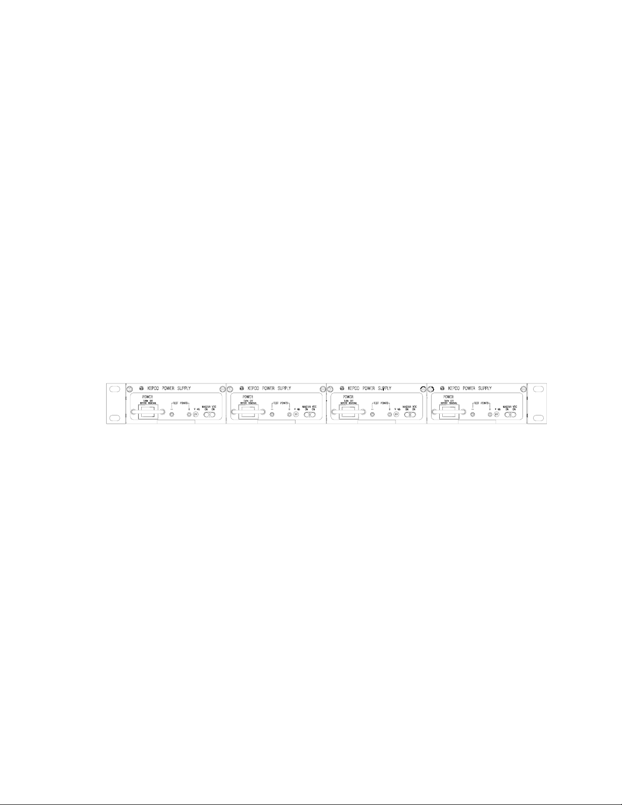
1-2 RA 19-1U Rack Adapter with 1U HSF Power Supplies Installed ................................................................ 1-1
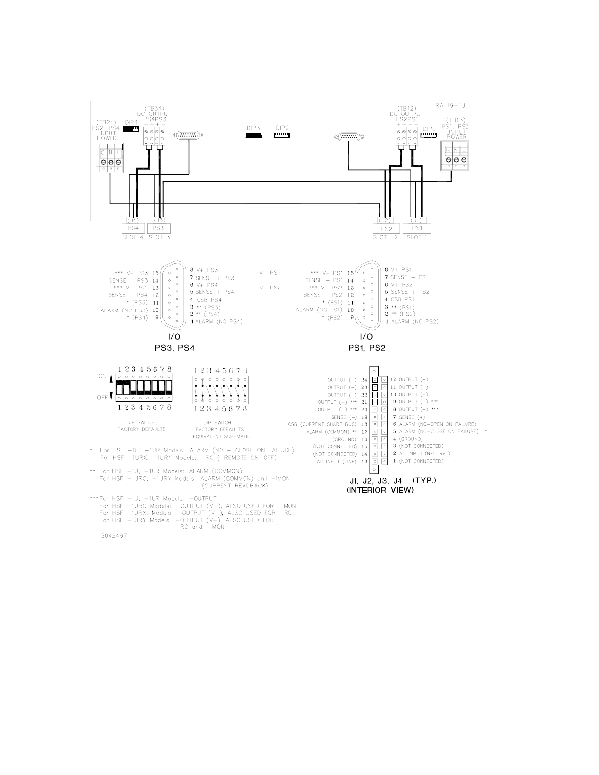
1-3 RA 19-1U Interconnections, Simplified Diagram......................................................................................... 1-2
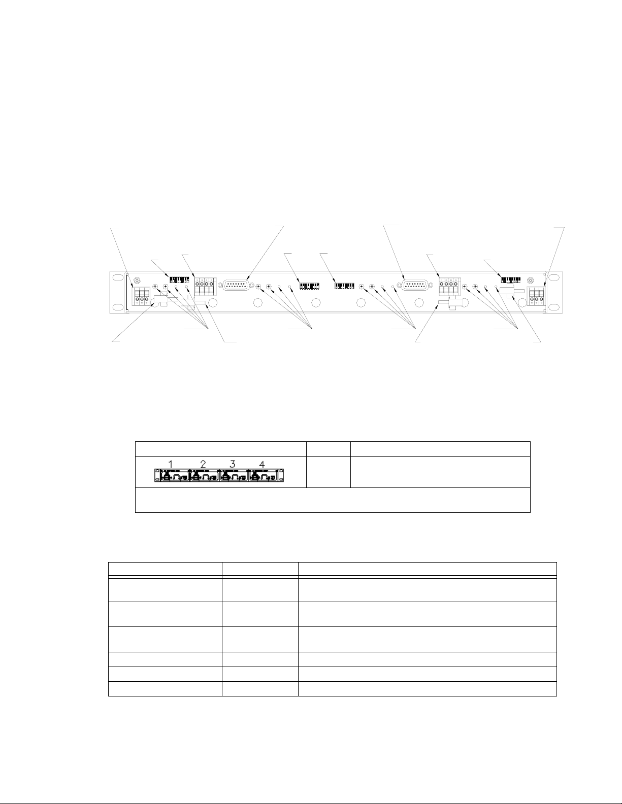
1-4 RA 19-1U Rack Adapter Rear Panel .......................................................................................................... 1-3
1-5 Mechanical Outline Drawing, RA 19-1U Rack Adapter............................................................................... 1-4
1-6 RA 19-1U Schematic Diagram.................................................................................................................... 1-7
2-1 RA 19-1U Rack Adapter Keying ................................................................................................................. 2-2
2-2 Independent Operation, Local Sensing for PS1 and PS2 using
Rear Panel DIP switches, Simplified Diagram ........................................................................................ 2-4
2-3 Independent Operation, Local Sensing for PS1 and PS2 using
External Jumpers at I/O Mating Connector, Simplified Diagram ............................................................. 2-5
2-4 Independent Operation, Remote Sensing for PS1 and PS2 using
External Wiring at I/O Mating Connector, Simplified Diagram................................................................. 2-6
2-5 Parallel Outputs Using Rear Panel DIP Switches to Parallel sense
lines and current share, PS1 and PS2 (Typical), Simplified Diagram ..................................................... 2-8
2-6 Parallel Outputs Using External Wiring, Typical Configuration, Simplified Diagram ................................... 2-9
2-7 Typical Parallel Connections Using External Wires for
Local Sensing and DIP switches to Parallel Sense Wires....................................................................... 2-11
2-8 Typical Parallel Connections using External Wires for Local Sensing
and I/O Mating Connector Jumpers to Parallel Sense Wires ................................................................... 2-12
2-9 Typical Parallel Connections, Remote Sensing using DIP Switches to Parallel Sense Wires.................... 2-13
2-10 Typical Parallel Connections, Remote Sensing using I/O Mating
Connector Jumpers to Parallel Sense Wires........................................................................................... 2-14
2-11 Series Configuration, Simplified Diagram ................................................................................................... 2-16
2-12 Close on Failure Alarm Configuration Using Rear Panel Dip Switches, Simplified Diagram ...................... 2-18
2-13 Close on Failure Alarm Configuration Using External Wiring at I/O Mating
Connector, Simplified Diagram................................................................................................................. 2-19
2-14 Open on Failure Alarm Configuration Using Rear Panel Dip Switches, Simplified Diagram ...................... 2-20
2-15 Open on Failure Alarm Configuration Using External Wiring
at I/O Mating Connector, Simplified Diagram ........................................................................................... 2-21
2-16 Using Current Monitoring (Typical), -1URC and -1URY Models only ......................................................... 2-22
2-17 Using Remote On-Off (Typical), -1URX and -1URY Models only............................................................... 2-23
2-18 Ripple and Noise Measurement Setup Diagram......................................................................................... 2-27
RA 19-1U 020413
iii/(iv Blank)
Page 6

Page 7

LIST OF TABLES
TABLE TITLE PAGE
1-1 Compatible 1U HSF Power Supplies ..........................................................................................................1-3
1-2 RA 19-1U Accessories ................................................................................................................................1-3
2-1 Equipment Supplied ....................................................................................................................................2-1
2-2 Rear Panel DIP Switch Functions ...............................................................................................................2-3
2-3 Sense Resistor Values ................................................................................................................................2-22
RA 19-1U 020413 v
Page 8

S
L
O
T
1
S
L
O
T
2
S
L
O
T
3
S
L
O
T
2
4
0
3
9
4
5
4
FIGURE 1-1. RA 19-1U RACK ADAPTER
vi RA 19-1U 020413
Page 9
1.1 SCOPE OF MANUAL
This manual contains instructions for the installation and operation of the RA 19-1U plug-in rack
adapter (Figure 1-1) used with 1U HSF Series power supplies, manufactured by Kepco, Inc.,
Flushing, New York, U.S.A. Unless otherwise noted, 1U HSF refers to the following models -1U,
-1UR, -1URT, -1URC, -1URX and -1URY.
SECTION 1 - INTRODUCTION
1.2 GENERAL DESCRIPTION
FIGURE 1-1.
Kepco RA 19-1U rack adapters are specifically designed for the installation of Kepco 1U HSF
Series Power Supplies into 19-inch EIA-RS-310D standard equipment racks. The RA 19-1U
Model accommodates up to four 50W, 100W or 150W 1U HSF power supplies (Figure 1-2).
The rack adapter is user-configurable for parallel, series, or independent power supply operation. Up to four identical units may connected in parallel. Multiple rack adapters may be paralleled for additional current capacity. Forced current sharing and OR’ing diodes for N+1
redundancy are built into the 1U HSF power supplies. Redundant a-c inputs are provided to
deliver independent source power to each power supply in a redundant pair. User-configurable
keying ensures that only the correct power supply can be installed in a keyed slot.
PS1 PS2
3042496
FIGURE 1-2. RA 19-1U RACK ADAPTER WITH 1U HSF POWER SUPPLIES INSTALLED
PS3
PS4
1.3 MECHANICAL
The rack adapter is equipped with mounting ears for mounting in EIA-RS-310D standard 19inch racks. For mounting in non-standard racks, consult Kepco Applications Engineering. The
rack adapter is not configured for slides. Optional blank filler panels (see Table 1-2) are available if the full complement of power supplies is not utilized.
Mechanical dimensions, material, and finish of the RA 19-1U Rack Adapter is provided in Figure
1-5.
1.4 ELECTRICAL
An internal PCB back plate mounts connectors which interface directly with the power and signal connectors of 1U HSF Series power supplies, permitting hot swappable insertion and
extraction. The other side of the back plate assembly, available from the rear, contains the fixed
power and signal connections. Figure 1-3 illustrates the interconnections provided by the RA
19-1U Rack Adapter. Dual input terminal blocks on the back plate assembly (Figure 1-4) distribute input power to each of the four powers supplies. Figure 1-6 is a schematic diagram of
the RA 19-1U rack Adapter.
RA 19-1U 020413 1-1
Page 10
All mechanical and electrical specifications are contained in the mechanical outline drawing:
Figure 1-5. See Figure 1-6 for electrical schematic diagram.
I/O CONNECTOR,
PS3, PS4
I/O CONNECTOR,
PS1, PS2
FIGURE 1-3. RA 19-1U INTERCONNECTIONS, SIMPLIFIED DIAGRAM
1.5 SAFETY
Certified to UL 60950-1, 1st Edition, 2007-10-31 (Information Technology Equipment - Safety Part 1: General Requirements) and CSA C22.2 No. 60950-1-03, 1st Edition, 2006-07 (Information Technology Equipment - Safety - Part 1: General Requirements). Units are CE marked per
the Low Voltage Directive (LVD), 2006/95/EC (LVD) and 2004/108/EC (EMC). [The standards
do not apply with either DC input operation or with a-c input frequency above 66Hz.]
1.6 RoHS COMPLIANCE
RoHS 5 of 6 compliant to EU directive 2011/65/EU if used as component within telecommunication systems.
1-2 RA 19-1U 020413
Page 11
1.7 ACCESSORIES
Accessories for RA 19-1U Rack Adapters are listed in Table 1-2; see also Table 2-1 for additional accessories supplied with the unit.
1.8 OPTIONS
Table 1-1 below describes the standard model options available with the RA 19-1U rack
adapter. For non-standard options, contact Kepco Applications Engineering for assistance.
SOURCE POWER
INPUT FOR
PS2 AND PS4
PS4 KEYING
CABLE CLAMP*
AC INPUT
PS2 AND PS4
3042498
DIP 4
I/O CONNECTOR,
PS3, PS4
DC OUTPUT
PS3, PS4
DIP 3 DIP 2
PS3 KEYING PS2 KEYING PS1 KEYING
CABLE CLAMP*
DC OUTPUT
PS2 AND PS4
* CABLE CLAMPS ARE USER
INSTALLED.
I/O CONNECTOR,
PS1, PS2
DC OUTPUT
PS1, PS2
CABLE CLAMP*
DC OUTPUT
PS1 AND PS2
FIGURE 1-4. RA 19-1U RACK ADAPTER REAR PANEL
TABLE 1-1. COMPATIBLE 1U HSF POWER SUPPLIES
RA 19-1U RACK ADAPTER SLOT COMPATIBLE POWER SUPPLIES
1, 2, 3, 4 HSF-1UR 50W, 100W and 150W Series
HSF-1U 50W and 100W Series
NOTES: 1. Contact Kepco Applications Engineering for assistance with non-standard configurations.
2. RA 19-1U is compatible with HSF-1U, -1UR, -1URC, -1URX, and -1URY models.
SOURCE POWER
INPUT FOR
PS1 AND PS3
DIP 1
CABLE CLAMP*
AC INPUT
PS1 AND PS3
TABLE 1-2. RA 19-1U ACCESSORIES
ACCESSORY PART NUMBER USE
Screw, Thread forming
(4-40, 0.75 in. long, PHPH)
Cable Clamp, Nylon, with
release lever
101-0480
108-0422
Line cord 118-0506
Connector 142-0449 Mating Connector for I/O connector. Two (2) supplied with unit.
Filler Panel (1/4 Rack) RFP 19-1U-14 Cover one unused 1/4 rack slot.
Filler Panel (1/2 Rack) RFP 19-1U-12 Cover two unused 1/4 rack slots.
RA 19-1U 020413 1-3
Module Keying. eight (8) supplied with unit. Installed by user (see PAR.
2.3).
Support weight of AC input and DC output cables. Four (4) supplied
with unit to be installed by user as desired (see Figure 1-4)
Supply 115 V a-c source power to rack adapter. Two (2) supplied with
unit.
Page 12
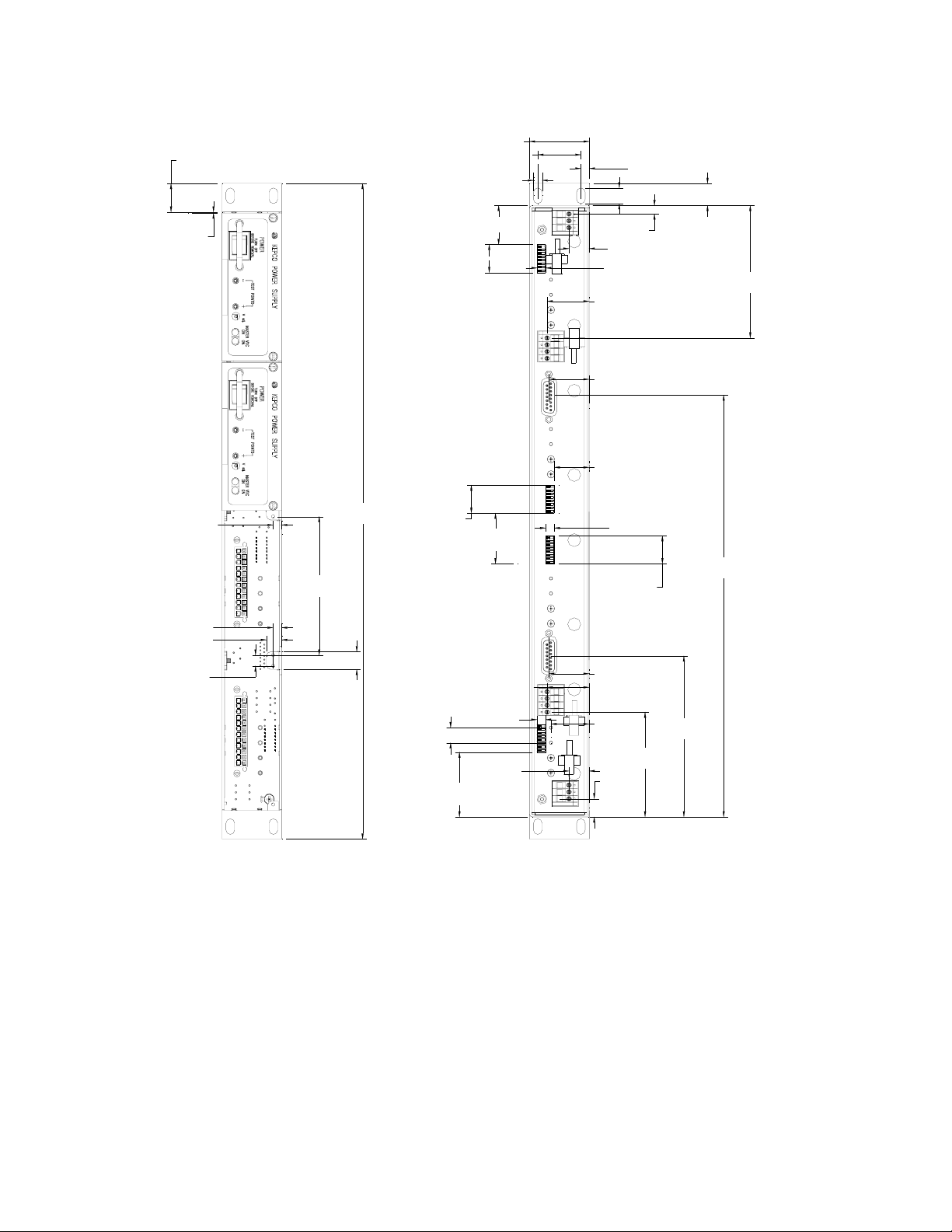
0.830 [21.1]
1.735 [44.1]
1.250 [31.8]
0.250 [6.4]
0.243 [6.2]
0.453 [11.5]
0.641 [16.3]
0.031 [0.8]
0.250 [6.4]
0.250 [6.4]
0.444 [11.3]
0.311 [7.9]
19.000 [482.6]
4.016 [102.0]
0.511 [13.0]
0.812 [20.6]
1.130 [28.7]
0.812 [20.6]
1.465 [37.2]
1.218 [30.9]
0.247 [6.3]
0.582 [14.8]
0.250 [6.4]
3.840 [97.5]
1.218 [30.9]
1.166 [29.6]
1.009 [25.6]
0.250 [6.4]
12.225 [310.5]
0.812 [20.6]
1.166 [29.6]
0.250 [6.4]
0.438 [11.1]
0.582 [14.8]
1.877 [47.7]
1.106
[28.1]
3.037 [77.1]
0.527
[13.4]
4.665 [118.5]
NOTES:
1. MATERIAL:
-CHASSIS,COVER,BACKPLATE 0.064" THK ALUM. 5052-H32
-PCB 0.063" THK. FR-4
2. FINISH
-IRIDITE GOLD ON ALL METAL PARTS.
-BACKPLATE SILKSCREEN BLACK INK.
3. IF KEYING IS REQUIRED USE THE INCLUDED SELF FORMING SCREWS 4-40x3/4" (1010480) AS PER FIGURE 2-1.
MAX. TORQUE 5 lbxin (0.6 Nxm).
4. MODULE ARE SECURED FOR HOT SWAP OPERATION WITH CAPTIVE PANEL SCREWS 4-40.
MAX. TORQUE 2 lbxin (0.23 Nxm).
5. FOR SHIPPING OR HIGH VIBRATION AND SHOCK ENVIRONMENTS,MODULES CAN EACH BE SECURED
WITH ONE FLAT HEAD SCREW 100~ , 6-32x1/4" MIN. to 1/2" MAX. LONG.(KEPCO P/N 1010408 ) OR SIMILAR.
THE SCREW WILL BE INSTALLED THRU THE COUNTERSUNK HOLES IN THE BOTTOM PAN.
6. DIMENSIONS ARE IN INCHES [DIMENSIONS IN BRACKETS ARE IN MILLIMETERS].
7. TOLERANCES (UNLESS OTHERWISE SPECIFIED): 3 PLACES: ±0.005, 2 PLACES ±0.01, FRACTIONS: ±1/64"
3010247
FIGURE 1-5. MECHANICAL OUTLINE DRAWING, RA 19-1U RACK ADAPTER (SHEET 1 OF 2)
1-4 RA 19-1U 020413
Page 13
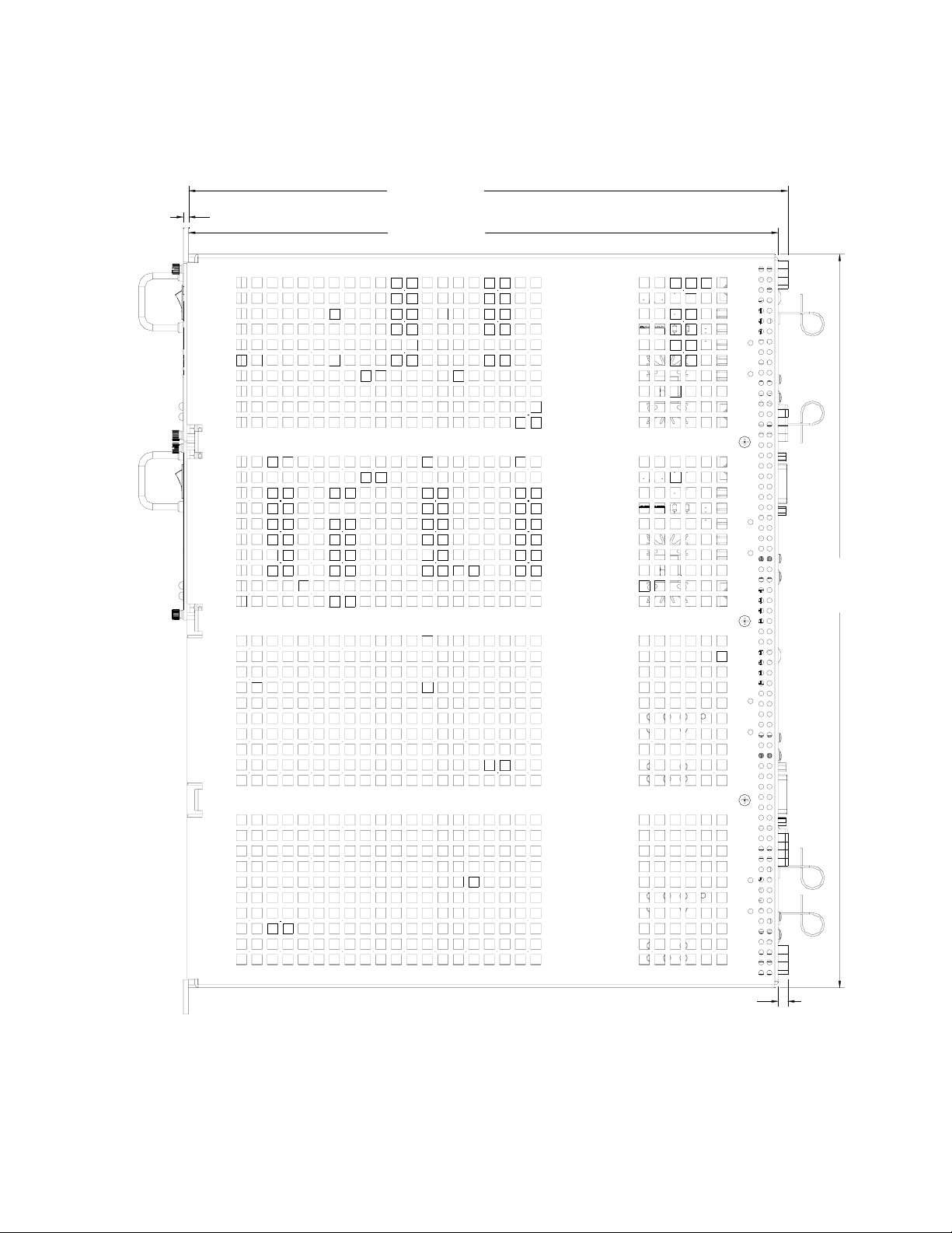
0.125 [3.2]
14.497 [368.2]
14.267 [362.4]
17.715 max
[449.9 max.]
0.230 [5.8]
3010247
FIGURE 1-5. MECHANICAL OUTLINE DRAWING, RA 19-1U RACK ADAPTER (SHEET 2 OF 2)
RA 19-1U 020413 1-5/(1-6 Blank)
Page 14

Page 15

SECTION 1 - w
N1
123456789
1314151617181920212223
101112
JP39
JP40
101112
TB-IN24
L4
24
123
J3
PROPRIETARY DATA
N4
GND
GND
L4
N4
123456789
1314151617181920212223
JP6
101112
©2010, KEPCO, INC
J4
24
TB-IN13
123
L1
N1
GND
JP44
JP43
JP36
JP35
J1
24
JP1
JP2
N2
L2
123456789
1314151617181920212223
J2
101112
24
JP38
JP37
L3
JP4
JP3 JP5
JP42
JP41
N3
123456789
1314151617181920212223
V-2
V+2
S+2
V-1
V+1
815714613512411310291
S-2
NC1
S-1
CSB1
NO1
COM1
NO2
COM2
S+1
NC2 OR RET
DIP1
S+1
1
S-1
2
3
4
5
6
7
8 9
-2
+1
-1
+2
123
4
TB12
1
V+1
16
2
V-1
15
3
14
4
13
5
12
6
11
7
10
8
V+2
V-2
S+1
S-1
CSB
NO1
COM1
NC1
DIP2
1
JP16
1
2
2
3
JP14
3
4
JP13
4
5
JP12
5
6
JP11
6
7
JP10
7
8
JP9
8 9
S+2
16
S-2
15
S+2
14
S-2
13
CSB
12
NO2
11
COM2
10
COM2
V+3
V-3
S+2
S-2
CSB
NO2
COM2
NC2
1
2
3
4
5
6
7
8 9
NC2
DIP3
JP25
JP24JP15
JP23
JP22
JP21
JP20
JP19
JP18
JP17
+4L1-4
+3
-3
123
4
TB34
DIP4
1
S+3
16
2
S-3
15
3
S+3
14
4
S-3
13
5
CSB
12
6
NO3
11
7
COM3
10
8
COM3
RET
V+4
V-4
S+3
S-3
CSB
NO3
COM3
NC3
NC3
1
JP34
1
2
JP33
2
3
JP32
3
4
JP31
4
5
JP30
5
6
JP29
6
7
JP28
7
8
JP27
8 9
JP26
S+4
16
S-4
15
S+4
14
S-4
13
CSB
12
NO4
11
COM4
10
COM4
RET
RET NC4
JP45
COM4
S-4
NC3
CSB4
S+4
V+4
V-4
COM3
S-3
S+3
V-3
V+3
815714613512411310291
NO3
NO4
NC4
3020630
P-12
P-34
FIGURE 1-6. RA 19-1U SCHEMATIC DIAGRAM
020413 6-7
1-7/1-8 (Blank)
6-6/6-7
Page 16

Page 17

SECTION 2 - INSTALLATION
2.1 UNPACKING AND INSPECTION
This equipment has been thoroughly inspected and tested prior to packing and is ready for
operation. After careful unpacking, inspect for shipping damage before attempting to operate. If
any indication of damage is found, file an immediate claim with the responsible transport service. See Table 2-1 for a list of equipment supplied.
TABLE 2-1. EQUIPMENT SUPPLIED
ITEM QUANTITY PART NUMBER
Rack Adapter 1 RA 19-1U
I/O Connector (Mating) 2 142-0449
Line cord (115 V a-c, 15A max, North American style plug, 6 ft.) 2 118-0506
Instruction Manual 1 243-1025
Keying screws (4-40 x 0.75 in., thread forming) 8 101-0480
Hood for I/O Connector (Mating) P/N 142-0449 2 108-0204
Cable clamp with release latch 4 108-0422
2.2 CONFIGURING THE RACK ADAPTER
Prior to installation the rack adapter must be configured by the user. Configuration consists of
the following:
• For configurations that use multiple output voltages it is possible to key the rack adapter
to accept only a power supply with corresponding keying (see PAR 2.3).
• Configuring slots for independent, parallel, or series operation. This can be done by
means of DIP switches mounted on the rear panel, or externally by wiring the associated
I/O mating connector and DC OUTPUT terminals (see PAR. 2.4).
2.3 RACK ADAPTER KEYING INSTRUCTIONS
RA 19-1U rack adapters incorporate a keying mechanism to prevent accidental insertion of the
incorrect model 1U HSF power supply into any position. The 1U HSF power supplies are keyed
by voltage at the factory. The keying mechanism will prevent engagement of any of the 1U HSF
power supply's connectors with those on the rack adapter's back plate unless the key and keyway align. The key pins are on the 1U HSF power supply and are set at the factory. DO NOT
ALTER THE KEYING AT THE POWER SUPPLY. The keyway is established by installing screws
(provided) so that the only open holes match the power supply pins. The user can configure
each power supply slot for the desired voltage in the desired position. Figure 1-4 shows the
location of key positions for each slot and Figure 2-1 shows the configuration required for voltage selection.
RA 19-1U 020413 2-1
Page 18

2.3.1 ESTABLISHING KEY POSITIONS
To establish the keying of any position, simply install the 4-40 x 0.75 in. thread-forming screws
(Kepco P/N 101-0480) into the corresponding holes as indicated in Figure 2-1. DO NOT OVERTIGHTEN these screws (max torque 5 in.-lbs. (0.6 N x m). DO NOT ALTER THE KEYING AT
THE POWER SUPPLY.
FIGURE 2-1. RA 19-1U RACK ADAPTER KEYING
2.4 SLOT CONFIGURATION
Configuring slots of the rack adapter for independent, parallel or series operation is accomplished either by means of DIP switches mounted on the rear panel associated with each slot
(see Figure 1-3), or externally by connecting the appropriate pins of the associated I/O mating
connector. DIP switch functions are explained in Table 2-2.
Slot configuration requires the following selection:
1. Select independent (PAR. 2.4.1), parallel (PAR. 2.4.2), or series (PAR. 2.4.3) operation.
2. Select local or remote sensing; PAR. 2.4.1 (independent), 2.4.2, (parallel) or 2.4.3, (series).
3. Optional: Select close-on-failure or open-on-failure alarm (PAR. 2.4.4).
4. Current Monitoring (Models -1URC and -1URY only, see PAR. 2.5).
5. Remote On-Off (Models -1URX and -1URY only, see PAR. 2.6).
2-2 RA 19-1U 020413
Page 19

DIP
SWITCH
POSITION
TABLE 2-2. REAR PANEL DIP SWITCH FUNCTIONS
FUNCTION DIP SWITCH SET TO ON (CLOSED) DIP SWITCH SET TO OFF (OPEN)
NOTE: BOLD TYPE INDICATES FACTORY SETTINGS.
1, 2
3, 4
5
6, 7
8
Local /
Remote
Sensing
Selection
Connect
Sense
+ and –
in parallel
Current
Share
Close on
Failure
Alarm
** Open on
Failure
Alarm
Required ON for independent operation with
Local Sensing. Position 1 connects V+ to S+,
Position 2 connects V– to S– (see PAR.
2.4.1.1).
Required ON for parallel configurations using DIP
switch settings to connect the sense leads in parallel. Position 3 connects +S to adjacent slot +S,
Position 4 connects –S to adjacent slot –S (see
PAR. 2.4.2.3.1 for local sensing, PAR. 2.4.2.3.3
for remote sensing).
Required ON for parallel operation (connects current share lines in parallel) unless connections are
made via external wires (see PAR. 2.4.2.2.1)
When set to ON, allows a single alarm to provide
failure indication (contact closure between N.O.
pin and COM pin) if any one of many power supplies fails (see PAR. 2.4.4.1).
** When set to ON, allows a single alarm to provide failure indication (contact open between N.C.
pin and COM pin) if any one of many power supplies fails (see PAR. 2.4.4.2).
Position 1 and 2 required OFF for:
a) Independent configurations using Remote
Sensing (see PAR. 2.4.1.3).
b) Independent configurations using Local Sensing with user supplied connections from V+ to S+
and V– to S– (see PAR. 2.4.1.2).
c) All parallel configurations (sensing must be
established using external wires) (see PAR.
2.4.2.3).
d) All series connections (see PAR. 2.4.3).
Position 3 and 4 required OFF for all configurations except parallel configurations using DIP
switch settings to connect the sense leads in
parallel.
Required OFF for
a) independent and series configurations.
b) Parallel configurations using external wires
to connect current share lines in parallel.
When set to OFF, individual power supplies
produce closure between I/O connector N.O.
and COM pins upon failure (see PAR. 2.4.4.1).
** When set to OFF, individual power supplies
produce open between I/O connector N.C. and
COM pins upon failure (see PAR. 2.4.4.2).
** Not applicable for HSF-1URX and -1URY models (see PAR 2.6).
2.4.1 INDEPENDENT OPERATION
The rack adapter is preconfigured at the factory for independent operation of all slots. DIP
switch positions 3, 4 and 5 associated with each slot must be set to OFF (open) for each power
supply to be operated independently.
NOTE: Either local or remote sensing must be connected for the 1U HSF power supplies
to work properly.
The rack adapter is shipped from the factory with each power supply position configured for
local sensing (see Figure 2-2). Sensing for each slot can be configured independently:
• Local sensing using rear panel DIP switches
• Local sensing using external jumpers connected to the I/O mating connector or the DC
OUTPUT terminal block.
• Remote sensing
RA 19-1U 020413 2-3
Page 20

2.4.1.1 INDEPENDENT OPERATION - LOCAL SENSING USING REAR PANEL DIP SWITCHES
The rack adapter slots are preconfigured at the factory for local sensing using rear panel DIP
switches. If a slot has been configured for other than local sensing using DIP switches and it is
necessary to reconfigure it for local sensing, simply set positions 1 and 2 of the DIP switch associated with that slot to ON (closed). External sensing connections must be removed. When set
to ON (closed) DIP switch position 1 connects (V+) to (S+) and position 2 connects (V–) to (S–).
See Figure 1-3 for DIP switch locations. Figure 2-2 illustrates local sensing of PS1 and PS2 by
setting positions 1 and 2 of rear panel DIP 1 and 2 to ON (closed); positions 3 and 4 must be set
to OFF (open). Position 5 (current share) must be set to OFF and positions 6, 7, and 8 (alarms)
can be configured per PAR. 2.4.4.
FIGURE 2-2. INDEPENDENT OPERATION, LOCAL SENSING FOR PS1 AND PS2 USING
REAR PANEL DIP SWITCHES, SIMPLIFIED DIAGRAM
2-4 RA 19-1U 020413
Page 21

2.4.1.2 INDEPENDENT OPERATION - LOCAL SENSING USING EXTERNAL WIRING
To configure a slot for local sensing using external wiring, first set rear panel DIP switch positions 1 and 2 of the DIP switches associated with that slot to OFF (open).
External local sensing is accomplished by connecting (V+) to (S+) and (V–) to (S–). This can be
done at either the mating I/O connector supplied (see Table 2-1) or at the DC OUTPUT terminal
block. See Figure 1-3 for DIP socket locations. Figure 1-3 illustrates I/O connector pin assignments. Figure 2-3 illustrates local sensing of PS1 and PS2 using external jumpers connected to
the I/O mating connector.
NOTE: The rear panel DIP switch settings established at the factory for positions 1 and 2 of
the associated DIP switch MUST be changed to OFF (open) if this option is chosen.
Positions 3 and 4 (connecting sense lines in parallel) and Position 5 (current share) must be set
to OFF. Configure Positions 6, 7, and 8 (alarms) per PAR. 2.4.4.
FIGURE 2-3. INDEPENDENT OPERATION, LOCAL SENSING FOR PS1 AND PS2 USING
EXTERNAL JUMPERS AT I/O MATING CONNECTOR, SIMPLIFIED DIAGRAM
RA 19-1U 020413 2-5
Page 22

2.4.1.3 INDEPENDENT OPERATION - REMOTE SENSING
Remote sensing is accomplished by connecting +Load to (S+) and –Load to (S–). Figure 2-4
illustrates remote sensing for PS1 and PS2 using wires connected to the I/O mating connector.
NOTE: The rear panel DIP switch settings established at the factory for positions 1 and 2 of
the associated DIP switch MUST be changed to OFF (open) if this option is chosen.
Positions 3 and 4 (connecting sense lines in parallel) and Position 5 (current share) must be set
to OFF. Configure Positions 6, 7, and 8 (alarms) per PAR. 2.4.4.
FIGURE 2-4. INDEPENDENT OPERATION, REMOTE SENSING FOR PS1 AND PS2 USING
EXTERNAL WIRING AT I/O MATING CONNECTOR, SIMPLIFIED DIAGRAM
2-6 RA 19-1U 020413
Page 23

2.4.2 PARALLEL OPERATION
Up to four Identical 1U HSF power supplies can be connected in parallel to provide redundant
operation or increased output current to a common load. Blocking diodes are incorporated in
HSF -1U and -1UR power supplies. The power leads must be connected in parallel externally
(see PAR. 2.10.4.2). (Configurations using internal parallel busing are also possible; consult
Kepco’s Applications Engineering for details.) Three things must be considered when configuring the rack adapter for parallel operation:
• DC OUTPUT
• CURRENT SHARE
• SENSE
2.4.2.1 PARALLEL DC OUTPUT CONNECTIONS
The power leads must be connected in parallel externally (see PAR. 2.10.4.2). DC Output V(+)
and V(–) must be connected in parallel at the DC OUTPUT terminal block (see Figures 2-5
through 2-10).
2.4.2.2 PARALLEL CURRENT SHARE CONNECTIONS
The Current Share pins of the 1U HSF power supplies must be connected together for parallel
operation. This can be done using either the rear panel DIP switches to configure adjacent slots
in parallel (PAR 2.4.2.2.1), or externally by wiring the I/O mating connector for configuring slots
1 and 4 (PAR. 2.4.2.2.2).
RA 19-1U 020413 2-7
Page 24

2.4.2.2.1 PARALLEL CURRENT SHARE - REAR PANEL DIP SWITCHES
To configure adjacent slots, use the rear panel DIP switches to connect the Current Share bus.
Using rear panel DIP switches permits only adjacent power supplies be connected in parallel.
To connect the current share lines locate the applicable DIP switches: (see Figure 1-3) and set
position 3, 4, 5 to ON (closed). The example illustrated in Figure 2-5 shows two 50W units (slot
1 and slot 2) connected in parallel using rear panel DIP switches to configure the current share
bus, enabled via position 5 of DIP switch 2 for slots 1/2.
NOTE: If rear panel DIP switch positions 3, 4 are closed (ON), use only one pair of sense
lines to monitor voltage.
FIGURE 2-5. PARALLEL OUTPUTS USING REAR PANEL DIP SWITCHES TO PARALLEL SENSE
LINES AND CURRENT SHARE, PS1 AND PS2 (TYPICAL), SIMPLIFIED DIAGRAM
2-8 RA 19-1U 020413
Page 25

2.4.2.2.2 PARALLEL CURRENT SHARE - EXTERNAL WIRING
Only slots 1 and 4 can be configured for parallel operation using external wiring; To configure
slots 2 and 3 for parallel operation with current sharing the rear panel DIP switches must be
used (see PAR. 2.4.2.2.1). The Current Share lines for each supply must be connected
together at the I/O mating connector (pin 4) using external wiring (see Figure 2-6). Figure 2-6 is
a simplified diagram of a parallel configuration for slots 1 and 4 using external wiring at the I/O
mating connector.
I/O CONNECTOR,
PS3, PS4
I/O CONNECTOR,
PS1, PS2
FIGURE 2-6. PARALLEL OUTPUTS USING EXTERNAL WIRING, TYPICAL
CONFIGURATION, SIMPLIFIED DIAGRAM
RA 19-1U 020413 2-9
Page 26

2.4.2.3 SENSE CONNECTIONS FOR PARALLEL CONFIGURATIONS
NOTE: 1U HSF power supply sense lines MUST be connected to the respective output pins of
I/O connector; otherwise the power supplies will not work.
For parallel configurations the sense lines must be connected in parallel. This can be accomplished either by using the DIP switches (positions 3 and 4 set to ON) or by setting the DIP
switch positions 3 and 4 to OFF and using external wires. When configuring units to work in parallel, the current share bus (PAR. 2.4.2.2) must also be configured.
For local sensing (at the rack adapter) connect the sense lines in parallel using either the DIP
switches or external jumpers, then connect one +S and one –S from the I/O mating connector to
the DC OUTPUT terminal block using short jumpers.
For remote sensing (at the load) connect the sense lines in parallel using either the DIP
switches or external jumpers to connect the sense lines in parallel, then connect one +S and
one –S from the I/O connector to the load using external wires.
For both local and remote sensing Positions 1 and 2 of each DIP switch in the parallel configuration must be set to OFF (open); refer to Figure 1-3 to identify the DIP switch associated with a
corresponding slot.
See the following paragraphs for more details:
• PAR. 2.4.2.3.1: Parallel configurations using DIP switches to connect the sense lines in parallel and external wires to configure local sensing.
• PAR. 2.4.2.3.2: Parallel configurations using external wires to connect the sense lines in
parallel and external wires to configure local sensing.
• PAR. 2.4.2.3.3: Parallel configurations using DIP switches to connect the sense lines in parallel and external wires to configure remote sensing.
• PAR. 2.4.2.3.4: Parallel configurations using external wires to connect the sense lines in
parallel and external wires to configure remote sensing.
2-10 RA 19-1U 020413
Page 27

2.4.2.3.1 PARALLEL CONFIGURATION USING DIP SWITCHES TO CONNECT SENSE LINES IN PARALLEL AND EXTERNAL WIRES TO CONFIGURE LOCAL SENSING
Figure 2-7 is a simplified diagram of a typical parallel configuration using local sensing via external wires to connect V(+) to S(+), V(–) to S(–) and DIP switch settings to connect the sense
leads in parallel. This configuration requires the following:
1. For each supply in parallel set DIP switch positions 1 and 2 to OFF (open) (see Figure 1-3).
2. For each DIP switch between parallel-connected slots (DIP 2, DIP 3 and DIP 4), set DIP
switch positions 3 and 4 to ON (closed) to connect sense leads in parallel (see Figure 1-4).
3. For each DIP switch between parallel-connected slots configure position 5 to connect the
current share bus by referring to PAR. 2.4.2.2.
4. Configure Positions 6, 7, and 8 (alarms) of each DIP switch per PAR. 2.4.4.
5. Connect wire between I/O mating connector pin Sense (+) and corresponding power supply
V(+) terminal at DC OUTPUT terminal block.
6. Connect wire between I/O mating connector pin Sense (–) and corresponding power supply
V(–) terminal at DC OUTPUT terminal block.
FIGURE 2-7. TYPICAL PARALLEL CONNECTIONS USING EXTERNAL WIRES FOR
LOCAL SENSING AND DIP SWITCHES TO PARALLEL SENSE WIRES
RA 19-1U 020413 2-11
Page 28

2.4.2.3.2 PARALLEL CONFIGURATIONS USING EXTERNAL WIRES TO CONNECT SENSE LINES IN PARALLEL AND EXTERNAL WIRES TO CONFIGURE LOCAL SENSING
Figure 2-8 is a simplified diagram of a typical parallel configuration using local sensing via external wires to connect V(+) to S(+), V(–) to S(–) and jumpers connected to the I/O mating connector to connect the sense leads in parallel. This configuration requires the following:
1. For each supply in parallel set DIP switch positions 1 and 2 to OFF (open) (see Figure 1-3).
2. For each DIP switch between parallel-connected slots (DIP 2, DIP 3 and DIP 4), set DIP
switch positions 3 and 4 to OFF (open) (sense leads will be connected in parallel in steps 7
and 8) (see Figure 1-3).
3. For each DIP switch between parallel-connected slots configure position 5 to connect the
current share bus by referring to PAR. 2.4.2.2.
4. Configure Positions 6, 7, and 8 (alarms) of each DIP switch per PAR. 2.4.4.
5. Connect wire between I/O mating connector pin Sense (+) and corresponding power supply
V (+) terminal at DC OUTPUT terminal block.
6. Connect wire between I/O mating connector pin Sense (–) and corresponding power supply
V (–) terminal at DC OUTPUT terminal block.
7. Connect short jumper across I/O mating connector Sense (+) pins.
8. Connect short jumper across I/O mating connector Sense (–) pins.
FIGURE 2-8. TYPICAL PARALLEL CONNECTIONS USING EXTERNAL WIRES FOR LOCAL SENSING
AND I/O MATING CONNECTOR JUMPERS TO PARALLEL SENSE WIRES
2-12 RA 19-1U 020413
Page 29

2.4.2.3.3 PARALLEL CONFIGURATIONS USING DIP SWITCHES TO CONNECT SENSE LINES IN PARALLEL AND EXTERNAL WIRES TO CONFIGURE REMOTE SENSING
Figure 2-9 is a simplified diagram of a typical parallel configuration using remote sensing via
external wires to connect V(+) to S(+), V(–) to S(–) and DIP switch settings to connect the sense
leads in parallel. This configuration requires the following:
1. For each supply in parallel set DIP switch positions 1 and 2 to OFF (open) (see Figure 1-3).
2. For each DIP switch between parallel-connected slots (DIP 2, DIP 3, DIP 4), set DIP switch
positions 3 and 4 to ON (closed) to connect sense leads in parallel (see Figure 1-3).
3. For each DIP switch between parallel-connected slots configure position 5 to connect the
current share bus by referring to PAR. 2.4.2.2.
4. Configure Positions 6, 7, and 8 (alarms) of each DIP switch per PAR. 2.4.4.
5. Connect wire from I/O mating connector Sense (+) pin to V (+) at the load.
6. Connect wire from I/O mating connector Sense (–) pin to V (–) at the load.
FIGURE 2-9. TYPICAL PARALLEL CONNECTIONS, REMOTE SENSING
USING DIP SWITCHES TO PARALLEL SENSE WIRES
RA 19-1U 020413 2-13
Page 30

2.4.2.3.4 PARALLEL CONFIGURATIONS USING EXTERNAL WIRES TO CONNECT SENSE LINES IN PARALLEL AND EXTERNAL WIRES TO CONFIGURE REMOTE SENSING
Figure 2-10 is a simplified diagram of a typical parallel configuration using remote sensing via
external wires to connect V(+) to S(+), V(–) to S(–) and jumpers connected to the mating connector to connect the sense leads in parallel. This configuration requires the following:
1. For each supply in parallel set DIP switch positions 1 and 2 to OFF (open) (see Figure 1-3).
2. For each DIP switch between parallel-connected slots (DIP 2), set DIP switch positions 3
and 4 to OFF (open) (sense leads will be connected in parallel in steps 7 and 8) (see Figure
1-3).
3. For each DIP switch between parallel-connected slots, configure position 5 to connect the
current share bus by referring to PAR. 2.4.2.2.
4. Configure Positions 6, 7, and 8 (alarms) of each DIP switch per PAR. 2.4.4.
5. Connect short jumper across I/O mating connector Sense (+) pins.
6. Connect short jumper across I/O mating connector Sense (–) pins.
7. Connect wire from I/O mating connector Sense (+) pin to V (+) at the load.
8. Connect wire from I/O mating connector Sense (–) pin to V (–) at the load.
FIGURE 2-10. TYPICAL PARALLEL CONNECTIONS, REMOTE SENSING USING I/O MATING
CONNECTOR JUMPERS TO PARALLEL SENSE WIRES
2-14 RA 19-1U 020413
Page 31

2.4.3 SERIES OPERATION
HSF -1U and -1UR power supplies may be connected in series to obtain higher output voltages.
The RA 19-1U rack adapter is designed to safely handle a maximum output voltage of 500
Volts; contact Kepco applications engineering for additional information. The power supply with
the lowest rated value of maximum current establishes the maximum load current allowed.
Series configurations can only be accomplished by external wiring of the I/O mating connector.
V+ of one supply must be connected to V– of the next supply at the DC OUTPUT terminal block.
It is recommended that reverse diodes be connected at the output of each power supply connected in series.
The DC OUTPUT + terminal of one supply must be connected to DC OUTPUT – terminal of the
next supply. Each Power Supply in series must be protected by a reverse diode connected in
parallel with the output as shown in Figure 2-11. The diode protects against reverse voltages.
Protection diodes must conform to the following specifications:
•V
REV
> 2 x V
x N where V
NOM
is the output voltage of the HSF power supply and N
NOM
is the number of power supplies connected in series.
•I
FWD
> 1.5 x I
NOM
where I
is the output current of the HSF power supply.
NOM
DIP switches (positions 1 through 4) between series-connected supplies and at both ends of the
series-connected group must be set to OFF (open). Sensing can be either local or remote (PAR.
2.4.1.3). Local sensing requires external wiring (PAR.2.4.1.2). Figure 2-11 illustrates PS1, PS2
PS3 and PS4 connected in series.
RA 19-1U 020413 2-15
Page 32

FIGURE 2-11. SERIES CONFIGURATION, SIMPLIFIED DIAGRAM
2-16 RA 19-1U 020413
Page 33

2.4.4 ALARM CONFIGURATIONS
The 1U HSF Power Supplies each provide a normally closed (N.C.) and normally open (N.O.)
line referenced to common (COM) for use as an alarm at the users discretion. The N.C. line
opens upon failure, the N.O. line closes upon failure.
NOTE: HSF-1URX and -1URY models do not include the normally open (N.O.) line, so
close on failure configurations are not applicable.
The RA 19-1U is configured at the factory for independent operation of these lines. It is possible
to configure these alarm lines to allow multiple power supplies to provide a failure indication
using the N.O. (close on failure) lines, N.C (open on failure) lines, or both. Each alarm circuit
can be configured in two ways: either by rear panel DIP switches or by external wiring of the I/O
mating connector. Use external wiring of the I/O mating connector if DIP switch specifications
noted in the following CAUTION will be exceeded.
CAUTION: The user is responsible for ensuring that the alarm circuit does not exceed
the HSF alarm relay switching specifications: 1A @ 30V d-c or 0.5A @ 125V
a-c. If the alarm circuit is configured using the rear panel DIP switches, the
user is responsible for ensuring that the alarm circuit does not exceed DIP
switch specifications: 100mA, 50V d-c, maximum.
CAUTION: For HSF-1URX and -1URY models there is no isolation between ±RC, d-c out-
put and alarm circuit. For HSF-1URC and -1URY models there is no isolation
between ±IMON, d-c output and alarm circuit.
2.4.4.1 N.O. ALARM LINE (CLOSE ON FAILURE)
The N.O. and COM line of each 1U HSF supply provide a closed contact (short circuit) upon failure. To configure multiple power supplies so that a failure of any supply produces a failure indication, it is necessary to connect the N.O. lines in parallel and the COM lines in parallel.
2.4.4.1.1 CLOSE ON FAILURE USING REAR PANEL DIP SWITCHES
Close on failure for multiple power supplies can be accomplished by setting DIP switch positions
6 and 7 to ON (closed). associated with each adjacent slot included in the alarm circuit. For
example, for PS1 and PS2, set DIP switch 2, positions 6 and 7 to ON (closed). The failure indication (short circuit) will be present across both N.O.1 and COM1, and N.O.2 and COM2. Figure
2-12 is a simplified diagram illustrating a close on failure alarm configuration for four power supplies using rear panel DIP switches.
RA 19-1U 020413 2-17
Page 34

FIGURE 2-12. CLOSE ON FAILURE ALARM CONFIGURATION USING REAR PANEL DIP
SWITCHES, SIMPLIFIED DIAGRAM
2-18 RA 19-1U 020413
Page 35

2.4.4.1.2 CLOSE ON FAILURE USING EXTERNAL WIRING AT I/O MATING CONNECTOR
Close on failure for multiple power supplies can be accomplished by wiring N.O. and COM in
parallel at the I/O mating connector. DIP switches associated with slots included in the alarm circuit must have positions 6 and 7 set to OFF (open). The failure indication (short circuit) will be
present across any pair of N.O. and COM lines. Figure 2-13 is a simplified diagram illustrating a
close on failure alarm configuration for four power supplies using external wiring at the I/O mating connector.
FIGURE 2-13. CLOSE ON FAILURE ALARM CONFIGURATION USING EXTERNAL WIRING AT I/O MATING
CONNECTOR, SIMPLIFIED DIAGRAM
RA 19-1U 020413 2-19
Page 36

2.4.4.2 N.C. ALARM LINE (OPEN ON FAILURE)
The N.C and COM line of each 1U HSF supply provide an open contact (open circuit) upon failure. To configure multiple power supplies so that a failure of any supply produces a failure indication, it is necessary to connect the N.C. line of one, with the COM line of the next power
supply, so the alarm line is connected in series.
2.4.4.2.1 OPEN ON FAILURE USING REAR PANEL DIP SWITCHES
The open on failure alarm for multiple power supplies is accomplished by setting the associated
DIP switch, position 8, to ON (closed) for each slot included in the alarm circuit as indicated in
Figure 2-14. Setting DIP switch position 8 to ON (closed) connects the N.C. line to the COM line
of the adjacent power supply. Figure 2-14 illustrates an open on failure alarm configuration for
four power supplies using rear panel DIP switch settings.
CAUTION: The user is responsible for ensuring that the alarm circuit does not exceed
DIP switch specifications: 100mA, 50V d-c, maximum.
To configure PS1, PS2, PS3 and PS4 as open on failure, set position 8 of DIP switches DIP 2,
DIP 3, and DIP 4 to ON (closed). The failure indication (open circuit) will be present across
N.C.4 and COM 1.
FIGURE 2-14. OPEN ON FAILURE ALARM CONFIGURATION USING REAR PANEL
DIP SWITCHES, SIMPLIFIED DIAGRAM
2-20 RA 19-1U 020413
Page 37

2.4.4.2.2 OPEN ON FAILURE USING EXTERNAL WIRING OF I/O MATING CONNECTOR
Figure 2-15 illustrates an open on failure alarm configuration using external wiring of the I/O
mating connectors for four power supplies. It is necessary to set DIP switch position 8 to OFF
(open) for each slot included in the open on failure alarm circuit.
FIGURE 2-15. OPEN ON FAILURE ALARM CONFIGURATION USING EXTERNAL WIRING
AT I/O MATING CONNECTOR, SIMPLIFIED DIAGRAM
RA 19-1U 020413 2-21
Page 38

2.5 CURRENT MONITORING (-1URC AND -1URY MODELS ONLY)
Monitored Output Current (Amps) = Voltage drop across Rs (Volts) x Rs (Ohms), where voltage
drop across Rs (see Table 2-3) is measured across ± IMON pins (requires millivoltmeter, range
0 to 200mV). Accuracy of voltage drop across Rs (representing monitored output current) is
±10%; contact Kepco if greater accuracy is required. See Figure 2-16 for typical configuration.
TABLE 2-3. SENSE RESISTOR VALUES
SERIES 3.3V Model 5V Model 12V Model 15V Model 24V Model 28V Model 48V Model
HSF -1UR 50W 0.01 Ohm 0.01 Ohm 0.02 Ohm 0.03 Ohm 0.05 Ohm 0.05 Ohm 0.1 Ohm
HSF -1UR 100W 5 mOhm 5 mOhm 10 mOhm 20 mOhm 20 mOhm 30 mOhm 50 mOhm
HSF -1UR 150W 2.5 mOhm 2.5 mOhm 10 mOhm 10 mOhm 20 mOhm 20 mOhm 30 mOhm
I/O connector pins designated for use for current monitoring are as follows:
I/O Connector
+IMON –IMON
Slot 1 PS1, PS2 Pin 15 Pin 3
Slot 2 PS1, PS2 Pin 13 Pin 2
Slot 3 PS3, PS4 Pin 15 Pin 3
Slot 4 PS3, PS4 Pin 13 Pin 2
CAUTION: There is no isolation between ±IMON, alarm circuit and d-c output. +IMON is
also the –V output of the HSF power supply. For -1URY models, +IMON may
also be used for –RC.
FIGURE 2-16. USING CURRENT MONITORING (TYPICAL), -1URC AND -1URY MODELS ONLY
2-22 RA 19-1U 020413
Page 39

2.6 REMOTE ON-OFF (-1URX AND -1URY MODELS ONLY)
Power switch of HSF must be set to on. Use designated ±RC pins of applicable I/O connector
(see below) to set specified output on or off. See Figure 2-17 for typical configuration. Note that
when ±RC are used, only the normally-closed Alarm (open on failure) is available for use. Contact Kepco if isolation between alarm and remote on-off is required.
• Output OFF requires no voltage, or short circuit, or 0 to 0.8V across ±RC pins of I/O connector.
• Output ON requires 4.5 to 12.5V (or 12.5 to 24.5V through 1.5K Ohms) across ±RC pins
of I/O connector.
To reverse the polarity of the on-off voltage (where output ON requires no voltage, or short circuit, or 0 to 0.8V across ±RC pins of I/O connector), contact Kepco.
I/O connector pins designated for use for remote on-off are as follows:
I/O Connector
+RC –RC
Slot 1 PS1, PS2 Pin 11 Pin 15
Slot 2 PS1, PS2 Pin 9 Pin 13
Slot 3 PS3, PS4 Pin 11 Pin 15
Slot 4 PS3, PS4 Pin 9 Pin 13
CAUTION: –RC is also the –V output of the HSF power supply.
For -1URY models, –RC may also be used for +IMON.
+RC is also the Alarm Common of the HSF power supply.
±RC pins are NOT isolated from DC output pins.
NOTE: ±RC pins of I/O connector are isolated from AC input pins.
FIGURE 2-17. USING REMOTE ON-OFF (TYPICAL), -1URX AND -1URY MODELS ONLY
RA 19-1U 020413 2-23
Page 40

2.7 TERMINATIONS
All input, output and control terminations are located on the rear panel of the rack adapter (see
Figure 1-4).
2.8 COOLING
The 1U HSF power supplies mounted within the rack adapter are maintained within their operating temperature range by means of convection cooling. ALL OPENINGS AROUND THE RACK
ADAPTER CASE MUST BE KEPT CLEAR OF OBSTRUCTION TO ENSURE PROPER AIR
CIRCULATION. Care must be taken that the ambient temperature, which is the temperature of
the air immediately surrounding the rack adapter, does not rise above the specified limits for the
operating load conditions of the installed 1U HSF power supplies. Kepco recommends providing
additional space above and below the rack adapter where possible when the rack adapter is
fully populated.
2.9 INSTALLATION (Refer to “Mechanical Outline Drawing,” Figure 1-5.)
The rack adapter mounts directly to EIA-RS 310D standard 19" racks via the two mounting ears;
two screws are required per mounting ear for proper support.
CAUTION
RACK ADAPTER SHOULD BE MOUNTED BEFORE INSTALLING POWER SUPPLIES.
Provide adequate clearance around case and ensure that the temperature immediately surrounding the unit does not exceed the maximum specified ambient temperature for the operating conditions of the installed power supplies. For severe shock or vibration environments, see
NOTE to PAR. 2.9.1 below.
2.9.1 INSTALLING 1U HSF POWER SUPPLIES
Refer to Figure 1-1, for proper slot positions applicable to the RA 19-1U Rack Adapter. Insert 1U
HSF power supply in selected slot until power supply front panel is flush with rack adapter chassis and secure with two front panel screws on power supply. Do not overtighten these screws:
max. torque is 2 in.-lbs (0.23 N x m).
NOTE: For severe shock and vibration environments each 1U HSF module must be secured
to the rack adapter with a screw, P/N 101-0408 (flat head, 6-32, 1/2 in. lg., 100° CSK)
through the bottom of the rack adapter chassis. Do not overtighten these screws:
max. torque is 10 in.-lbs (1.1N x m); side support for the populated rack adapter may
also be required.
The rack adapter is supplied with four cable clamps equipped with release levers that can be
snapped into holes provided in the rear panel (see Figure 1-4) to support the weight of the input,
output and signal cables.
2.10 WIRING INSTRUCTIONS
Interconnections between an a-c power source and a stabilized power supply, and between the
power supply and its load are as critical as the interface between other types of electronic equipment. If optimum performance is expected, certain rules for the interconnection of source,
power supply and load must be observed by the user. These rules are described in detail in the
following paragraphs and in the operating instructions for 1U HSF Series power supplies.
2-24 RA 19-1U 020413
Page 41

2.10.1 SAFETY GROUNDING
Local, national and international safety rules dictate the grounding of the metal cover and case
of any instrument connected to the a-c power source, when such grounding is an intrinsic part of
the safety aspect of the instrument. The instructions below suggest wiring methods which comply with these safety requirements; however, in the event that the specific installation for the
power system involves differences with the recommended wiring, it is the customer's responsibility to ensure that all applicable electric codes for safety grounding requirements are met.
2.10.2 SOURCE POWER CONNECTIONS
When used in conjunction with Kepco 1U HSF series power supplies, these rack adapters can
be operated from single phase 95-264V a-c or 125-370V d-c source power without adjustment
or modification. Source power is applied to two 3-terminal terminal blocks at the rear panel and
distributed as indicated in Figure 1-3. Slots 1 and 3 are powered from one terminal block, slots 2
and 4 are powered from the other.
THE RA 19-1U DOES NOT INCORPORATE ANY SAFETY INTERRUPT DEVICES. PROTECTION OF INPUT WIRING REQUIRES USER-CONFIGURED SAFETY INTERRUPTS.
The terminals are labeled L, N, and G. Wires must be sized according to expected current. Wire
size range is 24-14 AWG; torque to 4 lb-in (0.4 N•M) maximum. Their functions are as follows:
CAUTION
• Terminal G (Ground) is the safety ground connection for the RA 19-1U. It is connected
to the RA 19-1U chassis and to the safety ground terminal of the input power connector
for each of the power supply mounting positions via the PCB backplane. Terminal G
must be connected to safety ground in order to ensure proper grounding of the 1U HSF
power supplies.
• Terminals L (Line Phase) and N (Neutral) are connected to the input power entry con-
nectors. Source power is provided to the power supplies indicated by the label on the
rear panel. The source power connectors are independent of each other, allowing the
user complete flexibility in wiring for common or redundant input power configurations.
When each terminal block receives power from a separate source, input redundancy for adjacent pairs of power supplies is achieved.
Source power can also be custom configured via jumpers on the internal PC board, e.g., all
slots can be powered from a single terminal block, or slots 1 and 2 can be powered from one
terminal block and slots 3 and 4 from the other. Contact Kepco Applications Engineering for further details.
The following standard wiring configuration is recommended by Kepco as being compliant with
applicable national and international safety standards. Please consult local electrical codes for
wire current ratings and other specific requirements:
• Connect Terminal G of each RA 19-1U input power terminal block to safety ground
• Connect a separate wire pair from each side of the input power to the L/N terminal pair of
the input power terminal block.
RA 19-1U 020413 2-25
Page 42

• Where 115V a-c source power is used, Kepco recommends the use of the line cords,
P/N 118-0506 supplied (North American style plug, 15A maximum, 6 ft. long).
• Wire size is determined by the maximum rated source current for each 1U HSF power
supply and the number of power supplies installed. For lower system power configurations, smaller wire can be used; contact Kepco Applications Engineering for assistance.
2.10.2.1 EMI COMPLIANCE
Depending on the application and system environment, special source power considerations
may be required to meet listed Input EMI specifications for HSF power supplies, particularly
FCC Class B. It may be necessary to add external source power filtering, such as installing
snap-on ferrite beads on the line cord wires of the RA 19-1U as close to the input a-c terminal
block as possible. Another option is to add an in-line cabinet-mounted EMI filter (available from
a number of manufacturers) between the source power and the RA 19-1U line cord. For additional assistance, contact Kepco Applications Engineering.
2.10.3 CONTROL SIGNAL CONNECTIONS
Access to the control signal (I/O) connector for each 1U HSF power supply is provided via the
15-pin D-subminiature connectors on the rear panel of the rack adapter (see Figure 1-4). Two
mating connectors (Kepco P/N 142-0449) are provided in a plastic bag. Consult PAR. 2.4 and
the 1U HSF operator's manual for instructions on wiring and use of these control lines.
2.10.4 OUTPUT LOAD CONNECTIONS
Load connections to the rack adapters are achieved via two terminal blocks located on the
backplate assembly. Wires must be sized according to expected current. Wire size range is 2414 AWG; torque to 4 lb-in (0.4 N•M) maximum. (Sensing connections are made through the I/O
mating connector, PAR. 2.4.1)
REGARDLESS OF OUTPUT CONFIGURATION, OUTPUT SENSE
LINES MUST BE PROPERLY CONNECTED FOR OPERATION.
2.10.4.1 REDUCING RIPPLE AND NOISE
Ripple and noise are measured under nominal load conditions to provide the rated output voltage/current of the 1U HSF power supply. Measurement of ripple/noise is illustrated in Figure 2-
18. It is most important to minimize impedance between the power supply output and the load.
As the length of load wires increases, ripple and noise may increase proportionally, therefore
length and placement are critical for minimum ripple and noise. A filter consisting of a 10pF
multi-layer ceramic capacitor for high frequency filtering in parallel with a 0.01µF capacitor must
be used to eliminate unwanted ripple and noise pickup on the load wire. For noise-sensitive
applications the load wires and sense wires must be twisted and/or shielded.
NOTE!
2-26 RA 19-1U 020413
Page 43

FIGURE 2-18. RIPPLE AND NOISE MEASUREMENT SETUP DIAGRAM
RA 19-1U 020413 2-27
Page 44

2.10.4.2 PARALLEL/REDUNDANT OPERATION
WARNING
Removal of an 1U HSF power supply from a “live” system must be done
only by authorized service personnel after 1U HSF power switch is set to
OFF. Dangerous voltages may be accessible through the open slot after a
power supply is removed.
Identical 1U HSF power supplies can be connected in parallel to provide redundant operation or
increased output current to a common load. Maximum output current for each terminal pair of
the DC OUTPUT terminal blocks is 35 Amperes. Connect (+) to (+) and (–) to (–) at the DC
OUTPUT terminal block (see Figure 2-5).
NOTE: Verify that the sense lines and current share bus are configured per PAR. 2.4.2.
2.10.4.3 SERIES/INDEPENDENT OPERATION
The rack adapter can be used for either independent or series operation of 1U HSF power supplies; it is factory configured for independent operation using local sensing. To select remote
sensing, refer to PAR. 2.4.1.3.
For series operation, connect (+) and (–) terminals at the DC OUTPUT terminal block of power
supplies to be connected in series (see Figure 2-11). The 1U HSF power supplies are equipped
with blocking diodes which allow series operation without further modification. The RA 19-1U
rack adapter is designed to safely handle a maximum output voltage of 500 Volts.
2.10.4.4 MIXED OPERATION
The design of the RA 19-1U rack adapters permits the user to configure 1U HSF power supplies
for almost any combination of independent, series and parallel operation, both within a single
rack adapter and between different RA 19-1U rack adapters, within the limits of the 1U HSF
operation envelope and the current and voltage ratings specified in PAR.s 2.10.4.2 and
2.10.4.3. The user must ensure that the requirements for each configuration stated above are
met. If any questions or problems arise, the user is encouraged to contact the Kepco Applications Engineering group for technical assistance.
2.11 REMOVING/REPLACING 1U HSF POWER SUPPLIES
WARNING
Removal of an 1U HSF power supply from a “live” system must be done
only by authorized service personnel after 1U HSF power switch is set to
OFF. Dangerous voltages may be accessible through the open slot after a
power supply is removed.
Refer to Figure 1-1, for proper slot positions applicable to the RA 19-1U Rack Adapter. Insert 1U
HSF power supply in selected slot until power supply front panel is flush with rack adapter chassis and secure with two front panel screws on power supply. Do not overtighten these screws:
max. torque is 2 in.-lbs (0.23 N x m).
2.12 SHIPPING
The rack adapter may be shipped with power supplies installed only after the 1U HSF power
supplies have been securely fastened to the rack adapter (PAR. 2.11). Contact Kepco Applications Engineering if further assistance is required.
2-28 RA 19-1U 020413
 Loading...