

Page 1
INSTRUCTION MANUAL
KEPCO
An ISO 9001 Company.
KIT
DIN PTR-L
DIN-RAIL MOUNTING KIT
FOR SERIES PTR
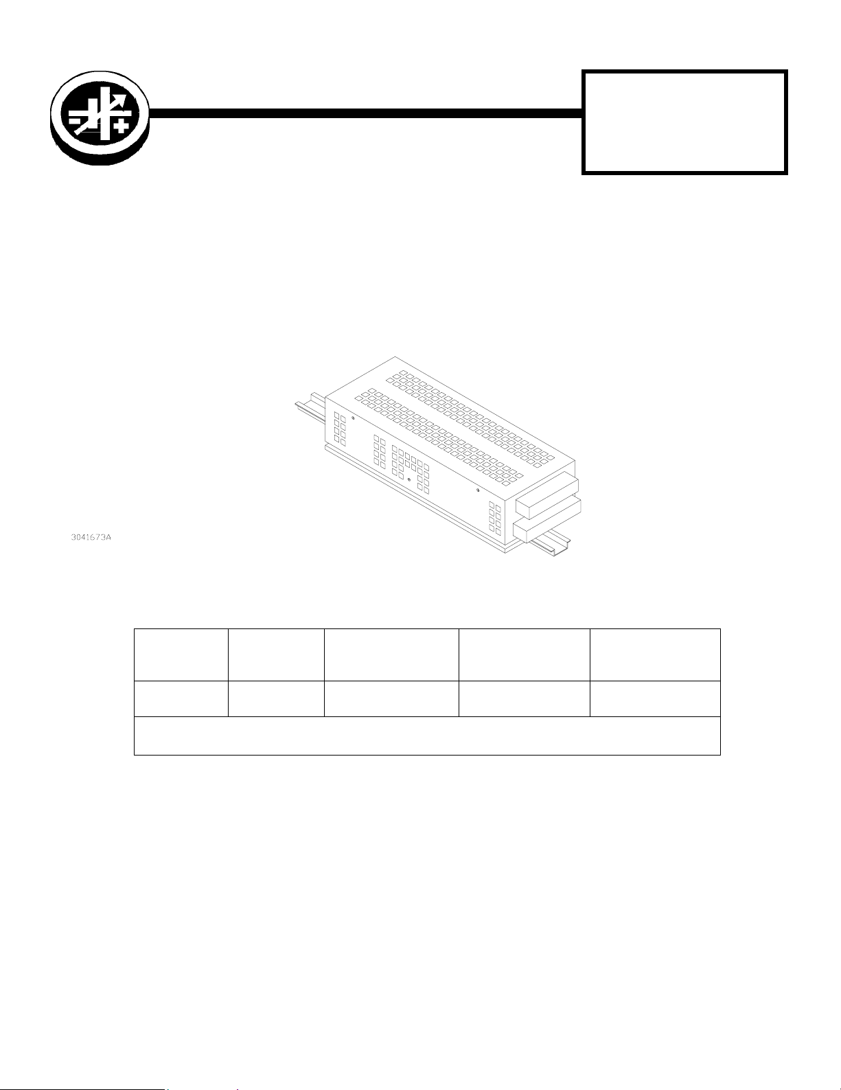
DESCRIPTION. Kepco KIT, Model DIN PTR-L contains two double mounting clip assemblies, and associated hard-
ware (see Table 1) used to install PTR Series power supplies on a DIN rail. The “L” suffix is for mounting along the long
dimension (length) as shown in Figure 1.
FIGURE 1. L SUFFIX ORIENTATION
TABLE 1. COMPONENTS SUPPLIED
KIT
MODEL NO.
DIN PTR-L 108-0362 128-1944
NOTE: Clips and Brackets are supplied preassembled into double mounting clip assemblies. To replace a mounting
clip assembly, order both the clip and bracket and assemble per Figure 2 detail.
CLIP
(QTY 4)
PART NO.
BRACKET (QTY 2)
PART NO.
SCREW (QTY 4)
PART NO.
101-0279
(8-32 x 5/16”)
WAS HE R (QTY 4)
PART NO.
103-0032
(NO.8, SPLIT, LOCK)
KEPCO, INC. " 131-38 SANFORD AVENUE " FLUSHING, NY. 11352 U.S.A. " TEL (718) 461-7000 "
http://www.kepcopower.com " email: hq@kepcopower.com
©1998, KEPCO, INC
Data subject to change without notice 228-1304
FAX (718) 767-1102
1
Page 2
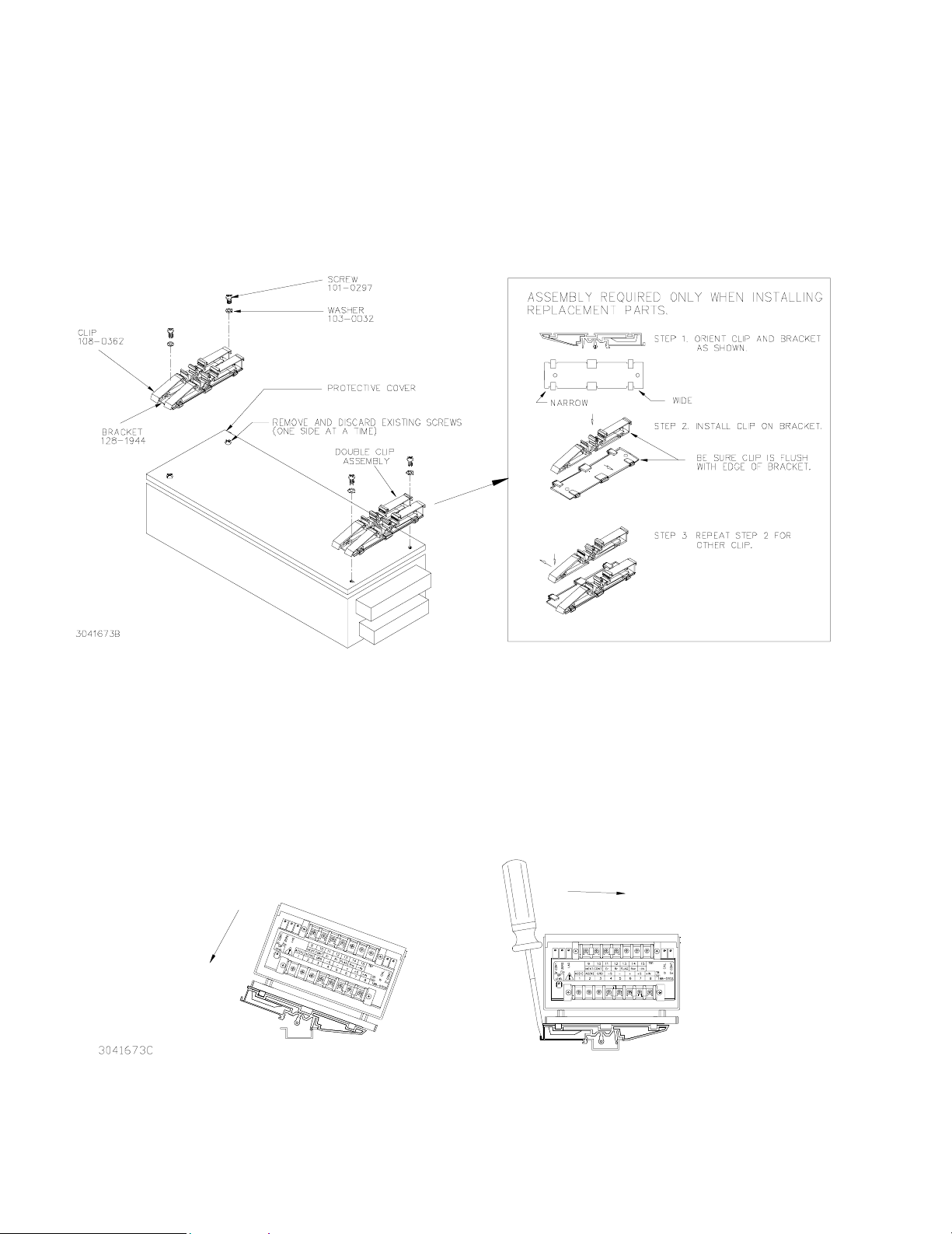
INSTALLATION
1. INSTALL CLIPS (See Figure 2).
a. Remove two screws securing one side of the protective cover (see Figure 2). Discard screws
b. Install double clip assembly on protective cover as shown in Figure 2 using two screws and washers
provided. If desired, angular side of clip assembly can face in opposite direction from that shown, but
both clip asseblies must face in the same direction.
c. Remove two screws from other side of protective cover and discard screws.
d. Install the other double clip assembly on protective cover using two screws and washers provided.
FIGURE 2. .INSTALLING CLIPS ON PROTECTIVE COVER
2. INSTALL POWER SUPPLY ON DIN RAIL. To mount the power supply on the rail insert one end of both
double clip assemblies under one edge of the rail, then snap the other end of the two clips into place
(see Figure 3A).
REMOVING POWER SUPPLY FROM DIN RAIL. While grasping the power supply with one hand, Insert a screwdriver into area shown in Figure 3B and apply leverage to disengage each double-clip from the rail. Where
mounting clips are close together, it may be necessary to apply leverage with two screwdrivers simultaneously.
An alternative is hook a tool into the square edge of the double-clip and pull to disengage the clips.
INSTALLATION
A
FIGURE 3. INSTALLATION AND REMOVAL OF POWER SUPPLY FROM DIN RAIL
B
REMOVAL
KEPCO, INC. " 131-38 SANFORD AVENUE " FLUSHING, NY. 11352 U.S.A. " TEL (718) 461-7000 "
2
http://www.kepcopower.com " email: hq@kepcopower.com
228-1304 061901
FAX (718) 767-1102
 Loading...